Page is loading ...

Gloves must be worn
at all times to reduce
risk of injury!
Owner’s Manual
& Assembly Guide
723830218
VD102
Nominal Size
10’ x 2’
www.arrowsheds.com
BUILDING DIMENSIONS
* See Inside for Detailed Safety Information.
Customer Service:
1-800-851-1085 or
Size rounded off to the nearest foot
Exterior Dimensions
(Roof Edge to Roof Edge)
Width Depth Height
Interior Dimensions
(Wall to Wall)
Width Depth Height
Door
Opening
Width Height
Approx.
Size
Storage
Area
10’ x 2’ 21 Sq. Ft. 133 Cu. Ft. 123 1/4” 30 3/4” 82 1/8” 118 1/4” 25 1/2” 80 7/8” 55 1/2” 69 1/4”
3,0 m x 0,6 m 2,0 m2 3,8 m3313,3 cm 78,1 cm 208,6 cm 300,4 cm 64,8 cm 205,4 cm 141,0 cm 175,9 cm
For proper base construction see page 12
Base
Size
121” x 28 1/4”
307,3 cm x 71,8 cm
†
†
01DS
Model No. CED102

GB: Assembly manual in additional languages available online.
Scan QR code below to access.
FR: Manuel de montage disponible en ligne dans d’autres langues.
Pour y accéder, scannez le code QR ci-dessous.
SP: Manual de montaje en idiomas adicionales disponible online.
Escanee el código QR a continuación para acceder.
DE: Montageanleitung in zusätzlichen Sprachen online verfügbar.
Scannen Sie den QR-Code unten, um darauf zuzugreifen.
I T: Manuale dell’assemblea in altre lingue disponibile online.
Per accedere effettua la scansione del codice QR in basso.
P T: Manual de montagem disponível em outros idiomas online.
Digitalize o código QR abaixo para obter acesso.
D T: Samlingshåndbog i yderligere sprog til rådighed online.
Scan QR kode nedenunder for at få adgang.
SK:Nainternetejekdispozíciinávodnazostavenievďalšíchjazykoch.
Dostanete sa k nemu naskenovaním kódu QR.
CZ:Návodkmontáživdalšíchjazycíchjekdispozicivonlineverzi.
PřístupzískáteponaskenováníQRkóduníže.
HU: Azösszeszerelésiútmutatótovábbinyelvekeniselérhetőonline.
A hozzáféréshez olvassa be az alábbi QR-kódot.
GR: Υπάρχειδιαθέσιμοστοδιαδίκτυοτοεγχειρίδιοσυναρμολόγησης
σεπερισσότερεςγλώσσες.Σαρώστετονπαρακάτωκώδικα
QRγιανααποκτήσετεπρόσβαση.
P/N 6PP722621216

2
SAFETY PRECAUTIONS...
Safety precautions MUST be followed at all times throughout the construction of your building!
Care must be taken when handling various pieces
of your building since many contain sharp edges.
Please wear work gloves, eye protection and
long sleeves when assembling or performing any
maintenance on your building.
Practice caution with the tools being used in the
assembly of this building. Be especially familiar with
the operation of all power tools.
Keep children and pets away from the worksite
during construction and until the building is
completely assembled. This will help avoid
distractions and any accidents which may occur.
NEVER concentrate your weight on the roof of the
building. When using a step ladder make sure that
it is fully open and on even ground before climbing
on it.
Do NOT attempt to assemble your building on a
windy day. The large panels can catch the wind like
a “sail”, causing them to be whipped around making
construction diffi cult and unsafe.
Do NOT attempt to assemble your building before
double checking that you have all the parts indicated
in the parts lists (page 8) as well as all hardware
(page 7). Any building left partially assembled may
be seriously damaged by even light winds.
IMPORTANT NOTE ON ANCHORING
• Your building MUST be anchored to prevent wind
damage. An anchoring kit is not supplied with your
building and you have many options when it comes to
anchoring. See anchoring page for more info.
• You must also have a temporary anchoring system in
place in case you need to take a break from assembly.
See page 4 for more info.
02A

3
ASSEMBLY TIPS & TOOLS
How to Select and Prepare Your Building Site: Before you start to assemble your
building, you will want to decide on a good location. The best location is a level area with good drainage.
• Allow enough working space so it is not diffi cult to move parts into position for assembly. Be sure there will be enough
space at the entrance for the doors to completely open. Also, there needs to be enough space outside the building to be
able to fasten the panel screws from the outside.
• Before assembling any parts, your base should be constructed and an anchoring system should be ready to use.
Watch the Weather Closely: Be sure the day you choose to install your building is dry and calm.
Do NOT attempt to assemble your building on a windy day. Be careful on wet or muddy ground.
Use Teamwork: Two or more people are required to assemble your building. One person can hold
the parts or panels in place while the other person fastens them together and handles the tools. This
makes the process of assembling your building faster and safer.
Tools and Materials: Here is a list of some basic tools and materials you will need to assemble
your building. Decide which method of anchoring and the type of base you will use to make a complete
list of the materials you will need.
• Work Gloves
• Safety Glasses
• Step Ladder
• No. 2 Phillips Screwdriver (Magnetic Tip Preferred)
• Utility Knife or Scissors
• Pliers
• Carpenter’s Level
• Tape Measure
• Power Drill (Cordless, Variable Speed)
• Nut Driver or Wrench
• Square
• String (for squaring the frame)
• Awl (to align holes)
• Lumber and/or Concrete
• Hammer and Nails
• Spade or Shovel
• Hand Saw or Power Saw
WHAT YOU NEED
RECOMMENDED TIME SAVERS
BASE PREPARATION TOOLS
03A

4
FREQUENTLY ASKED QUESTIONS
Q. How long will it take to assemble the building?
A. Assembly time depends on a variety of factors, including roof design, tools available, DIY skill and the pace
at which you work. Guidelines for each shed assembly are approximate AFTER completion of the base, and
assume two or more people working on the assembly. Generally, you should plan on at least one day working with
someone who can assist you; again, after constructing the base. Refer to the clock icons on each product page
on the website for specifi c time estimates.
Q . How do I decide where to put my shed?
A. The key to a successful assembly is to make sure the shed will be square and level when built. The shed can
be assembled directly onto level ground (grass or dirt). If you have location options, choose one that is already
fl at, with good drainage to control moisture. If you don’t have a fl at, well-drained area, you need to prepare the
space. Level the area using cinder blocks, concrete, crushed gravel or other sturdy materials. Once level with good
drainage, construct your base. Using a carpenter’s level, make sure your base is level and free of bumps or ridges
to provide good support for your building.
Q. What if I can’t fi nish my building in one session?
A. If weather conditions change so that it becomes windy or rainy, it is recommended that you stop assembly
until conditions improve. This is for your safety and for protection of the shed panels. However, do not leave
your unfi nished construction without fi rst temporarily anchoring the corners of the shed to your base and placing
weights, such as patio blocks or sandbags, on the fl oor frame. Failure to anchor the building if you leave it while
partially assembled could result in irreparable damage or personal injury if the building collapses.
Note: Most instruction manuals provide a warning note at the beginning of the installation step for corner panels,
stating that the remainder of the building assembly requires multiple hours and more than one person. Do not
continue beyond this point if you do not have enough time or help to complete the assembly that day. A partially
assembled building can be severely damaged by even light winds.
Q. Do I need to anchor my building?
A. Yes! Fully assembled buildings should be anchored using a permanent anchoring system. If you need to leave
your building before it is completely assembled, you will need to temporarily anchor the corners of the shed to your
base, and place weights, such as patio blocks or sandbags, on top of the fl oor frame.
Note: If you have to stop assembly for any reason before it is complete, do not leave your unfi nished construction
without fi rst temporarily anchoring the corners of the shed to your base and placing weights, such as patio blocks
or sandbags, on the fl oor frame.
Q. How do I temporarily anchor my building before it’s fully assembled?
A. An incomplete building must be anchored before breaking for any period of time to prevent possible damage.
•If the building is on a wood base, secure the frame with wood screws in the corners
•If the building is on a concrete base, temporarily anchor the frame in the corners
•Use patio blocks or sandbags on top of the fl oor frame as weights
•Secure the fl oor frame to the ground with ground augers or rope the frame in the corners to the ground
04A

5
Q. What kind of base do I use?
A. You can:
•Use an Arrow Base Kit
•Pour a concrete slab
•Build a wood deck/fl oor (use exterior-grade plywood)
•Use patio blocks
•Build on crushed gravel, dirt or grass
Arrow provides a base kit accessory that is an option for most building sizes. If you are building a wood deck/fl oor,
an Arrow fl oor frame kit on top of your deck/fl oor assembles in minutes and provides a fl oor frame suitable for a
5/8” exterior-grade plywood fl oor (not included). A continuous unbroken plastic vapor barrier with a thickness of 6
mil. between the ground and the building’s base is also recommended.
Q. How should I measure for my base?
A. Shed dimensions are provided in “nominal” size. Nominal sizes are roof-edge measurements rounded to the
nearest foot and are not the measurements to use for constructing the shed base. So, carefully check the exact,
recommended base size in the specifi cations for your shed model.
Q. How do I align the holes in the wall panels with the holes in the fl oor frame?
A. Make sure that the shed is level and square, with the correct fl oor frame size, and that the corner panels are
installed correctly. Line up the large hole in the panel with the small holes in the fl oor frame. An awl can be used to
help align the holes.
Q. How do I align the holes in the roof panels with the holes in the roof beam and side wall angles?
A. Your building must be level and square in order for the holes to align. It must be square at both the top and
bottom. Check that the building is square by measuring diagonally. The two diagonal measurements will be equal.
If your building is out of square, carefully rock and push the shed until it is square. Also, try loosening the roof
beams to give more play and fl exibility. Non-alignment can also occur if your building is not level. You can raise
corners and shim under them to make it level. Check that the panels are installed in the proper location. The
building should not be permanently anchored until the complete unit is assembled; otherwise, you will not be able
to make adjustments for squareness during assembly. Do not attach the bottom of the roof panels to the side wall
angles until all the roof panels are up.
Note: If you have to stop assembly for any reason before it is complete, do not leave your unfi nished construction
without fi rst temporarily anchoring the corners of the shed to your base and placing weights, such as patio blocks
or sandbags, on the fl oor frame.
Q. How do I ensure that the sliding doors on the building will hang level?
A. Make sure that the door track has been correctly installed, with the long leg on top and the short leg on the
bottom. Check that the door slides are straddling the upper and lower legs of the door track assembly, putting the
door slide only halfway in the track. Also, the rounded end of the door slide should be at the bottom and the square
end at the top.
Q. What kind of customer support is available?
A. Our instruction manuals contain step-by-step assembly illustrations and guide you from preparation through
assembly to care and maintenance of your fi nished building. Each part is marked with a factory number for easy
identifi cation. In addition, our assembly animation (located under the Customer Support menu on the website)
provides helpful tips. But if you need to reach someone at Arrow, you can contact Arrow Customer Service, toll free,
at 1-800-851-1085 (press 1) or via e-mail at [email protected]. Have your model number and instruction
manual with you when you call.
05A

6
Q. What if the rear wall angle and channels are too large to fi t inside of the rear wall panels?
A. Check the dimensions of wall assemblies. They should be slightly smaller than the fl oor frames. Lay the
assemblies on top of the rear fl oor frame and pull them up to the top of the wall panels causing the corner panels
to stand erect and not lean inward. Caution: Be careful to not scratch the panels on the way up.
Q. The wide rib always overlaps the crimped rib. Is there ever an exception?
A. This sequence is to be followed through the assembly process. However, this will typically happen once on the
rear and once on each side wall (vertical wall units only) where there will be either two crimped ribs overlapping or
two wide ribs overlapping. This may give it a tighter fi t, but it will work.
Q. Can the building be painted?
A. The buildings can be painted with an exterior-grade paint designed for use on steel. Contact your local paint
supplier for recommendations.
Q. I heard that rust might be an issue with steel; is it?
A. While steel can rust, with proper care this should not be an issue. For a long-lasting fi nish, periodically clean
the exterior surface and apply spray-on car wax. Touch up scratches as soon as you notice them by immediately
cleaning the area with a wire brush or emery paper, washing it and applying touch-up paint. This will minimize rust
and maintain your shed’s attractive appearance for years.
Q. How do I take care of dents in my shed?
A. Proper selection of shed size, including a suffi cient door-opening width, and proper placement of your shed
should minimize the possibility of damage. If a dent does occur, carefully push the dent out from the opposite side.
If the paint has been scratched or removed, touch up the area as soon as you notice it. Immediately clean the area
with a wire brush or emery paper, wash it and apply touch-up paint. This will minimize rust and maintain your shed’s
attractive appearance for years.
Still have questions? Visit us online at www.arrowsheds.com to view lots of helpful tips and information
regarding all of our available products. You can also contact our Customer Service team at 1-800-851-1085
(press 1), or via e-mail at [email protected].
06A
At the top of each page you will see one or more Part
Cues like the one to the left. These Part Cues are
designed to help you quickly identify the parts needed
for each step.
##### 5
Part No. Quantity Needed
End View
Part Name Part Name
Confi rm that all hardware and parts are
present before attempting to assemble
your building.
Customer Service:
1-800-851-1085 or
For missing or damaged parts contact
Customer Service. Do not return to store.
Part Numbers
Part Number
1. Each part has an identifying part number on it.
2. Part Numbers are referenced in each step.
3. Unpainted parts have a stamped in number and painted
parts have a number that is inked on.
Remove inked on numbers with soap and water after assembly.

7
HARDWARE LIST...
07DG
The fasteners used in each step are shown
actual size at the top of each page. If you
are unsure which fastener to use, hold it up
to the picture and use the one that matches.
11
13
1
Hardware Views by Key No.
2 3
4 6
87 9
10 12
14
5
BS
SS
SB
HN
Hex. Nut
Black Screw
Small Bolt
Small Screw
- HN
- BS
- SB
- SS
Various fasteners are used throughout the construction
of your storage unit. In each step you will see the
abbreviations listed below used in the illustrations to help
you identify which fastener to use.
Key Part Part Qty.
No. No. Description List
1 65103 Hex Nut (#8-32 x 11/32) 77
2 65900A Black Screw (#10B x 1/2) (13mm) 8
3 65923 Small Bolt (#8-32 x 3/8) (10mm) 77
4 65004 Small Screw (#8AB x 5/16) (8mm) 196
5 66646 Washer Sheet 3
6 66045 Door Handle 2
7 66769 Door Slide 4
8 66382 Lower Door Guide 4
9 6228 Track Support 2
10 5971 Roof Beam Bracket 4
11 67468 Peak Cap 2
12 66183L Left Roof Trim Cap 2
13 66183R Right Roof Trim Cap 2
14 67293 Weather Stripping 1

6
PARTS LIST...
8
Key Part Part Qty.
No. No. Description List Selected End Views by Key No.
987
2013,27 19
2522 23
10 11 12
654
321
08DG
1 9367 Front Floor Frame 2
2 8934 Ramp 1
3 8984 Side Floor Frame 2
4 8936 Rear Floor Frame 2
5 5288 Corner Post 4
6 5287 Splice Post 1
7 9366 Door Track 2
8 6403 Door Track Splice 1
9 6637 Side Wall Angle 2
10 9338 Right Rear Wall Angle 1
11 9339 Left Rear Wall Angle 1
12 7311 Door Jamb 2
13 9344 Siding Stud 2
14 8737 Front Siding 6
15 8827 Side Siding 6
16 8736 Rear Siding 6
17 6000 Right Gable 2
18 6001 Left Gable 2
19 6635 Gable Brace 2
20 6659 Roof Beam 4
21 6543 Roof Panel 2
22 6014 Side Roof Trim 2
23 6868 Ridge Cap 1
24 10472 Door 2
25 10497 Horizontal Door Brace 4
26 3719 Door Handle Brace 2
27 6301 Vertical Door Brace 2
28 9365 Front Wall Channel 2
29 69835 Edge Trim (Green) 4
26 28

ASSEMBLY BY KEY NO.
9
09DG
1
2
5
4
5
4
3
3
9
9
1
13 11
10
7
7
6
5
12
8
12
13
514
14
14
14
14
14
15
15
15
15
15
15
16
16
16
16
16
16
17
17
18
18
19
19
20
20
20
21
21
22
22
23
24
24
25
25
25
25
27
27
29
29
29
29
20
28
28
26
26

ASSEMBLY OVERVIEW
Build the Floor Frame. Install Corner Post, Door Track, Side
Wall Angles, and Rear Wall Angle.
Install Splice Post and Door Jambs. Install Siding Studs.
Install Rear Siding Panels. Install Side Siding Panels.
10AE
10

ASSEMBLY OVERVIEW
Install Front Siding Panels. Install Right and Left Gables.
Install Roof Beams. Install Roof Panels.
Install Ridge Cap, Side Trim, and
Corner Cap.
Install Doors
11AE
Shed is now complete.
11

12
No matter which of the options below you choose for a base, an ARROW ANCHORING KIT is
recommended as an effective method of properly securing your building after assembly is complete.
OPTION 1: Directly on ground (earth)
Assemble your building directly on level ground (grass, dirt, rock, sand, etc.).
OPTION 2: Wood Platform
If you decide to build your own base, be sure to select the appropriate materials.
These are the recommended materials for your base:
• 2 x 4's (38 mm x 89 mm) Pressure Treated Lumber • 5/8" (15,5 mm) 4 x 8 (1220 mm x 2440 mm) Plywood-exterior grade
• 10 & 4 penny Galvanized Nails • Concrete Blocks (optional)
NOTE: Pressure Treated Lumber must not be used where it will make contact with your storage building. The properties of
Pressure Treated Lumber will cause accelerated corrosion.
The platform should be level and fl at (free of bumps, ridges etc.)
to provide good support for the building. The necessary materials
may be obtained from your local lumber yard.
To construct the base follow instructions and diagram.
Construct frame (using 10 penny galvanized nails)
Measure 16"/24" (40,6 cm/61,0 cm) sections to construct
inside frame (see diagram)
Secure plywood to frame (using 4 penny galvanized nails)
OPTION 3: Concrete Slab
The slab should be at least 4" (10,2 cm) thick. It must be level
and fl at to provide good support for the frame.
The following are the recommended materials for your base.
• 1 x 4's (19 mm x 89 mm) (will be removed once the concrete cures)
• Concrete • Sheet of 6 mil plastic
• We recommend for a proper strength concrete to use a mix of:
1 part cement • 3 parts pea sized gravel • 2 1/2 parts clean sand
Prepare the Site/Construct a Base
1. Dig a square, 6" (15,2 cm) deep into the ground (remove grass).
2. Fill up to 4" (10,2 cm) in the square with gravel and tamp fi rm.
3. Cover gravel with a sheet of 6 mil plastic.
4. Construct a wood frame using four planks of 1x4 (19 mm x 89 mm)
lumber.
5. Pour in concrete to fi ll in the hole and the frame giving a
total of 4" (10,2 cm) thick concrete. Be sure surface is level.
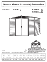
CONSTRUCTING A BASE...
FRONT
(DOOR)
FRONT
(DOOR)
Note: Finished Slab dimensions, with lumber removed.
Note: Platform/Slab will extend 9/16" (1,4 cm) beyond
fl oor frame on all four sides. Seal this 9/16" (1,4 cm)
of wood with a roofi ng cement (not included), or bevel
this 9/16" (1,4 cm) of concrete when pouring, for good
water drainage.
121"
307,3 cm
16"/24"
40,6 cm/61,0 cm
28 1/4"
71,8 cm
28 1/4"
71,8 cm
12DG
12
121"
307,3 cm

13
You will need for this page: Washers are to be used on
painted parts only. Washers
are not necessary on unpainted
parts and there are not enough
to use on every screw and bolt.
Step 1: Floor Frames
13DG
CHECK THAT ALL ASSEMBLED PARTS ARE
THE CORRECT LENGTH BEFORE CONTINUING
Finished Length
119 3/8” (303,2 cm)
FRONT
9367
8934
9367
Four (4) Screws per side.
Overlap the Ramp and two (2) Front Floor Frames
so that four (4) holes align at each end as shown.
Insert four (4) Small Screws in each end.
1
2
Confi rm that the drain holes are facing outside
the building. Check that the fi nished length of the
Assembly is 119 3/8” (303,2 cm). Set aside for use
in Step 4.
FRONT
Drain holes must face outside the building.
8934
Ramp
1
9367
Front Floor
Frame
2
(QTY: 8)
SS

14
8936
8936
Assemble the Rear Floor Frames.
Finished Length
119 3/8” 303,2 cm
(QTY: 5)
8936
Rear Floor
Frame
2
Bolts thru Bottom.
Bolts thru Top.
You will need for this page:
Step 1: Floor Frames
Overlap two (2) Rear Floor Frames as shown
and secure with fi ve (5) bolts. Two (2) bolts
must enter from bottom.
3
4
Check that the fi nished length of the Assembly
is 119 3/8” (303,2 cm). Set aside for use in
Step 4.
14DG
CHECK THAT ALL ASSEMBLED PARTS ARE
THE CORRECT LENGTH BEFORE CONTINUING

CHECK THAT ALL ASSEMBLED PARTS ARE
THE CORRECT LENGTH BEFORE CONTINUING
You will need for this page:
Step 2: Wall Frame
Overlap the Right and Left Rear Wall Angles as
shown and secure using one (1) Small Bolt and
Nut through the center hole.
1
2
Check that the fi nished length of the Assembly is
118 1/8” (300,0 cm). Set aside for use in Step 6.
9339
Left Rear
Wall Angle
1
9338
Right Rear
Wall Angle
1
15DG
15
9338
9339
Finished Length
118 1/8” 300,0 cm
(QTY: 1)
SB

You will need for this page:
Finished Length
118 1/8” 300,0 cm
CHECK THAT ALL ASSEMBLED
PARTS ARE THE CORRECT
LENGTH BEFORE CONTINUING
Slide all four (4) Door Slides into Track.
Insert screws into bottom side only. The
Gables will fasten to the Door Track
using the holes on the top side.
Track Splice
1
6403
Door Track
2
9366
6403
9366
9366
To remove or install Door Slides:
• Remove Doors from Slides and set aside.
• Using pliers, bend down a corner of the Door Track.
• Remove or install Door Slides.
• Carefully bend the corner back into position.
Slides should be installed in Door Track prior to installation. However, if this step is overlooked
or if the Slides need to be removed for maintenance, the following procedure may be used.
Step 3: Door Track
2
Position four (4) Door Slides in the Door Track.
Check that the fi nished length is 118 1/8” (300,0 cm).
Set aside for use in Step 5.
Align two (2) Door Tracks with the four (4) holes in
the bottom of the Door Track Splice and insert four
(4) Small Screws.
1
The bottom side of the Door Tracks and
the Door Track Splice has only four (4)
holes. The top side has many holes.
Fasten bottom side only.
(QTY: 4)
16DG
16
SS
Door Slide
4
66769
CORRECT INCORRECT
Long Leg on top.
Door Slide
END VIEW

Assemblies from Step 1:
• Front Floor Assembly (1)
• Rear Floor Assembly (1)
(QTY: 2)
Do NOT fasten your Floor Frames to your Base at this time.
You will anchor your building after it is erected. If using a
Floor Frame Kit, you must wait until after assembly to install it.
The Floor Frame must be BOTH square AND
level or the holes will not line up properly.
Insert a bolt and nut thru bottom of
Front Floor Frame at each front corner
to secure Front Frame to Side Frames.
Front Corner
Back Corner
You will need for this page:
Step 4: Frame Assembly
Assemble Floor Frame with two (2) Small Screws at each
corner as shown. At the front corners insert one (1) Small
Bolt and Nut through the bottom of the Frame as shown.
1
Do not continue beyond this point unless you have enough time to complete the
shed today. The remainder of assembly may take several hours and requires at
least two people. A partially assembled shed left overnight can be seriously damaged by
even light winds. It is recommended that you wait and complete the remainder of shed
assembly on a day which you have plenty of time to fi nish the shed safely and completely.
When diagonal measurements
are equal, the Frame is square.
(QTY: 8)
17DG
17
FRONT
Side Floor
Frame
2
8984
SS SB
8984
8984
Rear Floor Assembly
Front Floor Assembly
Overlap Floor Frames as shown. Set Floor
Frame with large holes on top at each corner.

6
18
18DS
You will need for this page:
4
4
3
2
1
5288
Corner Post
4 6637
Side Wall
Angle
2
(QTY: 18)
Assemblies from step 2:
• Rear Wall Angle Assembly (1)
Assemblies from step 3:
• Door Track Assembly (1)
The Floor Frame must be square
and level or holes will not align.
Support the Corner Posts with
stakes or other devices until Door
Jambs and Splice Post are attached.
Wall Angles must face
inside building.
Long leg of Rear Wall
Assembly faces down.
Step 5: Posts/Top Frames
5288 5288
52885288
SIDE SIDE
REAR
FRONT
TOP VIEW
6637
6637
Front
Rear Wall Angle Assembly
Door Track Assembly
Short Leg on Bottom.
Opening Faces In.
Long Leg on Top.
SS
Position Corner Posts at the corner of
the Floor Frame as shown. Fasten the
Corner Post to the Floor Frame using
two (2) Small Screws in each Post.
1
Attach Door Track Assembly to the
inside of front Corner Post using one
(1) Small Screw in each Post.
2
Attach Rear Wall Angle Assembly to
the inside of rear Corner Post using
two (2) Small Screws in each Post.
3
Attach Side Wall Angles to the inside
of side Corner Post using one (1)
Small Screw in each Post.
4

You will need for this page:
Splice Post
1
5287
Siding Stud
2
9344
Step 6: Splice Post/Door Jamb/ Studs
(QTY: 8)
19DG
19
Position Splice Post at the center of the rear
wall and fasten to Rear Wall Angle using four
(4) Small Bolts and Nuts and two (2) Small
Screws to the Floor Frame.
1
Following dimensions, measuring from end of
Rear Wall Angle, place Stud between each
Corner and Splice Post at the rear of building.
Position Stud inside top angle and fasten with
one (1) Small Screw at the lower hole.
2
Place bottom of Stud Assembly over Floor
Frame as shown. Do not fasten bottom at
this time. Repeat procedure for the remaining
Stud Assemblies around the building.
3
Fasten Door Jambs using four (4) Small
Screws, two (2) Small Screws in the Door
Track and two (2) Small Screws in the Floor
Frame. Must be a 7/8” (2,2 cm) gap between
the end of the Ramp and edge of Door Jamb.
Notched edge must face towards the center of
the building.
4
7311
Door Jamb
2
(QTY: 4) (QTY: 4)
FRONT
29 3/16”
(74,1 cm)
29 3/16”
(74,1 cm)
9344
9344
5287
SS
SS SB
SB
SS
SS
1
2
NOTCHED EDGE MUST FACE
CENTER OF BUILDING
FRONT
7311
7311
7/8” (2,2 cm) Gap
SS
SS
SS
SS
4
3
/