Paslode T200-F18 Operating instructions
- Category
- Power tools
- Type
- Operating instructions

MODEL T200-F18
MODEL T125-F18
Finish Nailers
IMPORTANT!
DO NOT DESTROY
It is the customer’s responsibility to have all
operators and service personnel read and
understand this manual.
OPERATING MANUAL AND
SCHEMATIC
P

INTRODUCTION
The PASLODE
®
T200-F18 and T125-F18 finish nailers are quality-built tools designed for use in
residential trim applications. These tools will deliver efficient, dependable performance when used
according to the manufactures guidelines. Please study this manual including the safety
instructions to fully understand the operation of these tools.
TOOL AND FASTENER SPECIFICATIONS ................................................... 3
SAFETY INSTRUCTIONS .............................................................................. 4
INSTRUCTIONS FOR LOADING ................................................................... 5
EXPLODED VIEW AND SPARE PARTS LIST ............................................... 6
ACCESSORIES .............................................................................................. 8
TOOL WARRANTY AND LIMITATIONS
2

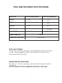
MODEL NO. T200-F18 (Part# 500959) T125-F18 (Part#501161)
HEIGHT 9-3/4"
WIDTH 2-3/8"
LENGTH 9-3/4"
WEIGHT 2.1lbs.
NAIL LENGTH 5/8" - 2" 5/8” - 1-1/4”
SHANK DIAMETER 18 gauge
OPERATING PRESSURE 70 to 100 p.s.i.
TOOL AIR FITTINGS:
This tool uses a 1/4” N.P.T. male plug. The inside diameter should be .28” (7mm)
or larger. The fitting must be capable of discharging tool air pressure when
disconnected from the air supply.
OPERATING AIR PRESSURE:
70 to100 p.s.i. Select the operating air pressure within this range for best tool
performance.
DO NOT EXCEED THIS RECOMMENDED OPERATING PRESSURE.
TOOL AND FASTENER SPECIFICATIONS
3
7-1/2”
2-3/8”
9-2/3”
1.75 lbs.

DANGER
Failure to follow any of the above instructions could result in severe personal
injury to tool user and bystanders or cause damage to tool and property.
Contact your local Paslode Representative for presentation of Paslode’s Safety Awareness Program
SAFETY INSTRUCTIONS
SAFETY FIRST
These safety instructions provide information
necessary for safe operation of Paslode
®
tools. DO
NOT ATTEMPT TO OPERATE THE TOOL UNTIL
YOU READ AND UNDERSTAND ALL SAFETY
PRECAUTIONS AND MANUAL INSTRUCTIONS.
WEAR EYE AND HEARING PROTECTION
Always wear hearing and eye protection devices,
including side shields, when operating or working in
the vicinity of a tool.
THE TOOL MUST BE USED ONLY FOR THE
PURPOSE FOR WHICH IT WAS DESIGNED
Do not throw the tool on the floor, strike the housing
in any way or use the tool as a hammer to knock
material into place.
NEVER ENGAGE IN HORSEPLAY WITH THE
TOOL
The tool is not a toy so do not use it like one. Never
engage in horseplay with the tool or point it at
yourself or any other person, even if you think it is
not loaded.
NEVER ASSUME THE TOOL IS EMPTY
Check the magazine for fasteners that may be left in
the tool. Even if you think the tool is empty or
disconnected, never point it at anyone or yourself.
Unseen fasteners could fire from the tool.
NEVER CLAMP THE TRIGGER IN A LOCKED OR
OPERATING POSITION
The trigger of the tool must never be tampered with,
disabled or clamped in a locked or operating position
since this will cause the tool to drive a fastener any
time the work contacting element depressed.
DO NOT LOAD FASTENERS WITH THE AIR LINE
CONNECTED, OR WITH THE TOOL TRIGGER OR
WORK CONTACTING ELEMENT DEPRESSED
When loading fasteners into the tool be sure you
disconnect the air line and that you do not depress
the trigger or work contacting element.
OPERATE THE TOOL ONLY ON A WORKPIECE
The tool should be operated only when it is in
contact with the workpiece. Even then you should
be careful when fastening thin material or working
near the edges and corners of the workpiece since
the fasteners may drive through or away from the
workpiece.
DO NOT DISABLE OR REMOVE THE WORK
CONTACTING ELEMENT
This tool is equipped with a safety mechanism,
called a work contacting element, to help prevent
accidental firing. Never tamper with, disable or
remove the work contacting element. Do not use the
tool unless the work contacting element is working
properly. The tool could fire unexpectedly.
DISCONNECT THE TOOL WHEN NOT IN USE
Always disconnect the tool from the air line when it is
not in use or when you leave the work area. The tool
should never be left unattended because people who
are not familiar with the tool might handle it and
injure themselves or others.
CARRY THE TOOL ONLY BY THE HANDLE
Always carry the tool by the handle only. Never carry
the tool by the air hose or with the trigger depressed
since you could drive a fastener unintentionally and
injure yourself or someone else.
DO NOT WEAKEN THE TOOL HOUSING
The tool housing is a pressure vessel and should never
be weakened by having your company’s name, area of
work or anything else stamped or engraved into its
surface.
DISCONNECT THE TOOL WHEN PERFORMING
REPAIRS AND CLEARING JAMS
Never attempt to clear a jam or repair a tool unless you
have disconnected the tool from the air line and
removed all remaining fasteners from the tool.
ALWAYS USE THE PROPER FITTING FOR THE
TOOL
Only MALE pneumatic type air connectors should be
fitted to the tool, so that high pressure air in the tool is
vented to atmosphere as soon as the air line is
disconnected.
NEVER install FEMALE quick disconnect couplings on
the tool. Female couplings will trap high pressure air in
the tool when the air line is disconnected, leaving the
tool charged and able to drive at least one fastener.
DO NOT EXCEED THE MAXIMUM RECOMMENDED
AIR PRESSURE
Operate the tool only at the recommended air pres-
sure. Do not exceed the maximum air pressure marked
on the tool. Be sure the air pressure gauge is
operating properly and check it at least twice a day.
Never use any bottled air or gases such as oxygen to
operate the tool since they could cause the tool
to
explode.
KEEP THE TOOL CLEAN AND LUBRICATED
Clean the tool at least daily and lubricate as required.
Never operate a dirty or malfunctioning tool.
USE ONLY PASLODE RECOMMENDED PARTS AND
FASTENERS
Use only parts and fasteners specifically designed and
recommended by Paslode for use in the tool and for
work to be done. Using unauthorized parts and
fasteners or modifying the tool in any way creates
dangerous situations. Replace all missing warning
labels---refer to tool schematic for correct placement
and part number.
4

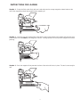
Step No. 1 – Grasp the finish nailer firmly with one hand and press the orange magazine release button at the
rear of the magazine and pull the magazine back towards you.
Step No. 2 – Insert the strip of 18 gauge finish nails with the point of the fastener facing down and place the point
of the fastener into the bottom of the magazine channel. Placing fasteners on the top of the magazine will cause
jamming.
Step No. 3 – Push the magazine firmly towards the front of the tool until it locks in place. The tool is now ready for
use.
INSTRUCTIONS FOR LOADING
5

1 500976 1 Deflector
2 500977 1 Bolt w/ Flat Washer
3 500978 1 Hex Soc. Hd. Screw
4 500979 1 Cap (T200)
501170 1 Cap (T125)
5 500980 1 Seal
6 500981 1 Compression Spring
7 500982 1 O-Ring
8 500983 1 O-Ring
9 500984 1 Head Valve Piston
10 500985 1 O-Ring
11 500986 1 Gasket, Cap
12 500987 1 Piston Ring
13 500988 1 O-Ring
14 500989 1 Piston Assembly (T200)
501171 1 Piston Assembly (T125)
15 500990 1 Cylinder (T200)
501172 1 Cylinder (T125)
16 500991 1 O-Ring
17 500992 1 Cylinder Ring
18 500993 1 Bumper
19 500994 1 Driver Guide (T200)
501173 1 Driver Guide (T125)
20 500995 1 O-Ring
21 500996 1 Trigger Valve Head
22 500997 1 Spring
23 500998 1 Plunger
24 500999 1 O-Ring
25 501082 1 O-Ring
26 501083 1 Plunger Cap
27 501084 1 Roll Pin
28 501085 1 Trigger Lever
29 501086 1 Trigger
30 501087 1 Roll Pin
31 501088 1 Trigger Pivot Pin
32 501089 1 Urethane Retainer
33 501090 1 Housing Assembly
34 501091 1 Air Plug
35 501092 1 Dust Cover
36 501093 1 Bolt Assembly (T200)
501176 1 Bolt Assembly (T125)
37 501094 1 Front Cover
38 501095 1 Front Guide (T200)
501177 1 Front Guide (T125)
39 501096 1 Fixed Pin
40 501097 1 Hex Soc Hd Bolt
41 501098 1 Back Plate (T200)
501178 1 Back Plate (T125)
42 501099 1 Fixed Magazine (T200)
501179 1 Fixed Magazine (T125)
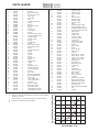
PARTS LEGEND T200-F18, 500959
T125-F18, 501161
* Denotes Normal Wear Items.
** Make sure Warning Label (500492 or 501197) is properly affixed.
Replace if necessary.
Label available at no charge through the Service Parts Dept.
▲ Apply Loctite 242 (Blue) Part No. 093500.
43 501100 1 Flat Bar (T200)
501180 1 Flat Bar (T125)
44 501101 1 Bolt Assembly
45 501102 1 Stop
46 501103 1 Bracket (T200)
501187 1 Bracket (T125)
47 501104 1 Follower (T200)
501181 1 Follower (T125)
48 501105 1 Shaft
49 501106 1 Follower Spring (T200)
501183 1 Follower Spring (T125)
50 501107 1 Moveable Magazine (T200)
501182 1 Moveable Magazine (T125)
51 501108 1 Spring Cover
52 501109 1 Latch (T200)
501184 1 Latch (T125)
53 501110 1 Latch Pin (T200)
501185 1 Latch Pin (T125)
54 501111 1 Lock Spring
55 501112 1 Latch Cover (T200)
501186 1 Latch Cover (T125)
56 501113 1 Tap Bolt
57 501191 1 W.C.E. Guide
58 501115 1 Roll Pin
59 501192 1 W.C.E. Spring
60 501193 1 Upper W.C.E.
61 501174 1 E-Ring
62 501175 1 Interm. W.C.E. (T200)
501195 1 Interm. W.C.E. (T125)
63 501120 1 Lower W.C.E. (T200)
501196 1 Lower W.C.E. (T125)
64 501121 1 Protective Tip
65 501122 1 Anchor Block
66 501123 1 Magazine Spacer
67 501124 1 Lock Spring
68 501125 1 Latch
69 501126 1 Flat Washer
70 501127 1 Hex Soc Hd Bolt
71 501128 1 Bolt Assembly
72 501188 1 W.C.E. Stop
73 501130 1 Hex Soc Hd Bolt
74 501131 1 Lock Nut
75 500492 1 Warning Label (T200)
501197 1 Warning Label (T125)
76 501134 1 Magazine Label (T200)
501198 1 Magazine Label (T125)
77 501135 2 Housing Label
78 501189 1 Hex Socket Button Hd Bolt
79 501190 1 Stop
80 501194 1 Adjuster
*
*
*
*
*
6
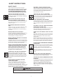
AIR CONSUMPTION - SCFM/FASTENE
R
AIR PRESSURE - PSIG
25
30
35
40
45
50
70 80 90 100
20
55
0.046
0.039
0.032
0.025
0.022
0.026
0.029
0.033
T125-F18
T200-F18

51
T200-F18
500959
T125-F18
501161
7
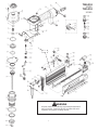
WARNING
All parts must be periodically inspected and replaced if
worn or broken. Failure to do this can affect the tool’s
operation and present a safety hazard.
55
77
76
75

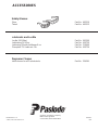
ACCESSORIES
An Illinois Tool Works Company
888 Forest Edge Drive
Vernon Hills, Illinois 60061-3105
PRINTED IN U.S.A.
© 2001, Illinois Tool Works, Inc.
405645-2
6/01
Safety Glasses
Clear Part No. 402510
Tinted Part No. 402512
Lubricants and Loctite
Loctite 242 (Blue) Part No. 093500
Lubricating Oil 16 oz. Part No. 403720
Lubricaing Oil with Anitfreeze 8 oz. Part No. 219090
Chemplex 710 Lubricant 1lb. Part No. 403734
Degreaser Cleaner
Ideal cleaner for all Paslode tools. Part No. 219086
P
-
 1
1
-
 2
2
-
 3
3
-
 4
4
-
 5
5
-
 6
6
-
 7
7
-
 8
8


Paslode T200-F18 Operating instructions
- Category
- Power tools
- Type
- Operating instructions
Ask a question and I''ll find the answer in the document
Finding information in a document is now easier with AI
Related papers
-
Paslode C-55 15 degree Coil Nailer Owner's manual
-
-
-
-
-
-
-
-
-
Other documents
-
Samsung T200 User manual
-
MasterCraft AIR-POWERED BRAD NAILERS User manual
-
 Tributaries T200 User manual
-
HP t200 Zero Client for MultiSeat Reference guide
-
RPB T200 Installation guide
-
Campbell Hausfeld CHN10202 User manual
-
Campbell Hausfeld NB006750 User manual
-
-
-
