Page is loading ...

1
SAW Learn Mode Water Sensor
ITI Part No. 60-744
Installation Instructions
Document Number: 466-1539 Rev. C
January 2000
Product Summary
The ITI SAW Learn Mode™ Water Sensor detects a water
leak in a home or business. The detector is connected to the
sensor by an 8-foot (2.4-meter) cable. Water that reaches
both detector contact points activates the sensor, causing it
to transmit an alarm signal.
The SAW 319.5 MHz transmitter has an operating range of
at least 500 feet in open air (depending on panel type and
installation environment). The sensor has an estimated bat-
tery life of 3 to 5 years.
Tools and Equipment Needed
❑Double-sided tape (included) for mounting the detector
and sensor
❑1.5-inch wire (used for programming the sensor)
❑#6 pan head screws (included) if mounting sensor with-
out double-sided tape is preferred
❑Slotted screwdriver (not included) if mounting sensor
with screws
Installation Guidelines
This section describes the detector and sensor (transmitter)
mounting requirements.
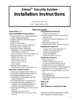
Detector Mounting:
❑Install the detector on the floor for low water-level
detection or on the bottom of a wall, just above the
floor for higher water-level detection.
Figure 1. Detector Mounting Options
Note
The contact points on the detector may corrode if
exposed to water for more than 24 hours. Instruct your
customer to temporarily remove the detector from the
water, if possible, during a flood to avoid damaging the
detector.
Sensor Mounting:
❑Program and test the sensor before mounting.
❑Install the sensor where it is easily accessible and not
exposed to moisture or extreme temperatures.
❑Locate the sensor within 100 feet of the panel when-
ever possible. Although the sensor has an open-air
range of at least 500 feet, the indoor range may be less.
Programming
This section describes how to add (learn) the sensor into the
memory of compatible panels.
Simon® Panels
1. Open the control panel cover.
2. Enter Utility Access Code 1 or 2 using the red-num-
bered buttons.
3. Press Add from the Start Menu.
4. Press the Sensor/Remote button from the Main menu
until you hear the location name you wish to use with
the sensor. The panel announces the names in the fol-
lowing order:
keychain remote, touchpad remote, front door, back
door, garage door, bedroom, guest room, child’s room,
utility room, living room, dining room, bathroom, laun-
dry room, kitchen, office, den, garage, special chime,
basement, upstairs, downstairs, hallway, medicine cab-
inet, closet, attic.
Each name may be used more than once.
Note
When adding sensors, if you wish to use a more
descriptive location you may press the option button to
use the compass directions (north, north east, east,
south east, south, south west, west, north west).
5. Press DONE.
6. Enter the sensor type number (29) with the red num-
bered keys.
Detector mounted
for high level water
(on wall)
Detector mounted
for low level water
(on floor)
Transmitter
Transmitter
6$:#/HDUQ#0RGH#
6$:#/HDUQ#0RGH#6$:#/HDUQ#0RGH#
6$:#/HDUQ#0RGH#
:DWHU#6HQVRU
:DWHU#6HQVRU:DWHU#6HQVRU
:DWHU#6HQVRU

2SAW Learn Mode Water Sensor
Testing the Water Sensor
Note
If you wish to use a sensor number other than the next
available, enter a 2-digit sensor number with the red
numbered keys immediately after entering the sensor
type.
7. Remove the sensor outer cover by pressing the cover
release button on the end of the transmitter (see Figure
2).
Figure 2. Transmitter Cover Release Button
8. Press and hold the “PRESS TO PROGRAM” plastic
tab on the sensor until the control panel confirms the
programming.
Concord™ and Concord Express™ Panels
The sensor must be in the alarm state for Concord family
panels to learn the sensor correctly.
1. Remove the sensor outer cover by pressing the cover
release button on the end of the transmitter (see Figure
2).
2. Short across the detector by wrapping the wire around
the two contact points (see Figure 3).
Figure 3. Detector Components (Shown Upside-Down)
3. Using an alphanumeric touchpad, enter program mode
by pressing 8 + 4 3 2 1 + 0 + 0. The display
shows SYSTEM PROGRAMMING.
4. Press ƒ and the display shows SECURITY.
5. Press A or B repeatedly until the display shows SEN-
SORS.
6. Press ƒ and the display shows LEARN SENSORS.
7. For panels with partitions, press ƒ and the display
shows SENSOR PTN 1.
Press ƒ to select partition 1 or press 2 + ƒ to select
partition 2.
8. The display should now show SENSOR GROUP 00.
Press 2 + 9 to select sensor group 29, then press ƒ.
9. The display shows TRIP SENSOR nn, where nn is the
next available sensor number. To change the displayed
sensor number, select the desired 2-digit sensor number
and press ƒ.
10. Press and hold the “PRESS TO PROGRAM” plastic
tab on the sensor for at least one full second. The
touchpad display should advance to the next available
sensor number, indicating the panel learned the Water
Sensor.
11. Press ‚ repeatedly until the display shows SYSTEM
PROGRAMMING.
12. Press A or B until the display shows EXIT PROGRAM-
MING, then press ƒ.
13. Remove the wire from the detector.
Quik Bridge® Loop Receivers
The sensor must be in the alarm state for loop receivers to
learn the sensor correctly.
1. Remove the sensor outer cover by pressing the cover
release button on the end of the transmitter (see Figure
2).
2. Short across the detector by wrapping the wire around
the two contact points (see Figure 3).
3. Enter program mode by sliding the DIP switch up. The
low battery and supervisory LEDs blink back and forth.
Zone LEDs turn on if sensors are already learned into
those zones.
4. Press and release the ADV switch until the desired
zone LED turns on. (Pressing and holding the ADV
switch advances to the next zone and causes the zone
LED to flicker.)
5. Press and release the SEL switch once to select this
zone for learning sensors. The zone LED remains on
and the low battery and supervisory LEDs stop flash-
ing.
6. Trip the sensor by pressing and holding the “PRESS
TO PROGRAM” plastic tab on the sensor for at least
one full second. Each time the receiver learns a sensor,
the selected zone LED blinks once.
7. Exit program mode by sliding the DIP switch back
down.
8. Remove the wire from the detector.
Testing the Water Sensor
Perform Sensor Test
The following steps describe the general guidelines for test-
ing the sensor. Refer to the specific panel installation
instructions or reference manual for complete testing
details.
1. Place the control panel into dealer sensor test mode.
2. Trip the sensor by pressing the “PRESS TO PRO-
GRAM” plastic tab on the sensor (cover removed) until
the panel indicates the number of RF packets received.
3. Listen for the appropriate siren response as described in
the panel installation instructions.
Cover release button
Contact Points
Adhesive Tape

3
SAW Learn Mode Water Sensor
Installation
4. Exit from dealer sensor test mode.
Test Sensor Operation
1. Make sure the Water Sensor is in the secure (non-
alarm, dry) state.
2. Place the control panel into sensor test mode.
3. Trip the sensor by shorting across the detector by wrap-
ping the wire around the two contact points (see Figure
3).
4. Listen for the appropriate siren response as described in
the panel installation instructions.
5. Remove the wire from the two detector contact points
to send a restore signal to the panel.
6. Exit from sensor test mode.
Installation
Permanently install the Water Sensor only after program-
ming and testing it.
Note
Once the sensor has been installed it is recom-
mended that you test the sensor range.
To install the Water Sensor
without
using screws:
1. Prepare a clean, dry mounting surface for the detector
and transmitter.
2. Secure the detector to the mounting surface using the
double-faced tape (included).
3. Secure the Water Sensor transmitter to the mounting
surface using the double-faced tape.
Figure 4. Installing the Water Sensor
without
Screws
To install the Water Sensor using screws:
1. Prepare a clean, dry mounting surface for the detector.
2. Secure the detector to the mounting surface using the
double-faced tape (included).
3. Remove the Water Sensor transmitter outer cover by
pressing the round button on the end of the transmitter
(see Figure 2).
4. Remove the batteries from the transmitter to access the
screw mounting hole underneath them.
5. Use the included #6 pan head screws to secure the
transmitter to the mounting surface. If mounting on
plaster, use the appropriate fasteners. Use the slotted
mounting hole for alignment (see Figure 5).
Figure 5. Installing the Water Sensor
with
Screws
6. Replace the batteries.
7. Replace the transmitter outer cover.

4SAW Learn Mode Water Sensor
Specifications
Specifications
Compatibility: Simon, Concord, Concord Express,
Quik Bridge Loop Receiver
Power Source: Two 1.5 V Alkaline AAA batteries
Temperature Range: 10° to 120° F
Dimensions: Detector
1.80” x 0.94” x 0.50” (L x W x D)
Transmitter
4.5” x 1.13” x 0.94” (L x W x D)
Notices
651-777-2690
651-779-4890
This device complies with Part 15 of the FCC Rules. Operation is sub-
ject to the following two conditions:
This device may not cause harmful interference.
This device must accept any interference that may be received, includ-
ing interference that may cause undesired operation.
Changes or modifications not expressly approved by Interactive Tech-
nologies, Inc. can void the user’s authority to operate the equipment.
ITI, Simon, and Quik Bridge are registered trademarks of Interactive
Technologies Inc.
Learn Mode, Concord, and Concord Express are trademarks of Interactive
Technologies Inc.
/