STMicroelectronics STM32CubeL0 User manual

Type
User manual

STMicroelectronics STM32CubeL0 offers an STM32 graphical software configuration tool that allows you to generate C initialization code using wizards, encompassing a comprehensive embedded software platform delivered per series (such as STM32CubeL0 for STM32L0 series) with which you can develop your own applications. It includes an STM32CubeL0 HAL, an STM32 abstraction layer embedded software, ensuring maximized portability across STM32 portfolio and a consistent set of middleware components such as RTOS, USB, STMTouch and FatFs, all coming with a full set of examples.

STMicroelectronics STM32CubeL0 offers an STM32 graphical software configuration tool that allows you to generate C initialization code using wizards, encompassing a comprehensive embedded software platform delivered per series (such as STM32CubeL0 for STM32L0 series) with which you can develop your own applications. It includes an STM32CubeL0 HAL, an STM32 abstraction layer embedded software, ensuring maximized portability across STM32 portfolio and a consistent set of middleware components such as RTOS, USB, STMTouch and FatFs, all coming with a full set of examples.

September 2014 DocID026769 Rev 1 1/17
1
UM1810
User manual
STM32L0 Discovery demonstration firmware
Introduction
STMCube™ initiative was originated by STMicroelectronics to ease developers’ life by
reducing development efforts, time and cost. STM32Cube covers STM32 portfolio.
STM32Cube Version 1.x includes:
The STM32CubeMX, a graphical software configuration tool that allows to generate C
initialization code using graphical wizards.
A comprehensive embedded software platform, delivered per series (such as
STM32CubeL0 for STM32L0 series)
The STM32CubeL0 HAL, an STM32 abstraction layer embedded software, ensuring
maximized portability across STM32 portfolio
A consistent set of middleware components such as RTOS, USB, STMTouch and
FatFs
All embedded software utilities coming with a full set of examples.
The STM32Cube L0 Discovery demonstration platform is built around the STM32Cube
HAL, BSP and USB middleware components.
With dual USB connectivity, an ePaper display, a capacitive touch key, ST-LINK/V2
debugger/programmer and both STM32L0 and STM32L1 microcontrollers, this discovery kit
is the best hardware to evaluate STM32 ultra-low-power solutions.
www.st.com
Contents UM1810
2/17 DocID026769 Rev 1
Contents
1 STM32CubeL0 main features . . . . . . . . . . . . . . . . . . . . . . . . . . . . . . . . . . 5
2 Getting started with the demonstration . . . . . . . . . . . . . . . . . . . . . . . . . 6
2.1 Hardware requirements . . . . . . . . . . . . . . . . . . . . . . . . . . . . . . . . . . . . . . . 6
2.2 Hardware configuration . . . . . . . . . . . . . . . . . . . . . . . . . . . . . . . . . . . . . . . 7
3 Demonstration firmware package . . . . . . . . . . . . . . . . . . . . . . . . . . . . . . 8
3.1 Demonstration repository . . . . . . . . . . . . . . . . . . . . . . . . . . . . . . . . . . . . . . 8
3.2 Discovery board BSP . . . . . . . . . . . . . . . . . . . . . . . . . . . . . . . . . . . . . . . . . 9
4 Demonstration workflow . . . . . . . . . . . . . . . . . . . . . . . . . . . . . . . . . . . . 10
5 Demo functional description . . . . . . . . . . . . . . . . . . . . . . . . . . . . . . . . . 11
5.1 Demo description . . . . . . . . . . . . . . . . . . . . . . . . . . . . . . . . . . . . . . . . . . . .11
5.1.1 USB demo selected . . . . . . . . . . . . . . . . . . . . . . . . . . . . . . . . . . . . . . . . 12
5.1.2 Idd measurement demo selected . . . . . . . . . . . . . . . . . . . . . . . . . . . . . 12
5.1.3 Run mode selected . . . . . . . . . . . . . . . . . . . . . . . . . . . . . . . . . . . . . . . . 13
5.1.4 Stop mode selected . . . . . . . . . . . . . . . . . . . . . . . . . . . . . . . . . . . . . . . . 13
5.2 Programming firmware application . . . . . . . . . . . . . . . . . . . . . . . . . . . . . . 14
6 Glossary . . . . . . . . . . . . . . . . . . . . . . . . . . . . . . . . . . . . . . . . . . . . . . . . . . 15
7 Revision history . . . . . . . . . . . . . . . . . . . . . . . . . . . . . . . . . . . . . . . . . . . 16
DocID026769 Rev 1 3/17
UM1810 List of tables
3
List of tables
Table 1. Document revision history . . . . . . . . . . . . . . . . . . . . . . . . . . . . . . . . . . . . . . . . . . . . . . . . . 16
List of figures UM1810
4/17 DocID026769 Rev 1
List of figures
Figure 1. STM32Cube block diagram . . . . . . . . . . . . . . . . . . . . . . . . . . . . . . . . . . . . . . . . . . . . . . . . . 5
Figure 2. STM32L053 Discovery board (top and bottom views) . . . . . . . . . . . . . . . . . . . . . . . . . . . . . 6
Figure 3. Folder structure. . . . . . . . . . . . . . . . . . . . . . . . . . . . . . . . . . . . . . . . . . . . . . . . . . . . . . . . . . . 8
Figure 4. Discovery BSP architecture . . . . . . . . . . . . . . . . . . . . . . . . . . . . . . . . . . . . . . . . . . . . . . . . . 9
Figure 5. Demonstration diagram . . . . . . . . . . . . . . . . . . . . . . . . . . . . . . . . . . . . . . . . . . . . . . . . . . . 10
Figure 6. First display screen . . . . . . . . . . . . . . . . . . . . . . . . . . . . . . . . . . . . . . . . . . . . . . . . . . . . . . . 11
Figure 7. Main menu screen . . . . . . . . . . . . . . . . . . . . . . . . . . . . . . . . . . . . . . . . . . . . . . . . . . . . . . . 11
Figure 8. USB demo . . . . . . . . . . . . . . . . . . . . . . . . . . . . . . . . . . . . . . . . . . . . . . . . . . . . . . . . . . . . . 12
Figure 9. Idd measurement demo . . . . . . . . . . . . . . . . . . . . . . . . . . . . . . . . . . . . . . . . . . . . . . . . . . . 12
Figure 10. Run mode . . . . . . . . . . . . . . . . . . . . . . . . . . . . . . . . . . . . . . . . . . . . . . . . . . . . . . . . . . . . . . 13
Figure 11. Stop mode . . . . . . . . . . . . . . . . . . . . . . . . . . . . . . . . . . . . . . . . . . . . . . . . . . . . . . . . . . . . . 13
Figure 12. MCU wake-up . . . . . . . . . . . . . . . . . . . . . . . . . . . . . . . . . . . . . . . . . . . . . . . . . . . . . . . . . . . 14
DocID026769 Rev 1 5/17
STM32CubeL0 main features
16
1 STM32CubeL0 main features
STM32CubeL0 gathers together, in a single package, all the generic embedded software
components required to develop an application on STM32L0 microcontrollers. In line with
the STM32Cube initiative, this set of components is highly portable, not only within the
STM32L0 series but also to other STM32 series.
STM32CubeL0 is fully compatible with STM32CubeMX code generator that allows the user
to generate initialization code. The package includes a low level hardware abstraction layer
(HAL) that covers the microcontroller hardware, together with an extensive set of examples
running on STMicroelectronics boards. The HAL is available in an open-source BSD license
for user convenience.
STM32CubeL0 package features a set of middleware components with the corresponding
examples. They come with very permissive license terms:
Full USB Device stack supporting many classes (HID, MSC, CDC, Audio, DFU)
CMSIS-RTOS implementation with FreeRTOS open source solution
FAT File system based on open source FatFs solution
STMTouch touch sensing solution.
A demonstration implementing all these middleware components is also provided in the
STM32CubeL0 package.
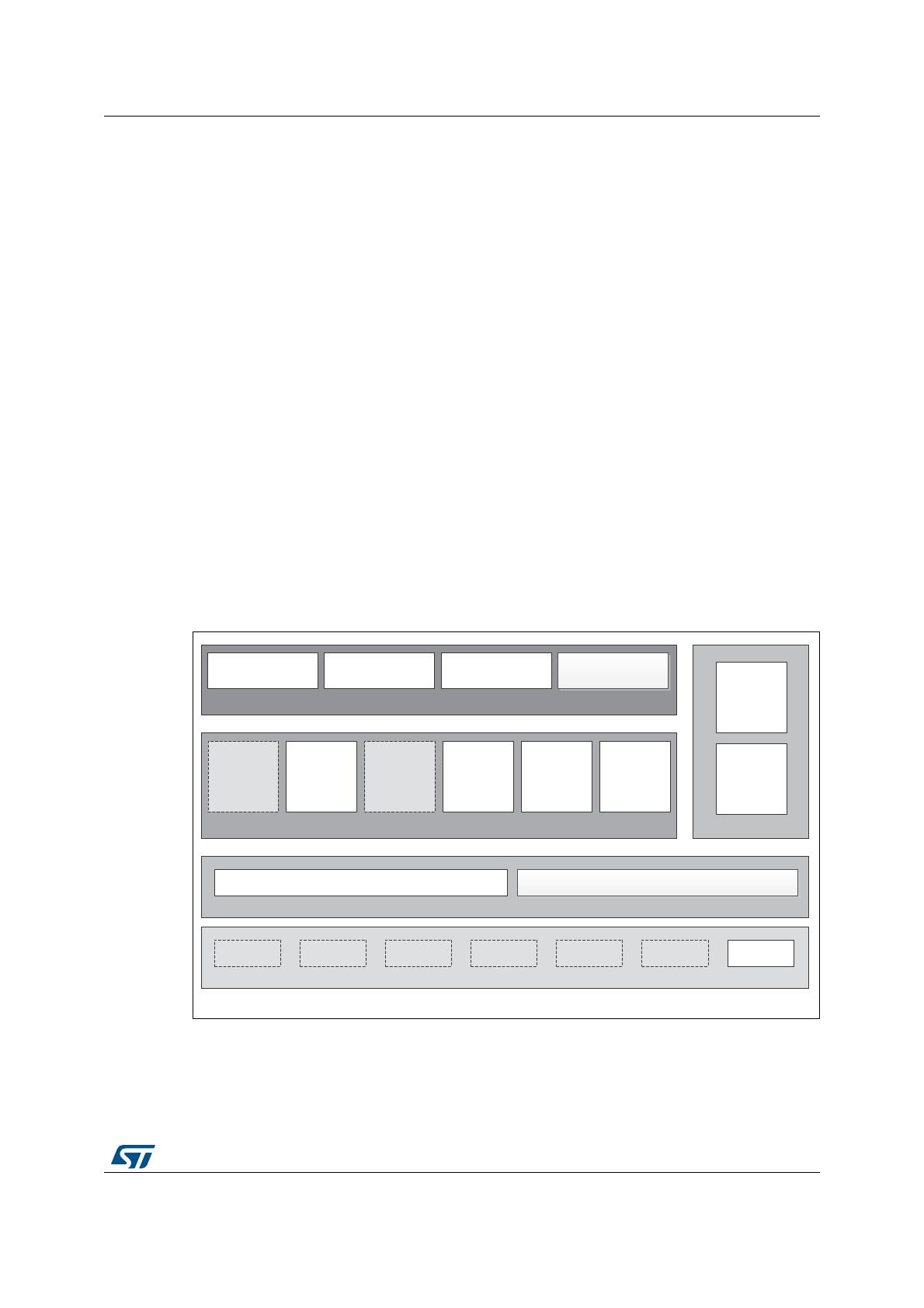
The block diagram of STM32Cube is shown in Figure 1.
Figure 1. STM32Cube block diagram
06Y9
(YDOXDWLRQERDUGV 'LVFRYHU\ERDUGV 6701XFOHR
ERDUGV
7&3,3 86%+RVW
'HYLFH *UDSKLFV )$7ILOH
V\VWHP 5726
8WLOLWLHV
&06,6
670)
+DUGZDUH$EVWUDFWLRQ/D\HU+$/
670) 670) 670) 670) 670/
$SSOLFDWLRQOHYHOGHPRQVWUDWLRQV
8WLOLWLHV0LGGOHZDUHOHYHO
+$/OHYHO
+DUGZDUH
'HGLFDWHGERDUGV
%RDUG6XSSRUW3DFNDJH%63
670/
7RXFK
OLEUDU\
Getting started with the demonstration
6/17 DocID026769 Rev 1
2 Getting started with the demonstration
2.1 Hardware requirements
The hardware requirements to start the demonstration application are as follows:
STM32L053 Discovery board (Figure 2);
One 'USB type A to Mini-B' cable to power up the STM32 Discovery board from the
USB ST-LINK (USB connector CN2);
One ‘USB type A to Mini-B’ cable between CN3 and the PC.
The STM32L053 Discovery kit helps you to discover the ultra-low-power features of the
STM32 L0 series. It offers everything required for beginners and experienced users to get
started quickly and develop applications easily.
Based on an STM32L053C8T6, it includes an ST-LINK/V2-1 embedded debug tool
interface, linear touch sensor, touch keys, Idd current measurement, 2.04” E-paper display,
NFC connector for PLUG-CR95HF-B board, LEDs, pushbuttons and a USB mini-B
connector.
Figure 2. STM32L053 Discovery board (top and bottom views)
DocID026769 Rev 1 7/17
Getting started with the demonstration
16
2.2 Hardware configuration
Check jumpers’ positions on the STM32 Discovery board as follows:
CN4 is set on DISCOVERY mode.
JP4 (IDD) ON.
Demonstration firmware package
8/17 DocID026769 Rev 1
3 Demonstration firmware package
3.1 Demonstration repository
The STM32L053 Discovery demonstration is provided within the STM32CubeL0 firmware
package as shown in Figure 3.
Figure 3. Folder structure
The demonstration sources are located in the projects folder of the STM32Cube package for
the STM32L053C8 Discovery board. The sources are divided into five groups described as
follows:
1. Binary: demonstration binary file in Hex format;
2. Config: contains Touch Sensor, USB and HAL configuration files;
3. Core: contains the demonstration header and source files;
4. Modules: contains source files for Idd measurement and usbHID modules;
5. Project settings: a folder per toolchain containing the project settings and the linker
files.
069
'HPRIROGHU
DocID026769 Rev 1 9/17
Demonstration firmware package
16
3.2 Discovery board BSP
For each board, a set of Button and LEDs drivers is available within the
stm32l0xx_discovery.c/.h files (see Figure 4), implementing the board capabilities and the
bus link mechanism.
Figure 4. Discovery BSP architecture
The EPD is an active Matrix Electrophoretic Display, with interface and a reference system
design. The 2.04” active area contains 172x72 pixels, and has 2-bit full display capabilities.
It uses 2-wire SPI to communicate with the STM32L0 chip.
The SPI peripheral is configured within the stm32l0xx_discovery.c/.h driver which contains
also the SPI bus link mechanism and IO operations.
The EPD is controlled by a dedicated BSP EPD driver stm32_discovery_epd.c/.h which
uses the gde021a1 component that exports in a generic way the EPD IO operations needed
for its process.
Specific fonts are used for displaying characters, the supported ones are:
1. font8;
2. font12;
3. font16;
4. font20.
Demonstration workflow
10/17 DocID026769 Rev 1
4 Demonstration workflow
Figure 5 illustrates the demonstration workflow.
Figure 5. Demonstration diagram
069
6WDUW
'LVSOD\LQJ³670/',6&29(5<'(021675$7,219;<=´PHVVDJHIRUVHFRQGV
%OLQNLQJ/('DQG/('FRQWLQXRXVO\
'LVSOD\WZRLFRQVRQWKH(3'
u86%GHPR
u,GGPHDVXUHPHQWGHPR
&KRRVHRQHGHPR
XVLQJWKH/76 &KRRVHWKH,GGPHDVXUHPHQWGHPR&KRRVHWKH86%GHPR
'LVSOD\D/LQHDUWRXFKLPDJHRQWKH(3'
WRLQGLFDWHWKH86%GHPR
0RYHWKHPRXVHXVLQJWKH/LQHDUVHQVRU 'LVSOD\LFRQVLQGLFDWLQJWKHGLIIHUHQWPRGHV
u5XQPRGH
u6WRSPRGH
u6OHHSPRGH
u/36OHHSPRGH
8VHUEXWWRQ%SUHVVHG"
&KRRVHRQH0&8PRGHXVLQJ/76SRVLWLRQ
5XQPRGH
RU/3PRGH"
'LVSOD\³0&8LQ5XQ0RGH´
PHVVDJHZLWKWKHFXUUHQW
(QWHULQJWKH0&8
LQ/3PRGH
:DLWIRUWKHXVHUEXWWRQWR
JREDFNWRWKHPDLQPHQX
$XWRPDWLF0&8ZDNHXS
'LVSOD\FXUUHQWFRQVXPSWLRQYDOXH
8VHUEXWWRQ%SUHVVHG"
:DLWIRUWKHXVHUEXWWRQWR
JREDFNWRWKHPDLQPHQX
8VHUEXWWRQ%SUHVVHG"
:DLWIRUWKHXVHUEXWWRQWR
JREDFNWRWKHPDLQPHQX
1R
1R
1R
1R
86% ,GG
5XQ /3
<HV
<HV
<HV
<HV
DocID026769 Rev 1 11/17
Demo functional description
16
5 Demo functional description
The STM32L053 Discovery kit demonstration, integrates two major modules: the USB
Demo and the Idd measurement demo.
USB Demo: emulates a USB mouse movement according to the Linear Sensor
position.
Idd measurement Demo: measures and displays in real time the MCU current
consumption depending on the selected power mode. The current is measured and
calculated thanks to a second microcontroller on the board which is STM32 L1 MCU.
5.1 Demo description
After powering the Discovery, the two leds LED3 and LED4 blink continuously. The
message "STM32L053 DISCOVERY DEMONSTRATION VX.Y.Z" (see Figure 6) is
displayed on the e-paper display (EPD) for 2 seconds.
Figure 6. First display screen
Note: VX.Y.Z refers to the demonstration version, example V1.0.1
Then, the EPD screen displays two icons (see Figure 7) indicating the two possible demos.
Figure 7. Main menu screen
The linear touch sensor is used to select the desired demo to run, e.g. upper side for the
USB Demo, lower side for the Idd measurement.
069
670/'HPRQVWUDWLRQ
8VH /76 WR
6HOHFW'HPR
Demo functional description
12/17 DocID026769 Rev 1
5.1.1 USB demo selected
Connect a second USB cable type A to mini-B between CN3 and the PC, then see the
mouse cursor movement according to the linear touch sensor (LTS) position.
Each part of the LTS corresponds to a specific mouse movement direction (Right, Left, Up,
Down), as shown in Figure 8.
Press User Button B1 to go back to the main menu.
Figure 8. USB demo
5.1.2 Idd measurement demo selected
This demo allows the measurement of the Idd values for different power modes, depending
the user selection.
Figure 9 shows, from left to right, the possible power modes supported by this demo, i.e.:
1. Run mode;
2. Sleep mode;
3. Low Power Sleep mode
4. Stop mode.
Figure 9. Idd measurement demo
To select one of the power modes, use the LTS. Each part is associated to a power mode.
Press User button B1 to go back to the main menu.
069
670/86%'HPR
/()75,*+783'2:1
069
670/,'''HPR
%WR([LW
DocID026769 Rev 1 13/17
Demo functional description
16
5.1.3 Run mode selected
If the Run mode is selected, the EPD displays the current consumption, as in Figure 10.
Figure 10. Run mode
To go back to the previous menu, press B1.
5.1.4 Stop mode selected
This section describes Idd measurement in Stop mode, the same behavior applies to the
Sleep and the LPSleep modes.
Before displaying the current consumption in the LP mode, a message to indicate that the
MCU is entering in Stop mode is displayed on the EPD (see Figure 11).
Figure 11. Stop mode
The MCU will be automatically woken up, through an external event EXTI13. This event is
the end of the Idd measurement done on the STM32L1 MCU side. The EPD will display the
view shown in Figure 12, containing the measured current value in real time.
069
%WR([LW
0&8LQ5XQ0RGH
&XUUHQWFRQVXPSWLRQ
9DOXH
069
0&8LQ6WRS0RGH
Demo functional description
14/17 DocID026769 Rev 1
Figure 12. MCU wake-up
To exit this screen and go back to the menu containing the Run and the Low Power modes,
the user has to press button B1.
5.2 Programming firmware application
To program the STM32L053 Discovery board with the demonstration application please
proceed as follows:
1. Install the preferred Integrated Development Environment (IDE).
2. Install the ST-LINK/V2.1 driver available on ST website.
There are two ways of programming the Discovery board:
Upload the STM32L053C8-Discovery_Demo.hex from the firmware package available
under Projects\STM32L053C8-Discovery\Demonstrations\Binary using your preferred in-
system programming tool.
Choose one of two supported tool chains (IAR™ / Keil®) and follow the steps below:
Open the application folder: Projects\STM32L053C8-Discovery\Demonstrations\
Chose the desired IDE project (EWARM for IAR, MDK-ARM for Keil)
Double click on the project file (for example Project.eww for EWARM)
Rebuild all files: Go to Project and select Rebuild all
Load the project image: Go to Project and select Debug
Run the program: Go to Debug and select Go
The demonstration software as well as other software examples that allow you to discover
the STM32 microcontroller features are available on ST website at
www.st.com/stm32discovery.
069
%WR([LW
:DNHXSIURP6WRS
&XUUHQWFRQVXPSWLRQ
9DOXH
DocID026769 Rev 1 15/17
Glossary
16
6 Glossary
EPD: Electronic Paper Display
LTS: Linear Touch Sensor
Revision history
16/17 DocID026769 Rev 1
7 Revision history
Table 1. Document revision history
Date Revision Changes
04-Sep-2014 1 Initial release.
DocID026769 Rev 1 17/17
UM1810
17
IMPORTANT NOTICE – PLEASE READ CAREFULLY
STMicroelectronics NV and its subsidiaries (“ST”) reserve the right to make changes, corrections, enhancements, modifications, and
improvements to ST products and/or to this document at any time without notice. Purchasers should obtain the latest relevant information on
ST products before placing orders. ST products are sold pursuant to ST’s terms and conditions of sale in place at the time of order
acknowledgement.
Purchasers are solely responsible for the choice, selection, and use of ST products and ST assumes no liability for application assistance or
the design of Purchasers’ products.
No license, express or implied, to any intellectual property right is granted by ST herein.
Resale of ST products with provisions different from the information set forth herein shall void any warranty granted by ST for such product.
ST and the ST logo are trademarks of ST. All other product or service names are the property of their respective owners.
Information in this document supersedes and replaces information previously supplied in any prior versions of this document.
© 2014 STMicroelectronics – All rights reserved
  • Page 1 1
  • Page 2 2
  • Page 3 3
  • Page 4 4
  • Page 5 5
  • Page 6 6
  • Page 7 7
  • Page 8 8
  • Page 9 9
  • Page 10 10
  • Page 11 11
  • Page 12 12
  • Page 13 13
  • Page 14 14
  • Page 15 15
  • Page 16 16
  • Page 17 17

STMicroelectronics STM32CubeL0 User manual

Type
User manual

STMicroelectronics STM32CubeL0 offers an STM32 graphical software configuration tool that allows you to generate C initialization code using wizards, encompassing a comprehensive embedded software platform delivered per series (such as STM32CubeL0 for STM32L0 series) with which you can develop your own applications. It includes an STM32CubeL0 HAL, an STM32 abstraction layer embedded software, ensuring maximized portability across STM32 portfolio and a consistent set of middleware components such as RTOS, USB, STMTouch and FatFs, all coming with a full set of examples.

Ask a question and I''ll find the answer in the document

Finding information in a document is now easier with AI