Page is loading ...

Installation & Operation
Manual
Models: ER152, ER202, ER252,
ER302, and ER402
This manual supplies information for the
installation, operation, and servicing of the
appliance. It is strongly recommended that this
manual and the EnergyRite Service Manual be
reviewed completely before proceeding with an
installation. Perform steps in the order given.
Failure to comply could result in severe personal
injury, death, or substantial property damage.
WARNING:
Save this manual for future reference.
ERP-I-O-Rev E

Installation & Operation Manual
Hazard definitions ................................................................................................... 2
Please read before proceeding ............................................................................... 3
Ratings ..................................................................................................................... 5
The EnergyRite -- How it works .............................................................................. 6
1. Determine pool heater location ........................................................................ 8
2. General venting ................................................................................................. 12
3. Conventional venting ........................................................................................ 17
4. Vertical venting ................................................................................................. 19
5. Sidewall venting ................................................................................................ 24
6. Gas connections ............................................................................................... 32
7. Water connections ............................................................................................ 34
8. Electrical connections ...................................................................................... 36
9. Start-up .............................................................................................................. 38
10. Operating information ....................................................................................... 41
Wiring Diagram .......................................................................................... 46
Ladder Diagram ......................................................................................... 47
11. ASME addendum ................................................................................................ 48
The EnergyRite -- How it works_ASME ..................................................... 48
Water connections .................................................................................... 49
Relief valve ................................................................................................ 50
Contents
Hazard definitions
The following defined terms are used throughout this manual to bring attention to the presence of hazards of various risk
levels or to important information concerning the life of the product.
DANGER
WARNING
CAUTION
CAUTION
NOTICE
DANGER indicates an imminently hazardous situation which, if not avoided, will result in death or
serious injury.
WARNING indicates a potentially hazardous situation which, if not avoided, could result in death or
serious injury.
CAUTION indicates a potentially hazardous situation which, if not avoided, may result in minor or
moderate injury.
CAUTION used without the safety alert symbol indicates a potentially hazardous situation which, if not
avoided, may result in property damage.
NOTICE indicates special instructions on installation, operation, or maintenance that are important but
not related to personal injury or property damage.
2

Installation & Operation Manual
3
Please read before proceeding
NOTICE
This is a gas appliance and should be
installed by a licensed electrician and/or
certified gas supplier. Service must be
performed by a qualified service installer,
service agency or the gas supplier.
WARNING
If the information in these instructions is
not followed exactly, a fire or explosion
may result causing property damage,
personal injury, or death.
This pool heater MUST NOT be
installed in any location where gasoline
or flammable vapors are likely to be
present, unless the installation is such
to eliminate the probable ignition of
gasoline or flammable vapors.
What to do if you smell gas –
• Do not try to light any appliance.
• Do not touch any electric switch; do not use any
phone in your building.
• Immediately call your gas supplier from a neighbors
phone. Follow the gas supplier’s instructions.
• If you cannot reach your gas supplier, call the fire
department.
Installation and service must be performed by a qualified
installer, service agency, or the gas supplier.
Warranty –
Factory warranty (shipped with unit) does not apply to
units improperly installed or improperly operated.
Experience has shown that improper installation or system
design, rather than faulty equipment, is the cause of most
operating problems.
1. Improper maintenance of pool water chemistry
resulting in high water hardness and high alkalinity that
results in a lime scale build up in the copper tube is not
the fault of the equipment and is not covered under the
manufacturer’s warranty (see the Facts About Water
Chemistry section of the EnergyRite Service Manual).
2. Excessive pitting and erosion on the inside of the
copper tube may be caused by too much water velocity
through the tubes and is not covered by the
manufacturer’s warranty (see Water Connections,
Table 7A - Minimum Water Flow Requirements).
Checking equipment –
Upon receiving equipment, check for signs of shipping damage.
Pay particular attention to parts accompanying the pool
heater which may show signs of being hit or otherwise being
mishandled. Verify total number of pieces shown on packing
slip with those actually received. In case there is damage or a
shortage, immediately notify the carrier.
Do not use this pool heater if any part has been under water.
The possible damage to a flooded pool heater can be extensive
and present numerous safety hazards. Any pool heater that
has been under water must be replaced.
WARNING
Improper installation, adjustment, alteration,
service or maintenance can cause injury or
property damage. Refer to this manual for
assistance or additional information, consult
a qualified installer, service agency or the gas
supplier.
Owner warning –
The information contained in this manual is intended for use
by qualified professional installers, service technicians, or gas
suppliers. Consult your local expert for proper installation or
service procedures.
NOTICE
Consult and follow all local Building and
Fire Regulations and other Safety Codes that
apply to this installation. Consult a local gas
utility company to authorize and inspect all
gas and flue connections.
Your conventionally vented gas unit must have a supply of fresh
air circulating around it during burner operation for proper gas
combustion and proper venting.
WARNING
Should overheating occur or the gas supply
fail to shut off, do not turn off or disconnect
the electrical supply to the pump. Instead,
turn off the manual gas control valve to
the appliance at a location external to the
appliance.
Prevention of freezing –
Heat exchangers and headers damaged by freezing are not
covered by warranty.
See the Winterizing section of the EnergyRite Service Manual.

4
Installation & Operation Manual
Please read before proceeding
Spa and hot tub safety –
The following safety rules must be observed while operating
spa or hot tub.
1. Spa or hot tub water temperatures should never exceed
104°F (40°C). A temperature of 100°F (38°C) is
considered safe for a healthy adult. Special caution is
suggested for young children.
2. Drinking of alcoholic beverages before or during spa or
hot tub use can cause drowsiness which could lead to
unconsciousness and subsequently result in drowning.
3. Pregnant women beware! Soaking in water above 102°F
(39°C) can cause fetal damage during the first three
months of pregnancy (resulting in birth of a brain-
damaged or deformed child). Pregnant women should
observe the 100°F (38°C) maximum rule.
4. Before entering the spa or hot tub, users should check
the water temperature with an accurate thermometer;
spa or hot tub thermostats may err in regulating water
temperatures by as much as 4°F (2°C).
5. Persons with a medical history of heart disease,
circulatory problems, diabetes or blood pressure
problems should obtain their physician’s advice before
using spas or hot tubs.
6. Persons taking medications which induce drowsiness,
such as tranquilizers, antihistamine or anticoagulants,
should not use spas or hot tubs.
WARNING
To minimize the possibility of serious personal
injury, fire, or damage to your pool heater,
never violate the following safety rules:
1. Pool heaters are heat producing
appliances. To avoid damage or injury,
do not store materials against the pool
heater or the vent-air intake system.
Use proper care to avoid unnecessary
contact (especially children) with the
pool heater and vent-air intake
components.
2. Never cover your pool heater, lean
anything against it, store trash or debris
near it, stand on it or in any way block
the flow of fresh air to your pool heater.
3. UNDER NO CIRCUMSTANCES must
flammable materials such as gasoline or
paint thinner be used or stored in the
vicinity of this pool heater, vent-air
intake system or any location from
which fumes could reach the pool
heater or vent-air intake system.
Codes –
This pool heater has been designed and certified under the latest
edition of Z21.56/CSA 4.7 Gas Fired Pool Heater Standard,
including applicable addenda.
The pool heater shall be installed in accordance with those
installation regulations in force in the local area where the
installation is to be made. These shall be carefully followed in all
cases. Authorities having jurisdiction shall be consulted before
installations are made. In the absence of such requirements,
the installation shall conform to the latest edition of the
National Fuel Gas Code, ANSI Z223.1 and/or CAN/CGA-B149
Installation Code.
As an option, all pool heaters may be ordered with heat
exchanger construction that conforms to the latest edition of
the ASME Boiler and Pressure Vessel Code, Section IV, Part
HLW.

Installation & Operation Manual
Ratings
5
HLW
Notes:
1. The ratings are based on standard test procedures prescribed
by the United States Department of Energy.
2. Use only the vent materials and methods specified in
the Venting Section of the EnergyRite Installation and
Operation Manual.
3. This appliance is equipped for operation up to 2000 feet, and
including up to 4000 feet, with no field adjustments. The
appliance output ratings up to 4000 feet shall be reduced by
4% for each 1000 feet above sea level. For operation above
4000 feet, consult the factory. For operation above 2000
feet in Canada, consult the factory.
Model Number
Note: Change “N” to
“L” for Propane gas
models.
Add suffix “-A” for
ASME models.
Input
Btu/hr
Pool Heater Water Content
Gallons
Gas
Connections Vent/Air Size Maximum Working Pressure
(PSI)
(Note 3)
ASME NON-ASME
(NPT)
Conventional
DirectAire
(Note 2)
E-Rite
(Note 2)
ASME NON-ASME
ERN152 150,000 0.58 0.83 3/4" 5" 4" 4" 125 50
ERN202 199,999 0.58 0.84 3/4" 5" 4" 4" 125 50
ERN252 250,000 0.59 0.84 3/4" 6" 5" 5" 125 50
ERN302 300,000 0.59 0.85 3/4" 6" 5" 5" 125 50
ERN402 399,999 0.60 0.85 3/4" 6" 6" 6" 125 50

Installation & Operation Manual
6
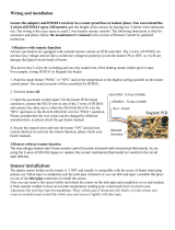
The EnergyRite - How it works...
1. Heat exchanger
Allows pool water to flow through specially designed
tubes for maximum heat transfer, while providing protection
against flue gas corrosion.
2. Blower
The blower provides air to mix with gas in the burners.
3. Gas valve
The gas valve is a single stage referencing valve. The valve senses
the chamber pressure and regulates gas flow based on that signal.
4. Outlet temperature sensor
This sensor monitors outlet water temperature and will shut
down the unit if this temperature gets too high.
5. Inlet temperature sensor
This sensor monitors the inlet water temperature and will be
used by the integrated control to determine whether an
ignition cycle should begin.
6. Electronic display
The electronic display consists of 4 buttons and a dual line
32-character liquid crystal display.
7. Burner
The burner is a stainless steel burner which accepts both gas
and air and mixes them. The number of burners in the unit
depends on the Btu input: 150,000 Btu/hr = 3;
199,999 Btu/hr = 4; 250,000 Btu/hr = 5; 300,000 Btu/hr = 6; and
399,999 Btu/hr = 8.
8. Water outlet (pool supply)
For a standard unit this is a 2” slip fit connection with
supplied union nuts and a starter pipe assembly. For an
ASME unit, see the ASME section of this manual.
9. Water inlet (pool return)
For a standard unit this is a 2” slip fit connection with
supplied union nuts and a starter pipe assembly. For an
ASME unit, see the ASME section of this manual.
10. Water pressure switch boot
The water pressure switch boot provides protection for the water
pressure switch.
11. Control Module
The control responds to internal and external signals
and controls the blower, and gas valve to meet the
heating demand.
12. High voltage junction box
The junction box contains the connection points for the line
voltage power.
13. Pool heater drain port (not shown)
Location from which the heat exchanger can be drained.
14. Low voltage terminal strip
The terminal strip is used to connect proving switch contacts and
a third party remote.
15. Ignition electrode
Provides direct spark for igniting the burner.
16. Flame inspection window
The quartz glass window provides a view of the burner
surface and flame.
17. High limit sensor
Device that monitors the outlet water temperature. If the
temperature exceeds 175°, it will break the control circuit, shutting
the pool heater down.
18. Flame sensor
Used by the control module to detect the presence of burner
flame.
19. Top panel
Removable panel to gain access to the internal components.
20. Power switch
Turns line power (120 or 240 VAC) ON/OFF to the pool heater.
21. Outdoor vent cap
An outdoor vent cap is mounted on the pool heater as shipped
from the factory.
22. Water pressure switch
The water pressure switch is a safety device that ensures the heat
exchanger is under pressure. If the water pressure in the heat
exchanger goes too low, it will break the control circuit, shutting
the pool heater down.
23. Air pressure switch
The air pressure switch is a safety device that ensures proper
blower performance through the heater before and during
operation. This device also detects blockages in the vent or air
piping.
24. 240 VAC - 120 VAC conversion
This appliance is wired for 240 VAC service. The pool heater can
be converted to 120 VAC by moving the jumper connector from
the connector labeled 240 VAC to the connector labeled 120 VAC.
25. Low gas pressure switch (ER252 - ER402 Models ONLY)
Ensures adequate gas pressure is provided to the pool heater.

Installation & Operation Manual
The EnergyRite - How it works... (continued)
7
Front View
Left Side (inside unit)
Right Side (inside unit)
Rear View
Models ER152 - ER402

Installation & Operation Manual
8
1 Determine pool heater location
Location of pool heater
1. Locate the pool heater so that if water connections should
leak, it will not result in damage to the area adjacent to
the pool heater or to the structure. When such locations
cannot be avoided, it is recommended that a suitable drain
pan, adequately drained, be installed under the pool heater.
The pan must not restrict combustion air flow. Under no
circumstances is the manufacturer to be held responsible for
water damage in connection with this pool heater, or any of
its components.
2. Pool heaters located in a residential garage and in adjacent
spaces that open to the garage and are not part of the living
space of a dwelling unit must be installed so that all burners
and burner ignition devices have a minimum clearance of
not less than 18” (46 cm) above the floor. The pool heater
must be located or protected so that it is not subject to
physical damage by a moving vehicle.
3. DO NOT install this pool heater in any location where
gasoline or flammable vapors are likely to be present.
4. DO NOT install this pool heater on carpet.
5. This pool heater is approved for installation on combustible
(wood) flooring.
6. Outdoor models are factory supplied with an outdoor
vent cap assembly. Outdoor models must not be installed
directly on the ground. A suitable rigid and level base such
as concrete, brick, or other stable surface that will ensure
stability of the pool heater. Outdoor models have additional
special location and clearance requirements. These are
specifically addressed in the Venting Section under Outdoor
Installation. Do not install in locations where rain from
building runoff drains or sprinkler systems will spill onto the
pool heater. A windproof cabinet protects the pool heater
from weather.
7. Indoor installations require that the factory installed outdoor
vent cap be removed from the pool heater to allow the
installation of a flue pipe. Specific instructions for the
removal of the outdoor cap are addressed in the Venting
section. Indoor installations require an adequate supply
of clean combustion air for proper operation. Optional
venting arrangements may allow direct pipe connection from
the pool heater to the outside for combustion air. See the
Venting Options section of this manual.
8. This pool heater must be installed at least five feet from
the inside wall of a pool unless separated from the pool by
a solid fence, wall or permanent barrier.
9. When a pool heater is installed within the pool structure, the
structure shall be designed such that in the event of a fuel
gas leak, the leaking gas is vented to the exterior of the pool
structure.

Installation & Operation Manual
1 Determine pool heater location (continued)
9
Figure 1-1_Clearances from Combustible Construction
(Front and Rear)
Combustion and ventilation air
requirements for conventionally
vented appliances and sidewall
vented appliances
Provisions for combustion and ventilation air must
be in accordance with the Air for Combustion and
Ventilation Section of the latest edition of the National
Fuel Gas Code, ANSI Z223.1, in Canada CAN/CGA-
B149 Installation Code for Gas Burning Appliances
and Equipment, or applicable provisions of the local
building codes.
The equipment room MUST be provided with properly
sized openings to assure adequate combustion air and
proper ventilation when the pool heater is installed
with conventional venting or sidewall venting and
drawing combustion air from the room.
TABLE - 1A
CLEARANCES FROM COMBUSTIBLE CONSTRUCTION
Location Clearances
Right Side 3” (24” suggested for service)
Rear (Outdoor) 3” (3” minimum from any surface)
Rear (Indoor) 6” (6” minimum from any surface)
Left Side 3”
Front - Alcove* Open (24” suggested for service)
Top 3” (24” suggested for service)
Flue (Indoor) 6”
Hot Water Pipes 1”
*An Alcove is a closet without a door.
Figure 1-2_Combustion Air Direct from Outside
1. If air is taken directly from outside the building with
no duct, provide two permanent openings to the
equipment room:
(a) Combustion air opening, with a minimum free
area of one square inch per 4000 Btu/hr input. This
opening must be located within 12” of the bottom of
the floor.
(b) Ventilation air opening, with a minimum free area
of one square inch per 4000 Btu/hr input. This
opening must be located within 12” of the top of the
ceiling.

Installation & Operation Manual
10
1 Determine pool heater location
Figure 1-3_Combustion Air Through Ducts
2. If combustion and ventilation air is taken from the
outdoors using a duct to deliver the air to the equipment
room, each of the two openings should be sized based on a
minimum free area of one square inch per 2000 Btu/hr.
Figure 1-4_Combustion Air from Interior Space
3. If air is taken from another interior space, each of the two
openings specified above should have a net free area of one
square inch for each 1000 Btu/hr of input, but not less than
100 square inches.
Figure 1-5_Combustion Air from Outside - Single
Opening
4. If a single combustion air opening is provided to bring
combustion air in directly from the outdoors, the
opening must be sized based on a minimum free area
of one square inch per 3000 Btu/hr. This opening must be
located within 12” of the top of the ceiling.

Installation & Operation Manual
1 Determine pool heater location (continued)
11
Combustion air requirements are based on the latest edition
of the National Fuel Gas Code, ANSI Z223.1, in Canada CAN/
CGA-B149 Installation Code for Gas Burning Appliances and
Equipment. Check all local code requirements for combustion
air.
All dimensions are based on net free area in square inches.
Metal louvers or screens reduce the free area of a combustion air
opening a minimum of approximately 25%. Check with louver
manufacturers for exact net free area of louvers. Where two
openings are provided, one must be within 12” of the ceiling
and one must be within 12” of the floor of the equipment room.
Each opening must have net free area as specified in Table 1B.
Single openings shall be installed within 12” of the ceiling.
CAUTION
Under no circumstances should the
equipment room ever be under a negative
pressure. Particular care should be taken
where exhaust fans, attic fans, clothes
dryers, compressors, air handling units, etc.,
may take away air from the unit.
The combustion air supply must be
completely free of any flammable vapors
that may ignite or chemical fumes which
may be corrosive to the pool heater.
Common corrosive chemical fumes which
must be avoided are fluorocarbons and
other halogenated compounds, most
commonly present as refrigerants or
solvents, such as Freon, trichlorethylene,
perchlorethylene, chlorine, etc. These
chemicals, when burned, form acids which
attack the heat exchanger finned tubes,
headers, flue collectors, and the vent system.
The result is improper combustion and a
non-warrantable, premature pool heater
failure.
EXHAUST FANS: Any fan or equipment which exhausts
air from the equipment room may deplete the combustion
air supply and/or cause a downdraft in the venting system.
Spillage of flue products from the venting system into an
occupied living space can cause a very hazardous condition
that must be immediately corrected. If a fan is used to
supply combustion air to the equipment room, the installer
must make sure that it does not cause drafts which could
lead to nuisance operational problems with the pool heater.
DirectAire Vertical, DirectAire Horizontal and E-Rite
Venting systems have specific requirements for combustion
air ducts from the outside which are directly connected to
the pool heater. See the requirements for this combustion
air duct in the Venting section for each specialized vent
system.
TABLE - 1B
MINIMUM RECOMMENDED COMBUSTION
AIR SUPPLY TO EQUIPMENT ROOM
Model
Number
Outside Air from
2 Openings Directly from
Outdoors
Outside Air from
1 Opening Directly
from Outdoors, in
2
Inside Air from
2 Ducts Delivered from
Outdoors
Inside Air from
2 Ducts Delivered from
Interior Space
Top
Opening, in
2
Bottom
Opening, in
2
Top
Opening, in
2
Bottom
Opening, in
2
Top
Opening, in
2
Bottom
Opening, in
2
ER152 38 38 50 75 75 150 150
ER202 50 50 67 100 100 200 200
ER252 63 63 83 125 125 250 250
ER302 75 75 100 150 150 300 300
ER402 100 100 133 200 200 400 400

Installation & Operation Manual
12
2 General venting
Figure 2-1_Conventional Negative Draft Venting -
See page 17 for more details
Figure 2-3_DirectAire Vertical Venting w/Vertical
Air Inlet - See page 20 for more details
Figure 2-4_Power Sidewall Venting - See page 24 for
more details
Vent system options
Figure 2-2_DirectAire Vertical w/Sidewall Air Inlet -
See page 21 for more details

Installation & Operation Manual
2 General venting (continued)
13
Figure 2-6_E-Rite Sidewall Venting - See page 27
for more details
Figure 2-7_Outdoor Venting - See page 14 for
more details
This pool heater has six (6) venting options. They are: (1)
Conventional Negative Draft Venting with vertical rooftop
flue termination and combustion air supplied from the
equipment room, (2) DirectAire Vertical Venting with a
vertical conventional vent for flue products and a combustion
air pipe from either the sidewall or rooftop, (3) Power Sidewall
Venting to exhaust flue products out a sidewall with a powered
vent assembly and combustion air supplied from the equipment
room (4) DirectAire Horizontal Venting with a powered
vent assembly to exhaust the flue products out a sidewall and
a combustion air pipe from the sidewall, (5) E-Rite Sidewall
Venting which uses the internal combustion air fan to exhaust
the flue products out a sidewall vent termination with a
limited vent length. Combustion air for an E-Rite Sidewall
vent must be supplied with a combustion air pipe from the
sidewall, (6) Outdoor Venting using the factory supplied
vent cap installed on the unit. All pool heaters are shipped
from the factory equipped for Outdoor Installation. All other
optional vent systems require the removal of the outdoor vent
cap and installation of specific vent kits and venting materials.
The following is a detailed explanation of the installation
requirements for each venting system, components used and
part numbers of vent kits for each model.
Figure 2-5_Power DirectAire Horizontal Venting - See
page 25 for more details

Installation & Operation Manual
14
2 General venting
Vent connection is made directly to the flue outlet connection
on the pool heater. No additional draft diverter or barometric
damper is required on single unit installations when a negative
draft is maintained within the specified range. The connection
from the pool heater’s vent to the stack must be made as direct
as possible.
Barometric damper location
The preferred location for the barometric damper (if required)
is in a tee or collar installed in the vertical pipe, rising from the
pool heater’s flue outlet. The barometric damper must not be
installed in a bullhead tee installed on the unit’s flue outlet.
The tee or collar containing the barometric damper should be
approximately three feet vertically above the connection to the
unit’s flue outlet. This location ensures that any positive velocity
pressure from the unit’s internal combustion fan is dissipated
and the flue products are rising due to buoyancy generated from
the temperature of the flue products. Adjust the weights on the
damper to ensure that draft is maintained within the specified
range.
Examine the venting system at least once
a year. Check all joints and vent pipe
connections for tightness. Also check for
corrosion or deterioration. Immediately
correct any problems observed in the venting
system.
NOTICE
Outdoor installation
Units are self venting and can be used outdoors when installed
with the factory supplied outdoor vent cap. The outdoor
vent cap is mounted directly to the rear of the pool heater as
shipped from the manufacturer and covers the flue outlet and
combustion air inlet openings on the jacket. No additional vent
piping is required.
WARNING
The flue products discharged from the flue
outlet on the outdoor vent cap may be very
hot. Avoid touching or other direct contact
with the flue gases or the vent cap assembly.
These components are hot and direct contact
can result in burns.
WARNING
Outdoor models must be installed outdoors
and must use the outdoor vent cap assembly
supplied by the manufacturer. Personal
injury or product damage may result if any
other cap is used or if an outdoor model is
used indoors. All covers, doors, and jacket
panels must be properly installed to ensure
proper operation and prevent a hazardous
condition.
CAUTION
Pool heaters which are shut down or will
not operate may experience freezing due
to convective air flow in the outdoor vent
cap installed on the unit. If operated in
cold climates, continuous pump operation
is recommended to help prevent freezing of
pool water in an outdoor installation. Proper
freeze protection must be provided. A pool
heater that is not in use in the winter season
must be properly drained and winterized.
See the Winterizing section of the EnergyRite
Service Manual.
Combustion air supply must be free of contaminants (see
Combustion and Ventilation Air Requirements in the Determine
Pool Heater Location section). To prevent recirculation of
the flue products into the combustion air inlet, follow all
instructions in this section.
The venting areas must never be obstructed. Keep area clean
and free of combustible and flammable materials. Maintain a
minimum clearance of 3 inches to combustible surfaces and
a minimum of a 3 inch clearance to the air inlet. To avoid a
blocked air inlet or blocked flue condition, keep the outdoor
cap air inlet, flue outlet and drain slot clear of leaves, debris,
snow, ice, etc.
A pool heater should not be located so that high winds
can deflect off of adjacent walls, buildings, or shrubbery
causing recirculation. Recirculation of flue products may cause
operational problems, bad combustion or damage to controls.
The pool heater should be located at least 3 feet from any wall
or vertical surface to prevent adverse wind conditions from
affecting performance.
General
Vent installations for connection to gas vents or chimneys must
be in accordance with “Venting of Equipment”, of the latest
edition of the National Fuel Gas Code, ANSI Z223.1, in Canada,
the latest edition of CAN/CGA - B149 Installation Codes for Gas
Burning Appliances and Equipment or applicable provisions of
the local building codes.
Conventional negative draft venting and sidewall venting
applications, where outside air is used, must have adequate
combustion and ventilation air supplied to the equipment
room in accordance with the latest edition of the National Fuel
Gas Code, ANSI Z223.1, in Canada, the latest edition of CAN/
CGA - B149 Installation Codes for Gas Burning Appliances and
Equipment, or applicable provisions of the local building codes.
The distance of the vent terminal from adjacent buildings,
windows that open and building openings, MUST comply with
the latest edition of the National Fuel Gas Code, ANSI Z223.1,
in Canada, the latest edition of CAN/CGA - B149 Installation
Codes for Gas Burning Appliances and Equipment.

Installation & Operation Manual
2 General venting (continued)
15
The outdoor pool heater must not be installed in an area
that is enclosed by walls or a fence that will block free wind
movement around the pool heater. Free movement of
wind around the outdoor unit is required to carry away the
flue products and provide combustion air. The flue outlet/
combustion air inlet cap of an outdoor pool heater must
not be installed closer than 10 feet from an inside corner of
an L-shaped structure. Walls or enclosed fencing may cause
eddy currents which can recirculate the flue products into
the combustion air inlet. Recirculation of flue products
may cause operational problems, bad combustion or non-
warrantable damage to controls.
Do not install the pool heater with outdoor venting under
a deck.
Do not install an outdoor pool heater in a well, stairwell,
alcove, courtyard, or other recessed area.
The outdoor unit must be located 4 feet below and 4 feet
horizontally from any window, door, walkway, or gravity
air intake.
The combustion air inlet of the outdoor cap must be
located at least 1 foot above grade and above normal snow
levels. The pool heater must be at least 10 feet away from
any forced air inlet.
The pool heater must be at least 3 feet outside any overhang.
Clearances around outdoor installations can change with
time. Do not allow the growth of trees, shrubs, or other
plants to obstruct the proper operation of the outdoor vent
system.
Do not install in locations where rain from building runoff
drains will spill onto the pool heater.
Do not locate the pool heater so that water from sprinklers
may spray directly on the unit. Water may damage controls
or other electrical components.
Multiple unit outdoor pool heater installations require a
minimum of 4 feet clearance between the vent cap and air
inlet of adjacent heaters to prevent recirculation of flue
products.
Flue gas condensate can freeze on exterior walls or on the
vent cap of a pool heater operated in the winter months.
Frozen condensate on the vent cap can result in a blocked
flue condition. Some discoloration to exterior building or
unit surfaces can be expected. Adjacent brick or masonry
surfaces should be protected with a rust resistant sheet
metal plate.
Figure 2-8_Outdoor Vent Cap (Outside View)
Figure 2-9_Outdoor Vent Cap Installed on Unit
The outdoor vent cap
An outdoor vent cap is furnished by the manufacturer in
accordance with CSA International requirements. An outdoor
vent cap kit is mounted on the pool heater as shipped from the
factory. The kit includes the flue outlet/combustion air inlet
assembly and gasket.
CAUTION
Pool heaters which are shut down or will
not operate may experience freezing due
to convective air flow through the vent
cap installed on the unit. Proper freeze
protection must be provided. A pool heater
that is not in use in the winter season must
be properly drained and winterized. See the
Winterizing section of the EnergyRite Service
Manual.

Installation & Operation Manual
16
2 General venting
WARNING
An Outdoor Installation, DirectAire Vent or
an E-Rite Vent into dead air spaces such as
alleys, atriums, and inside corners can cause
recirculation of flue gases. Recirculation of
flue gases will cause incomplete combustion,
sooting, premature failure of the jacket, vent
and heat exchanger as well as icing of the
combustion air intake during operation in
severe cold weather. Minimum clearances
between the combustion air intake and
exhaust vent terminal are specified in
the installation instructions. To prevent
recirculation of the flue gases, maintain
as much distance as possible between the
combustion air intake and the exhaust vent
terminal.
Failure to comply with the above could
result in severe personal injury, death or
substantial property damage.
Figure 2-10_Removal of Outdoor Vent Cap
GASKET
FLUE TRANSITION
ASSEMBLY
INLET AIR
COLLAR
IMG00217
Figure 2-11_Installation of Flue Adapter and Air Inlet Collar
Installation of optional vent kits
GASKET
IMG00217
FLUE TRANSITION
A
SSEMBLY
AIR INLET
COVER
Figure 2-12_Installation of Flue Adapter and Air Inlet
Cover
Whenever a vent option other than outdoor installation is
desired, the outdoor vent cap assembly must be removed and an
optional vent kit must be installed on the pool heater. The vent
kit allows connection of the flue and/or a combustion air pipe.
The vent kit includes the flue adapter*, assembly instructions
and an air inlet collar to allow connection of an air inlet pipe
or an air inlet cover when combustion air is drawn from the
equipment room. Remove the screws surrounding the outdoor
vent cap and the four screws in the divider between the flue
outlet and air inlet chambers on the vent cap.
*A flue adapter is not provided in the E-Rite Vent Kit.

Installation & Operation Manual
3 Conventional venting
17
Figure 3-1_Conventional Negative Draft Vertical
Venting with Combustion Air Louvers
A conventional negative draft venting system
The outdoor vent cap assembly must be removed before any
connection to a conventional negative draft vent system can
be made. A conventional vent adapter kit must be installed
on the pool heater’s flue outlet. The conventional vent kit
includes the flue adapter and an air inlet cover. Mount the
air inlet cover over the combustion air inlet opening on the
rear of the jacket. No additional draft diverter or barometric
damper is required on single unit installations with a
dedicated stack and a negative draft within the specified
range of a negative 0.02 to 0.08 inches water. If the draft in
a dedicated stack for a single unit installation exceeds the
maximum specified draft, a barometric damper must be
installed to control draft. Multiple unit installations with
combined venting or common venting of this pool heater
with other Category I negative draft appliances requires that
each pool heater must have a barometric damper installed
to regulate draft within the proper range.
TABLE - 3A
CONVENTIONAL VENT DATA
Model
Number
Conventional Vent
Flue Size
Conventional Vent
Kit Number
ER152 5” CVK3004
ER202 5” CVK3004
ER252 6” CVK3005
ER302 6” CVK3006
ER402 6”* CVK3006
The negative draft in a conventional vent installation must
be within the range of a negative 0.02 to 0.08 inches water
to ensure proper operation. All draft readings are made
while the unit is in stable operation (approximately 2 to
5 minutes). Remember that the draft in a conventional
negative draft vent may vary seasonally. A pool heater
with a high draft when operating in the winter months
may have a much lower draft in the summer. Initial
set-up of a vent system with a draft of not more than
a negative 0.05 inches water will generally ensure that
increased draft in the winter months will not exceed the
specified maximum. Maximum draft can not exceed a
negative 0.08 inches of water.
On a conventionally vented, negative draft pool heater, the
connection from the vent to the stack or vent termination
outside the building must be made with listed Type “B”
double-wall (or equivalent) vent connectors and must be
direct as possible with no reduction in diameter. Use the
National Fuel Gas Code venting tables for double-wall
vent to properly size all vent connectors and stacks. The
Type “B” vent and accessories, such as firestop spacers,
thimbles, caps, etc., must be installed in accordance with
the manufacturer’s instructions. The vent connector and
firestop must provide correct spacing to combustible
surfaces and seal to the vent connector on the upper and
lower sides of each floor or ceiling through which the vent
connector passes.
Any vent materials specified must be listed by a nationally
recognized test agency for use as vent material.
Locate the pool heater as close as practicable to chimney
or gas vent.
Avoid long horizontal runs of the vent pipe, 90° elbows,
reductions and restrictions. Horizontal portions of the
venting system shall be supported to prevent sagging.
Horizontal runs must slope upwards not less than 1/4 inch
per foot from the appliance to the vent terminal.
Do not use an existing chimney as a raceway for a flue
pipe if another appliance or fireplace is vented through
the chimney.
The weight of the venting system must not rest on the
unit. Adequate support of the venting system must
be provided in compliance with local codes and other
applicable codes. All connections should be secured with
rustproof sheet metal screws.
Vent connectors serving appliances vented by natural
draft MUST NOT be connected to any portion of a
mechanical draft system operating under positive pressure.
Connection to a positive pressure stack may cause flue
products to be discharged into the living space causing
serious health injury.
*On the ER402 model you MUST have at least 8 feet of
vertical vent to use a 6” vent , if less than 8 feet the vent size
must increase to 7”.

18
Installation & Operation Manual
3 Conventional venting
Common venting systems may be too large when an existing
unit is removed. At the time of removal of an existing appliance,
the steps below shall be followed with each appliance remaining
connected to the common venting system placed in operation,
while other appliances remaining connected to the common
venting system are not in operation.
a. Seal any unused opening in the common venting
system.
b. Visually inspect the venting system for proper size
and horizontal pitch and determine there is no
blockage or restriction, leakage, corrosion and
other unsafe condition.
c. Insofar as is practical, close all building doors and
windows and all doors between the space in which
the appliances remaining connected to the
common venting system are located and other
spaces of the building. Turn on clothes dryers and
any other appliances not connected to the
common venting system. Turn on any exhaust
fans, such as range hoods and bathroom exhausts,
so they will operate at maximum speed. Do not
operate a summer exhaust fan. Close fireplace
dampers.
d. Place in operation the appliance being inspected.
Follow the operating instructions on page 38 of this
manual. Adjust thermostat so appliance will operate
continuously.
e. After it has been determined that each appliance
remaining connected to the common venting
system properly vents when tested as above, return
doors, windows, exhaust fans, fireplace dampers,
and other gas burning appliances to their previous
conditions of use.
f. Any improper operation of the common venting
system should be corrected so that the installation
conforms to the latest edition of the National Fuel
Gas Code, ANSI Z223.1, in Canada, the latest
edition of CAN/CGA - B149 Installation Codes for
Gas Burning Appliances and Equipment. When
resizing any portion of the common venting
system, the common venting system should be
resized to approach the minimum size as
determined using the appropriate tables in the
latest edition of the National Fuel Gas Code,
ANSI Z223.1, in Canada, the latest edition of
CAN/CGA - B149 Installation Codes for Gas
Burning Appliances and Equipment.

Installation & Operation Manual
4 Vertical venting
19
Figure 4-1_Vent Termination from Peaked Roof -
10 Feet or Less From Ridge
Vertical venting termination
Figure 4-3_Vent Termination from Peaked Roof
More Than 10 Feet From Ridge
The vent terminal should be vertical and exhaust outside
the building at least 2 feet above the highest point of the
roof within a 10 foot radius of the termination.
The vertical termination must be a minimum of 3 feet
above the point of exit.
Figure 4-2_Vent Termination from Flat Roof 10 Feet
or Less from Parapet Wall
Figure 4-4_Vent Termination from Flat Roof More
Than 10 Feet from Parapet Wall
A vertical termination less than 10 feet from a parapet wall must
be a minimum of 2 feet higher than the parapet wall.
The vent cap should have a minimum clearance of 4 feet
horizontally from and in no case above or below, unless a 4
foot horizontal distance is maintained from electric meters, gas
meters, regulators, and relief equipment.
The venting system shall terminate at least 3 feet above any
forced air inlet within 10 feet.

Installation & Operation Manual
20
4 Vertical venting
The venting system shall terminate at least 4 feet below, 4 feet
horizontally from, or 1 foot above any door, window, or gravity
air inlet into any building.
Do not terminate the vent in a window well, stairwell, alcove,
courtyard, or other recessed area. The vent cannot terminate
below grade. The bottom of the vent terminal shall be located
at least 12 inches above grade.
To avoid a blocked flue condition, keep the vent cap clear of
snow, ice, leaves, debris, etc. Flue gases will form a white plume
in winter. Plume could obstruct window view.
Flue gas condensate can freeze on exterior surfaces or on the
vent cap when a pool heater is operated in the winter months.
Frozen condensate on the vent cap can result in a blocked flue
condition. Flue gas condensate can cause discoloration of
exterior building surfaces. Adjacent brick or masonry surfaces
should be protected with a rust resistant sheet metal plate.
Masonry chimney installation
A masonry chimney must be properly sized for the installation of
a high efficiency gas fired appliance. Venting of a high efficiency
appliance into a cold or oversized masonry chimney can result
in operational and safety problems. Exterior masonry chimneys,
with one or more sides exposed to cold outdoor temperatures,
are more likely to have venting problems. The temperature of
the flue products from a high efficiency appliance may not be
able to sufficiently heat the masonry structure of the chimney
to generate proper draft. This will result in condensing of flue
products, damage the masonry flue/tile, insufficient draft and
possible spillage of flue products into an occupied living space.
Carefully inspect all chimney systems before installation. If
there is any doubt about the sizing or condition of a masonry
chimney, it must be relined with a properly sized and approved
chimney liner system.
Inspection of a masonry chimney
A masonry chimney must be carefully inspected to determine
its suitability for the venting of flue products. A clay tile lined
chimney must be structurally sound, straight, and free of
misaligned tile, gaps between liner sections, missing sections
of liner or any signs of condensate drainage at the breaching
or clean out. If there is any doubt about the condition of a
masonry chimney, it must be relined. An unlined masonry
chimney must not be used to vent flue products from this high
efficiency appliance. An unlined chimney must be relined with
an approved chimney liner system when a new appliance is being
attached to it. Metallic liner systems (Type “B” double-wall or
flexible or rigid metallic liners) are recommended. Consult
with local code officials to determine code requirements or the
advisability of using or relining a masonry chimney.
The directaire vertical vent system
A vertical negative draft venting system
with a combustion air pipe from a sidewall
or rooftop inlet cap
Follow all requirements in the General Venting section and
Conventional Negative Draft Venting for venting flue products to
the outdoors and general installation instructions.
The DirectAire Vertical vent system requires the installation of
two pipes directly to the unit, one vertical pipe with a rooftop
termination for the flue products and one pipe for combustion
air. The combustion air pipe may terminate horizontally with
a sidewall air inlet or vertically with a rooftop air inlet. Vent
connection is made directly to the unit after the outdoor vent cap
assembly is removed and the conventional flue outlet and direct
air inlet adapters are installed. No additional draft diverter or
barometric damper is required on single unit installations with
a dedicated stack and a negative draft maintained between
0.02 to 0.08 inches water. The flue may be combined with
the vent from any other negative draft, Category I appliance.
Multiple unit installations common vented with other negative
draft appliances require that each pool heater MUST have a
barometric damper installed to regulate draft within the proper
range. The common vent and connectors from multiple pool
heaters must be sized per the requirements of the venting
tables for Type “B” double-wall vents in the latest edition of the
National Fuel Gas Code, ANSI Z223.1 or in Canada, CAN/CGA
- B149 Installation Codes.
The DirectAire sidewall or vertical rooftop combustion air supply
system has specific material and installation requirements. The
air inlet pipe connects directly to the pool heater to supply
combustion air. In most installations, the combustion air
inlet pipe will be a dedicated system with one air inlet pipe
per pool heater. Multiple air inlets for DirectAire systems
may be combined if the guidelines in the Combined Air Inlet
Points section on page 22 are followed. The air inlet pipe will
be connected to a combustion air inlet cap as specified in this
section.
Combustion air supplied from outdoors must be free of
contaminants (see Combustion and Ventilation Air Requirements
in the Determine Pool Heater Location section).
/