Page is loading ...

www.gronomics.com East Bethel, MN USA 763-753-7374
Continued
Planter Bench
Assembly Instruction
1
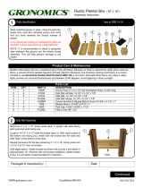
Parts Identifi cation Box 1
Stack matching pieces in piles.
Using the parts list, locate and
count the individual pieces and
verify that you have received the
correct number of pieces.
If any pieces are missing or
replacement parts are required,
contact Gronomics at 1-855-299-
6727.
NOTE: It is recommend to place
a protective layer between the
ground and the pieces during
assembly. This will help prevent
damage to the pieces.
Parts List Box 1 of 2
ITEM QTY. PART # DESCRIPTION
1 1 7003-Lt Three Sided Dovetail Corner Post (Left) 4” x 4” x 36”
2 1 7003-Rt Three Sided Dovetail Corner Post (Right) 4” x 4” x 36”
3 6 7009 Post w/13” Dovetail Depth 4” x 4” x 30”
4 1 7004-Rt Side Rail w/Double Cleat (Right) 21” x 5-1/2” x 1”
5 1 7004-Lt Side Rail w/Double Cleat (Left) 21” x 5-1/2” x 1”
6 2 7005 Side Rail w/Cleat 21” x 5-1/2” x 1”
7 4 7007 Side Rail 21” x 5-1/2” x 1”
8 2 1450 Side Rail 14-1/2” x 5-1/2” x 1”
9 4 1451 Narrow Center Side Rail 14-1/2” x 2-1/2” x 1”
10 2 1551 Corner Notched Bottom Board 15-1/2” x 4-1/2” x 1”
11 4 1550 Bottom Board 15-1/2” x 5-1/2” x 1”
12 8 3100 Post Cap 4-1/2” x 4-1/2” x 1-1/2”
13 2 2002 Fabric Liner 22” x 36”
1
2
EPB 24-82
EPB 24-82S
4
5
6
7
8
9
12
12
10
10
11
11
13
13
3
Packaged & Inspected by: Date:

www.gronomics.com East Bethel, MN USA 763-753-7374
Continued
2
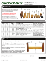
Parts Identifi cation Box 2
Using the parts list, locate and count
the individual pieces and verify that
you have received the correct number
of pieces.
If any pieces are missing or
replacement parts are required,
contact Gronomics at 1-855-299-
6727.
NOTE: It is recommend when to place
a protective layer between the ground
and the pieces during assembly
.
This will help prevent damage to the
pieces.
Parts List Box 2 of 2
ITEM QTY. PART # DESCRIPTION
14 1 7110 Planter Bench (pre-assembled)
15 2 4501
16 1 4501L
8 6 1450
17 4 7006
10 2 1551
18 6
R410-318ZY
Side Rail 45 x 5-1/2” x 1”
Side Rail w/ Logo 45 x 5-1/2” x 1”
Side Rail 14-1/2” x 5-1/2” x 1”
Narrow Center Side Rail 21” x 2-1/2” x 1”
Corner Notched Bottom Board 15-1/2” x 4-1/2” x 1”
10 x 3-1/8 R4 GRK Multi-Purpose Screw
14
14
15
15
16
16
10
10
18
18
8
17
17

www.gronomics.com East Bethel, MN USA 763-753-7374
Continued
Planter Bench Backrest Assembly
3
NOTE: The posts slots must be positioned as shown.
Lay the 4” x 4” x 36” three sided dovetail corner post
(left) (Item 1) on the ground (as shown).
Lay the 4” x 4” x 36” three sided dovetail corner post
(right) (Item 2) on the ground (as shown).
Locate a 45” x 5-1/2” side rail (Item 15). Install the
side rail into the curved dovetail slots and slide to the
bottom of the slots.
Planter Bench Backrest Assembly Continued
4
Install the remaining 45” x 5-1/2” side rail (Item 15)
into the slots and slide down.
Locate the 45” x 5-1/2” side rail w/Logo (Item 16).
Install the side rail (Logo facing down) into the slots
and slide to the bottom of the slots.
1
2
15
15
16
16
15
15
Curved
Dovetail
Slot
Curved
Dovetail
Slot
Slots Slots

www.gronomics.com East Bethel, MN USA 763-753-7374
Continued
Planter Bench / Planter Box Assembly
5
Stand the backrest assembly up (as shown). The
backrest should be slanted out at the top
Locate a 4” x 4” x 30” post (Item 3). Stand the post up
with slot facing out and slot facing the backrest assembly.
Install the 21” x 5-1/2” side rail w/double cleat (left)
(Item 5) (cleats located at the bottom) into the slots
on the posts and slide down to the bottom of the slots.
Short Cleat Located
(as shown)
Planter Bench / Planter Box Assembly Continued
6
Locate a 4” x 4” x 30” post (Item 3). Stand the post
up with slot facing out and slot facing the backrest
assembly.
Install the 21” x 5-1/2” side rail w/double cleat (right)
(Item 4) (cleats located at the bottom) into the slots
on the posts and slide down to the bottom of the slots.
3
4
Long Cleat Located
(as shown)
3
5
4

www.gronomics.com East Bethel, MN USA 763-753-7374
Continued
Planter Box Assembly
7
Stand a 4” x 4” x 30” post (Item 3) up with slot facing the
36” post and slot facing you.
Install the 14-1/2” x 5-1/2” side rail (Item 8) into the slots on
the posts and slide down to the bottom of the slots.
8
Planter Box Assembly Continued
8
Stand a 4” x 4” x 30” post (Item 3) up with slots facing
each post.
Install the 14-1/2” x 5-1/2” side rail w/cleat (Item 6)
(cleat located at the bottom) into the slots on the posts
and slide down to the bottom of the slots.
Install the 14-1/2” x 5-1/2” side rail (Item 8) into the
slots on the posts and slide down to the bottom of the
slots.
3
3
8
6
Cleat

www.gronomics.com East Bethel, MN USA 763-753-7374
Continued
Planter Box Assembly Continued
Planter Box Assembly Continued
9
Install the 14-1/2” x 2-1/2” narrow center side rails (Item 9)
into the slots on the posts and slide down.
Install the 21” x 2-1/2” narrow center side rails (Item 17) into
the slots on the posts and slide down.
17
17
17
17
9
Planter Box Assembly Continued
Install the 14-1/2” x 5-1/2” side rails (Item 8) into the
slots on the posts and slide down.
Install the 21” x 5-1/2” side rails (Item 7) into the slots
on the posts and slide down.
7
10
10
7
8

www.gronomics.com East Bethel, MN USA 763-753-7374
Continued
Corner Notched Bottom Board Assembly
Place one 15-1/2” x 4-1/2” corner notched bottom
board (Item 10) on each end of the planter box.
11
11
Bottom Board and Fabric Installation
Place two 15” x 5-1/2” bottom boards (Item 11) into
the planter box. (Gap boards evenly to allow for water
drainage).
Repeat steps 7 - 12 for planter box on opposite end of
planter bench backrest.
Locate the two pieces of fabric liner. Place one piece
in the bottom of each planter box.
Soil Capacity: 4.1 Cubic Feet
12
12
10
10
11
11

www.gronomics.com East Bethel, MN USA 763-753-7374
Planter Bench Assembly 5
Place the planter bench (Item 14) onto the side rail
w/double cleats (as shown).
Install the GRK R4 screws (Item 18) into the pre-
drilled holes at each end of the planter bench and
tighten.
13
13
Post Cap Assembly
Remove the rubber cap from the post stud.
Align the hole of the 4” x 4” post cap (Item 12) with
stud and tighten until the cap makes contact with the
post.
NOTE: Do not overtighten.
Repeat procedure for all posts.
14
14
Rubber Cap
Stud
12
12
14
14
18
18
/


