Page is loading ...

ISTRUZIONI PER L’USO ....................................................................................................1
GEBRAUCHSANLEITUNG .................................................................................................7
MODE D’EMPLOI ..............................................................................................................13
INSTRUCTIONS FOR USE...............................................................................................19
TECHNICAL INFORMATION ............................................................................................25
MIDIVAC CONTROLLER DESCRIPTION .............................................................................................25
MIDIVAC CONTROLLER SPECIFICATION ..........................................................................................27
MIDIVAC CONTROLLER OUTLINE ......................................................................................................27
PUMP CONNECTION ............................................................................................................................28
REMOTE I/O CONNECTOR ..................................................................................................................28
USE ........................................................................................................................................................30
Setting Mode .....................................................................................................................................30
Operating Mode.................................................................................................................................30
PRESSURE VS CURRENT DIAGRAMS ...............................................................................................30
ACCESSORIES AND SPARE PARTS...................................................................................................30

INSTRUCTIONS FOR USE
19 87-900-080-01 (D)
GENERAL INFORMATION
This equipment should only be used by trained
professionals. The user should read this instruction
manual and any other additional information supplied
by Varian before operating the equipment.
Varian will not be responsible for an events caused by
non-compliance to operational procedures, non
authorised modifications of the equipment, or any
action not sanctioned by national standards.
Detailed information is supplied in the appendix
"Technical Information".
This manual uses the following standard protocol:
!
The warning messages are for attracting the attention
of the operator to a particular procedure or practice
which, if not followed correctly, could lead to serious
injury.
CAUTION!
The caution messages are displayed before
procedures which, if not followed, could cause damage
to the equipment.
NOTE
The notes contain important information taken from the
text.
CONTROLLER DESCRIPTION
Varian’s MidiVac controller is a ion pump controller.
The unit can be factory configured according to the
customer’s needs, or the user can order separately the
option cards relevant to the serial communication and
the Set Point function.
The controller can be configured with two connectors in
order to power two ion pumps. In this case the
displayed current values are the sum of the currents
relevant to the two pumps.
The base versions of the MidiVac are detailed in the
following table (the polarity of the voltage is not user
configurable):
DESCRIPTION P/N
Base unit with 120 Vac
power supply and
negative polarity
929-5000
(single
connector)
929-5004
(double
connector)
Base unit with 120 Vac
power supply and positive
polarity
929-5001
(single
connector)
929-5005
(double
connector)
Base unit with 230 Vac
power supply and
negative polarity
929-5002
(single
connector)
929-5006
(double
connector)
Base unit with 230 Vac
power supply and positive
polarity
929-5003
(single
connector)
929-5007
(double
connector)
STORAGE
When transporting and storing the controllers, the
following environmental requirements should not be
exceeded:
• Temperature: from -20 °C to +70 °C
• Relative humidity: 0 to 95% (without condensing)
WARNING!

INSTRUCTIONS FOR USE
20 87-900-080-01 (D)
PREPARATION FOR INSTALLATION
The controller is supplied in a special protective
packing. If this shows signs of damage which may have
occurred during transport, contact your local sales
office.
When unpacking the controller, be sure not to drop it
and avoid any kind of sudden impact or shock
vibration.
Do not dispose of the packing materials in an
unauthorized manner. The material is 100% recyclable
and complies with EEC Directive 85/399.
INSTALLATION
!
The controller is equipped with a 3-wire power cord and
plug (internationally approved) for user’s safety. Use
this power cord and plug in conjunction with a properly
grounded power socket to avoid electrical shock.
Verify that the ground connections are properly
connected.High voltage developed in the controller can
cause severe injury or death. Before servicing the unit,
disconnect the power cable.
CAUTION!
The controller can be used as a bench unit or as a rack
module, but it must be positioned so that free air can
flow through the holes of the top and the side cover.
If the controller is used as a rack module, it MUST be
inserted in a 4 unit height rack adapter chassis due to
the weight of the controller.
The MidiVac front panel is not designed to support the
unit weight. Do not install or use the controller in an
environment exposed to atmospheric agents (rain,
snow, ice), dust, aggressive gases, in explosive
environments, or those with a high fire risk.
NOTE
If the controller is used as a bench unit, extend the two
front legs. If the controller is installed on a rack, remove
the four feet and position it with at least 30 mm (1.2
inches) of clearance on top and bottom.
During operation, the following environmental
conditions must be met:
• temperature: from 0 °C to +45 °C
• relative humidity: 0 - 95% (non-condensing)
To connect the controller to the pump use the specific
cable not supplied.
NOTE
The MidiVac is supplied with an interlock cable
connected between the screw (4) and the cable input
(8) (see the rear panel figure): do not remove this cable
otherwise the high voltage cannot be switched on.
NOTE
Without the interlock connection between pins 13 and
14 of the remote I/O connector the controller cannot
operate. To remotely switch ON or OFF the HV, a
voltage free contact must be applied between pins 13
and 14.
To switch ON the HV, the pins must be short circuited
(with the HV ON/OFF switch on the front panel in ON
position).
See the appendix “Technical Information” for detailed
information about the above mentioned and the other
connectors, and about the optional cards installation.
WARNING!

INSTRUCTIONS FOR USE
21 87-900-080-01 (D)
USE
This paragraph describes the fundamental operating
procedures. Detailed information and operating
procedures that involve optional connections or options
are supplied in the paragraph “USE” of the appendix
“Technical Information”.
Make all vacuum manifold and electrical connections
and refer to the connected pump instruction manual
prior to operating the controller.
!
To avoid injury to personnel and damage to the
equipment, if the controller is laying on a table make
sure it is steady.
MidiVac Front Panel Controls and Indicators
The figure and the table of the following page illustrate
the MidiVac front panel controls and indicators with
relevant description and function.
NOTE
Some controls and indicators change their function and
meaning according to the position of HV ON OFF
switch. The table describes all function and meaning.
MidiVac Rear Panel
The MidiVac controller rear panel controls and
connections are shown in the following figure.
For detailed information about the connections see the
appendix “Technical Information”.
Controller Rear Panel
WARNING!
1) “Remote I/O” connector for remote control
2) Port available for “Set Point” connector (optional)
3) Port available for serial connector (optional)
4) Screw for interlock cable connection
5) Port available for second interlock cable input (optional)
6) Port available for second HV connector (optional)
7) HV connector
8) Interlock cable input
9) Interlock cable
10) Fuses
11) Mains plug
12) Mains switch

INSTRUCTIONS FOR USE
22 87-900-080-01 (D)
DESCRIPTION
REF. DESCRIPTION
with (12) set to OFF with (12) set to ON
1
Downwards arrow When pressed, it decreases the value of the
function selected by means of the (16) pushbutton.
When pressed it changes the maximum output
voltage from 7 kV to 5 kV and from 5 kV to 3 kV.
2
Upwards arrow When pressed, it increases the value of the
function selected by means of the (16) pushbutton.
When pressed it changes the maximum output
voltage from 3 kV to 5 kV and from 5 kV to 7 kV.
3
V Control disabled. When pressed the display (9) shows the value of the
output voltage to the pump.
4
I Control disabled. When pressed the display (9) shows the pump
absorbed current.
5
Set 2 When it lights up the display (9) shows the Set
Point 2 value when selected by means of the (16)
pushbutton.
When it lights up the current value has reached the
Set Point 2 value.
6
Set 1 When it lights up the display (9) shows the Set
Point 1 value when selected by means of the (16)
pushbutton.
When it lights up the current value has reached the
Set Point 1 value.
7
Amp When it lights up the display (9) shows the pump
absorbed current.
8
KV When it lights up the display (9) shows controller
output voltage.
9
Display It shows the voltage or current value selected by
means of the pushbutton (16).
It shows the controller output voltage, or the pump
absorbed current.
10
3Kv / 5Kv / 7Kv The LED on corresponds to the maximum controller
output voltage.
The LED on corresponds to the maximum controller
output voltage.
11
PROTECT When it lights up the “Protect” operating mode is
activated.
When it flashes the controller is in setting mode.
When it lights up the “Protect” operating mode is
activated.
12
HV ON/OFF It switches on the high voltage. It switched off the high voltage.
13
HV When it lights up the high voltage is present.
14
REMOTE When it lights up the MidiVac is controlled by an
host computer.
When it lights up the MidiVac is controlled by an host
computer.
15
START
PROT
When pressed it activates the “Protect” operating
mode.
LED (11) flashes during the setting operations.
When pressed it activates the “Protect” operating
mode.
16
MENU If the MidiVac is in “Remote” mode, when pressed
it switches the operating mode to “Local”.
If the MidiVac is in “Local” mode, when pressed it
allows to access to the setting functions.
If the MidiVac is in “Remote” mode, when pressed it
switches the operating mode to “Local”.
If the MidiVac is in “Local” mode, when pressed it
allows to switch to “Remote”.

INSTRUCTIONS FOR USE
23 87-900-080-01 (D)
USE PROCEDURE
Operating Modes
The MidiVac controller can be set to operate in front
panel mode (“Local” mode), or by host computer
(“Remote” mode).
If no optional serial card is installed in the controller,
the “Remote” mode is unavailable.
If the serial card is installed, the “Local” mode can be
forced by pressing the “Menu” push-button on the front
panel: the “REMOTE” LED will blink.
If the HV is on and the temporary “Local” mode is
activated, all the operations in the normal “Local” mode
can be executed (see the following table regarding
controls and indicators). “Remote” mode can be
restored by pressing the “Menu” push-button. The
“REMOTE” LED should indicate normal operation.
When the HV is OFF and the temporary “Local” mode
is activated, only the setting operations can be
accessed. At the end of the settings menu, the unit will
default to true “Local” mode. To restore the “Remote”
mode, switch the HV on and press the “Menu” push-
button.
If the controller is set to “Remote” mode and the HV is
on, the high voltage signal will depend on the last
command (on or off) from the host computer. The initial
condition from the factory is an off signal. To turn ON
the HV it is necessary to switch to “Local” mode by
pressing the “Menu” push-button and engaging the HV
or to send the appropriate signal from the host
computer.
If the controller is set to “Remote” mode and the HV is
off, the high voltage signal can only be switched on by
an appropriate serial command from the host
computer.
The MidiVac controller can operate in “Start” or
“Protect” modes.
In the “Start” mode, when the high voltage is switched
on, the controller feeds the pump with the required
current until a fault condition is detected.
In the “Protect” mode two different conditions are
possible:
1. When the High Voltage is switched on the current
value exceeds the set trip current: while the
controller feeds the pump with the required current
until its value falls under the set threshold value, at
this time the controller operates with a “real
Protect” mode and it switches off the High Voltage
when the current exceeds its set threshold value
and displays the “Err2” message.
2. When the controller is switched on the current
value is less than the threshold value: in this case,
after a settling time of about 30 seconds when the
current is not controlled, the controller switches off
when the current value exceeds the set threshold
value and displays the “Err2” message.
Switching On and Off
To switch on the controller, it is necessary set to I
position the mains switch of the rear panel (see the
above figure).
To switch on the high voltage it is necessary to set to
ON position the front panel switch (12).
When the high voltage is switched on, the front panel
LEDs (10) show the preset maximum voltage value.
To show on the display the output voltage you must
push the front panel pushbutton (3); to show the current
you must press the (4) pushbutton.
NOTE
The output voltage value can change according to the
current: see the paragraph “MidiVac controller
description” of appendix “Technical information”.
To switch off the high voltage set to OFF position the
front panel switch (12). To switch off the controller set
to 0 position the mains switch of the rear panel.
MAINTENANCE
The MidiVac controller does not require any
maintenance. Any work performed on the controller
must be carried out by authorized personnel. When a
fault has occurred it is possible to use the Varian repair
service. Replacement controllers are available on an
advance exchange basis through Varian.
!
To avoid injury to personnel and damage to the
equipment, if the controller is laying on a table make
sure it is steady.
Before carrying out any work on the controller,
disconnect it from the supply. If a controller is to be
disposed, do so in accordance with the specific
national standards.
DISPOSAL
Meaning of the "WEEE" logo found in labels
The following symbol is applied in accordance with the
EC WEEE (Waste Electrical and Electronic Equipment)
Directive.
This symbol (valid only in countries of the European
Community) indicates that the product it applies to
must NOT be disposed of together with ordinary
domestic or industrial waste but must be sent to a
differentiated waste collection system.
The end user is therefore invited to contact the supplier
of the device, whether the Parent Company or a
retailer, to initiate the collection and disposal process
after checking the contractual terms and conditions of
sale.
WARNING!

INSTRUCTIONS FOR USE
24 87-900-080-01 (D)
ERROR MESSAGES
For a certain type of failure, the controller will self-
diagnose the error and the messages described in the
following table are displayed.
When the internal F1 fuse is broken, the display shows
the message Vout=0.0 from a few seconds and the
shows the message “Err 3”.
NOTE
When the MidiVac cover is removed the internal
security microswitch is open and the supply to the
controller is interrupted: the controller and all its
indicators are switched off and no message is
displayed on the display
MESSAGE DESCRIPTION REPAIR ACTION
Err 1 A short circuit condition (message “SCr”) has
been detected for more than 3 minutes.
The pump pressure is too high.
Turn off the high voltage and check the HV
cable against short circuits.
Improve the pump roughing pressure.
Switch off and on again the high voltage.
Should the error still be present, call the Varian
offices.
Err 2 The controller has switched off the High
Voltage for the “Protect” intervention.
Select the “Start” operating mode.
Set to OFF position the HV (12) switch. If you
want to switch on the high voltage even when
the current is higher than the “Protect” level, set
to the ON position the HV (12) switch.
Err 3 Controller generic fault of the High Voltage
control circuitry.
Switch the controller off and on again. Should
the error still be present, call the Varian offices.
Err 5 The interlock cable is not installed. When an High Voltage cable with the interlock
cable is available, check that the pump
connector is correctly inserted.
When the above mentioned cable is not
available, check that the interlock cable
supplied with the controller is connected
between ground and the jack connector under
the High Voltage connector.
Switch off and on again the controller. Should
the error still be present, call the Varian offices.
SCr The high voltage output is short-circuited.
The pump pressure is too high.
This condition can be present for a maximum
of 3 minutes, then the controller switches off
the high voltage and the message “Err 1” is
displayed.
Switch off the controller and check the high
voltage output status and remove the short
circuit condition.
Improve the pump roughing pressure.
Switch off and on again the controller. Should
the error still be present, call the Varian offices.

TECHNICAL INFORMATION
25 87-900-080-01 (D)
MIDIVAC CONTROLLER DESCRIPTION
The MidiVac Controller base is available in eight
versions which differ in the factory set input voltage, the
polarity and the number of High Voltage output
connectors.
• Model 929-5000 set for 120 Vac negative polarity and
single HV output connector
• Model 929-5001 set for 120 Vac positive polarity and
single HV output connector
• Model 929-5002 set for 230 Vac negative polarity and
single HV output connector
• Model 929-5003 set for 230 Vac positive polarity and
single HV output connector
• Model 929-5004 set for 120 Vac negative polarity and
double HV output connector
• Model 929-5005 set for 120 Vac positive polarity and
double HV output connector
• Model 929-5006 set for 230 Vac negative polarity and
double HV output connector
• Model 929-5007 set for 230 Vac positive polarity and
double HV output connector
MidiVac Controller

TECHNICAL INFORMATION
26 87-900-080-01 (D)
It consist of various boards. The following figure shows
the minimum configuration.
MidiVac Controller Boards (Top view)
1. Dc power supply board: it contains the EMI filter.
The ac input voltage is rectified and the needed
DC output voltages are generated.
2. Microprocessor board (located on front panel: it is
based on a single chip microprocessor with a large
input/output capability. It manages commands
coming from the front panel keyboard and drives
the front panel display and the high voltage output.
3. Voltage multiplier board: it multiplies four times the
voltage from the transformer.
4. Display and front panel keyboard: it contains the
functional push buttons, the LEDs indicating active
operating mode and the LCD display.
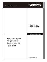
The high voltage circuitry receives the ac voltage from
the mains and converts it into an high voltage to drive
the pump. The output voltage and current are
continuously measured and displayed on the front
panel display. The controller automatically limits the
output voltage according to the following voltage versus
current diagram.
An analog signals output connector allows the user to
control the MidiVac operation (see the following
paragraph for more information about the signals
available on this connector).
NOTE
Leave at least 30 mm (1.2 inches) of free air circulation
on top and bottom of the unit for an efficient cooling of
the unit. Blind the unused slots on rear panel with the
provided covers.
10
-4
0
1000
2000
3000
4000
5000
6000
7000
V
o
l
t
a
g
e
(
V
)
10
-3
10
-2
Current (A)
10
-1
1

TECHNICAL INFORMATION
27 87-900-080-01 (D)
MIDIVAC CONTROLLER SPECIFICATION
Input:
− Voltage
(factory preset)
− Frequency
− Power
− Fuses
90 to 130 Vac - 1 phase
180 to 265 Vac - 1 phase
47 to 63 Hz
310 W
2 x 1.6 A external
1 x 1.6 A internal
(for 230 Vac models)
2 x 2.5 A external
1 x 2.5 A internal
(for 120 Vac models)
Output:
− Voltage
(selectable)
(polarity not
selectable)
− Current max
(short circuit)
− Power max
(3kV at 50mA)
Pos. Output
+ 7000 Vdc
(+2% -10%)
+ 5000 Vdc
(+/- 5%)
+ 3000 Vdc
(+/- 5%)
120 mA
150 W
Neg. Output
- 7000 Vdc
(+2% -10%)
- 5000 Vdc
(+/- 5%)
- 3000 Vdc
(+/- 5%)
120 mA
150 W
Operating:
− Temperature
− Humidity
0 to + 45 °C
90% maximum non
condensing
Recorder outputs
(analog signals)
(minimum recorder
impedance 1 MΩ)
− 0 to +5 Vdc logarithmic
corresponding to 1x10
-7
to 1x10
-1
A
− 0 to +0.1 Vdc
logarithmic
corresponding to 1x10
-7
to 1x10
-1
A
− 0 to +7 V linear
proportional to 0 to 7 kV
High Voltage output
Radio interference
suppression
Conforms to:
EN 61000-4.3
Safety requirements Conforms to:
EN 61010-1
Installation category II
Pollution degree 2
Cables Mains (2 m long, 3 wires)
Weight 6 Kg (13.2 lbs)
MIDIVAC CONTROLLER OUTLINE
The outline dimensions for the MidiVac Controller base unit are shown in the following figure.
MidiVac Controller Outline

TECHNICAL INFORMATION
28 87-900-080-01 (D)
PUMP CONNECTION
The pump is connected to the controller rear panel via
HV connector by a coaxial high voltage cable assembly
(cable to be separately ordered).
!
High voltage can cause severe injury or death.
When installing the high power cable:
− Turn the power off.
− Plug the cable on the pump side.
− Plug the cable on the controller side and secure it.
When removing the cable make sure that the power is
off.
The controller is able to accommodate cables which
contain an interlock circuit. Such an interlock will
disable the High Voltage if the cable is not connected
to the pump (or switch off if the High Voltage is already
on). This interlock cable must be connected to the
provided connector under the HV connector of the
MidiVac rear panel.
If there is no interlock circuit in the ion pump cable,
there is an interlock short attached to the MidiVac. The
cable is connected to the back of the rear chassis and
must be inserted into the corresponding jack.
Otherwise there will be an interlock fault on the control
unit.
REMOTE I/O CONNECTOR
The Remote I/O connector layout is shown in the
following figure.
Remote I/O Connector
The signals available on the connector pins are
detailed in the following table.
PIN DESCRIPTION
1 ON/OFF status (normally open)
2 ON/OFF status (normally closed)
3 Fault signal (normally open)
4 Fault signal (normally closed)
5 Start/Protect signal (normally open)
6 Start/Protect signal (normally closed)
7 Recorder output: 0 to +5 Vdc logarithmic
(see diagram)
8 Recorder output: 0 to +0.1 Vdc logarithmic
(see diagram)
9 Common of ON/OFF status signal
10 Common of fault signal
11 Common of Start/Protect signal
12 Recorder output: 0 to +7 Vdc linear
13 Interlock input/Remote HV ON/OFF
command
14 Ground
15 Ground
NOTE
Without the interlock connection between pins 13 and
14 of the remote I/O connector the controller cannot
operate. To remotely switch ON or OFF the HV, a
voltage free contact must be applied between pins 13
and 14.
To switch ON the HV, the pins must be short circuited
(with the HV ON/OFF switch on the front panel in ON
position).
WARNING!

TECHNICAL INFORMATION
29 87-900-080-01 (D)
Recorder Output Diagram from 0 to 5 V
Recorder Output Diagram from 0 to 0.1 V

TECHNICAL INFORMATION
30 87-900-080-01 (D)
USE
The controller can be used in two different modes:
• setting mode
• operating mode
The first mode enables the user to set some operating
parameters, the second one is the normal operating
condition.
Setting Mode
To access the setting mode the HV ON/OFF switch
must be set to the OFF position.
The parameters that can be set are accessed by
repeatedly pressing the “MENU” pushbutton of the front
panel. At this time the “START/PROT” pushbutton can
be pressed to select the “Protect” mode at the switching
ON.
1. The first selection of the “MENU” push-button to
sets the Set point 1 value. The display shows the
stored value and the flashing exponent can be
changed by the “Arrow” push-button. Pressing the
“I” pushbutton you can select another figure to be
modified. The default value is 1.0 x 10
-3
and the
setting value are from 0.0 x 10
-7
to 9.9 x 10
-2
. Note
that values equal to 0 are meaningless.
2. Pushing the “MENU” push-button a second time
shows the Set point 2 value. The display shows the
stored value and the flashing exponent can be
changed by the “Arrow” push-button. Pressing the
“I” pushbutton you can select another figure to be
modified. The default value is 1.0 x 10
-3
and the
setting value are from 0.0 x 10
-7
to 9.9 x 10
-2
. Note
that values equal to 0 are meaningless.
3. Pushing the “MENU” push-button a third time
shows the Protect value. The display shows the
stored value and the flashing figures can be
changed by the “Arrow” push-button. The only
figures that can be changed are the units and the
tens, while the exponent is fixed to 10
-2
. By
pressing the “I” pushbutton you can select the
figure to be modified.
The default value is 1.0 x 10
-2
.
4. Pushing the “MENU” push-button a fourth time
stores the set values.
NOTE
The “MENU” push-button must be always pressed until
the last step to store the new values.
The settings remain stored even when the controller is
switched off.
Operating Mode
During the normal operating condition the only available
operations are:
1. Switching on/off of the high voltage
2. Selection of the value (voltage or current) to be
displayed
3. Selection of the maximum output voltage value.
To switch on the high voltage the front panel switch HV
ON/OFF must be set in ON position.
When the high voltage is switched on the front panel
LEDs 3Kv/5Kv/7Kv show the preset maximum voltage
value.
To change the maximum output voltage value, press
the “Arrow” push-buttons in the front panel: the
“Upwards arrow” push-button increases the value, the
“Downwards arrow” push-button decreases it.
To display the output voltage, press the “V” push-button
in the front panel; to show the current the “I” push-
button must be pressed.
To switch off the high voltage the HV ON/OFF switch
must be set to OFF position.
PRESSURE VS CURRENT DIAGRAMS
In the following pages are shown the pressure vs
current diagrams of MidiVac for all VacIon pumps.
If two ion pumps are connected to the MidiVac, the
displayed current will be a sum of the two currents
drawn by the pumps.
ACCESSORIES AND SPARE PARTS
The MidiVac accessories and spare parts are detailed
in the following table.
DESCRIPTION P.N.
MD-RS232 serial communication
card
929-5010
MD-RS422 serial communication
card
929-5011
MD-RS485 serial communication
card
929-5012
MD-Set Point card 929-5020
Rack adapter 929-0064
HV bakeable cable, radiation
resistant, 4 m (13 ft.) long, with
interlock
929-0705
HV bakeable cable, radiation
resistant, 7 m (23 ft.) long, with
interlock
929-0707
HV bakeable cable, radiation
resistant, 10 m (33 ft.) long, with
interlock
929-0708
HV bakeable cable, radiation
resistant, 20 m (66 ft.) long, with
interlock
929-0709

Request for Return
1. A Return Authorization Number (RA#) WILL NOT be issued until this Request for Return is completely filled out,
signed and returned to Varian Customer Service.
2. Return shipments shall be made in compliance with local and international Shipping Regulations (IATA, DOT, UN).
3. The customer is expected to take the following actions to ensure the
Safety
of workers at Varian: (a) Drain any oils or
other liquids, (b) Purge or flush all gasses, (c) Wipe off any excess residues in or on the equipment, (d) Package the
equipment to prevent shipping damage, (for Advance Exchanges please use packing material from replacement unit).
4. Make sure the shipping documents clearly show the RA# and then return the package to the Varian location nearest you.
North and South America
Varian Vacuum Technologies
121 Hartwell Ave
Lexington, MA 02421
Phone : +1 781 8617200
Fax: +1 781 8609252
Europe and Middle East
Varian SpA
Via Flli Varian 54
10040 Leini (TO) – ITALY
Phone: +39 011 9979111
Fax: +39 011 9979330
Asia and ROW
Varian Vacuum Technologies
Local Office
CUSTOMER INFORMATION
Company name: ..………………….……..……………….………………………………..……………………...…………..….
Contact person: Name: ……………………………………..… Tel: ……………………….…...…………….….…....
Fax: …………………………….…...…..…… E-Mail: ..……………………..…………..…..…..…..
Ship Method: …………….……....…… Shipping Collect #: ………….…..………… P.O.#: ………………….…......………..
Europe only: VAT reg. Number: ………………..……………... USA only:
Taxable
Non-taxable
Customer Ship To: ………………………….……… Customer Bill To: …………………..……………...
……………..…………………... ..………………………………...
………………..………………... ..………………………………...
PRODUCT IDENTIFICATION
Product Description Varian P/N Varian S/N Purchase Reference
TYPE OF RETURN (check appropriate box)
Paid Exchange
Paid Repair
Warranty Exchange
Warranty Repair
Loaner Return
Credit
Shipping Error
Evaluation Return
Calibration
Other ……………….
HEALTH and SAFETY CERTIFICATION
Varian Vacuum Technologies CAN NOT ACCEPT any equipment which contains BIOLOGICAL HAZARDS or
RADIOACTIVITY. Call Varian Customer Service to discuss alternatives if this requirement presents a problem.
The equipment listed above (check one):
HAS NOT
been exposed to any toxic or hazardous materials
OR
HAS
been exposed to any toxic or hazardous materials. In case of this selection, check boxes for any materials that
equipment was exposed to, check all categories that apply:
Toxic Corrosive Reactive Flammable Explosive Biological Radioactive
List all toxic or hazardous materials. Include product name, chemical name and chemical symbol or formula.
.……………………………………………………………………………………………………………………..
Print Name: …………………………………. Customer Authorized Signature: ……………...…………………….
Print Title: …………………………………... Date: ..…../..…../……
NOTE:
If a product is received at Varian which is contaminated with a toxic or hazardous material that was not disclosed,
the customer
will be held responsible
for all costs incurred to ensure the safe handling of the product, and
is liable
for any harm or injury to Varian
employees as well as to any third party occurring as a result of exposure to toxic or hazardous materials present in the product.
Do not write below this line
Notification (RA)#: ……………………….……….. Customer ID#: ……….…………. Equipment #: ……………………..

Request for Return
FAILURE REPORT
TURBO PUMPS and TURBOCONTROLLERS
POSITION PARAMETERS
Does not start
Noise
Vertical
Power: Rotational Speed:
Does not spin freely
Vibrations
Horizontal
Current: Inlet Pressure:
Does not reach full speed
Leak
Upside-down
Temp 1: Foreline Pressure:
Mechanical Contact
Overtemperature
Other: Temp 2: Purge flow:
Cooling defective …………………. OPERATION TIME:
TURBOCONTROLLER ERROR MESSAGE:
ION PUMPS/CONTROLLERS VALVES/COMPONENTS
Bad feedthrough
Poor vacuum
Main seal leak
Bellows leak
Vacuum leak
High voltage problem
Solenoid failure
Damaged flange
Error code on display
Other
Damaged sealing area
Other
Customer application:
Customer application:
LEAK DETECTORS INSTRUMENTS
Cannot calibrate
No zero/high backround
Gauge tube not working
Display problem
Vacuum system unstable
Cannot reach test mode
Communication failure
Degas not working
Failed to start
Other
Error code on display
Other
Customer application:
Customer application:
PRIMARY PUMPS DIFFUSION PUMPS
Pump doesn’t start
Noisy pump (describe)
Heater failure
Electrical problem
Doesn’t reach vacuum
Over temperature
Doesn’t reach vacuum
Cooling coil damage
Pump seized
Other
Vacuum leak
Other
Customer application:
Customer application:
FAILURE DESCRIPTION
(Please describe in detail the nature of the malfunction to assist us in performing failure analysis):
NOTA: Su richiesta questo documento è disponibile anche in Tedesco, Italiano e Francese.
REMARQUE : Sur demande ce document est également disponible en allemand, italien et français.
HINWEIS: Auf Aufrage ist diese Unterlage auch auf Deutsch, Italienisch und Französisch erhältlich.

Sales and Service Offices
France and Benelux
Varian s.a.
7 Avenue des Tropiques
Z.A. de Courtaboeuf - B.P. 12
Les Ulis cedex (Orsay) 91941
France
Tel: (33) 1 69 86 38 84
Fax: (33) 1 69 86 29 88
From Benelux Tel: (31) 118 67 15 70
From Benelux Fax: (31) 118 67 15 69
Canada
Central coordination through:
Varian Vacuum Technologies
121 Hartwell Avenue
Lexington, MA 02421
USA
Tel: (781) 861 7200
Fax: (781) 860 5437
Toll Free # 1 (800) 882 7426
China
Varian Technologies - Beijing
Rm 1648 Central Tower South Wing
Beijing Junefield Plaza
No. 10 XuanWuMenWai Street
Beijing 100052
P.R. China
Tel: (86) 10 63108550
Fax: (86) 10 63100141
Toll Free: 800 820 6556
Germany and Austria
Varian Deutschland GmbH
Alsfelder Strasse 6
Postfach 11 14 35
64289 Darmstadt
Germany
Tel: (49) 6151 703 353
Fax: (49) 6151 703 302
India
Varian India PVT LTD
101-108, 1st Floor
1010 Competent House
7, Nangal Raya Business Centre
New Delhi 110 046
India
Tel: (91) 11 28521171
Fax: (91) 11 28521173
Italy
Varian Inc.
Vacuum Technologies
Via F.lli Varian 54
10040 Leini, (Torino)
Italy
Tel: (39) 011 997 9 111
Fax: (39) 011 997 9 350
03/06
Japan
Varian Vacuum Technologies
Sumitomo Shibaura Building, 8th Floor
4-16-36 Shibaura
Minato-ku, Tokyo 108
Japan
Tel: (81) 3 5232 1253
Fax: (81) 3 5232 1263
Toll Free: 0120 655 040
Korea
Varian Technologies Korea, Ltd
Shinsa 2nd Bldg. 2F
966-5 Daechi-dong
Kangnam-gu, Seoul
Korea 135-280
Tel: (82) 2 3452 2452
Fax: (82) 2 3452 2451
Toll Free: 080 222 2452
Mexico
Varian, S. de R.L. de C.V.
Concepcion Beistegui No 109
Col Del Valle
C.P. 03100
Mexico, D.F.
Tel: (52) 5 523 9465
Fax: (52) 5 523 9472
Taiwan
Varian Technologies Asia Ltd.
14F-6, No.77, Hsin Tai Wu Rd., Sec. 1
Hsi chih, Taipei Hsien
Taiwan, R.O.C.
Tel: (886) 2 2698 9555
Fax: (886) 2 2698 9678
Toll Free: 0800 051342
UK and Ireland
Varian Ltd.
6 Mead Road
Oxford Industrial Park - Yarnton
Oxford OX5 1QU - England
Tel: (44) 1865 291570
Fax: (44) 1865 291571
United States
Varian Vacuum Technologies
121 Hartwell Avenue
Lexington, MA 02421
USA
Tel: (781) 861 7200
Fax: (781) 860 5437
Other Countries
Varian Inc.
Vacuum Technologies
Via F.lli Varian 54
10040 Leini, (Torino)
Italy
Tel: (39) 011 997 9 111
Fax: (39) 011 997 9 350
Customer Support & Service:
North America
Toll-Free: 1 800 882 7426
vtl.technical.support@varianinc.com
Europe
Tel: 00 800 234 234 00
vtt.technical.support@varianinc.com
China
Toll-Free: 800 820 8266
vtc.technical.support@varianinc.com
Japan
Toll-Free: 0120 655 040
vtj.technical.support@varianinc.com
Korea
Toll-Free: 080 222 2452
vtk.technical.support@varianinc.com
Taiwan
Toll-Free: 0 800 051 342
vtw.technical.support@varianinc.com
Worldwide Web Site, Catalog
and Order On-line:
www.varianinc.com
Representative in most countries
/