
Luftheizgeräte
Air heaters
Appareils de chauffage à air chaud
07/2004
Einbauanweisung
Installation instructions
Notice de montage
Air Top 3500
Air Top 5000
Handelsbezeichnungen / Trade names /
Désignations commerciales :
Air Top 3500 B (Benzin / petrol / essence)
Air Top 3500 D (Diesel)
Air Top 5000 B (Benzin / petrol / essence)
Air Top 5000 D (Diesel)

Air Top 3500 / Air Top 5000
II
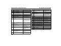
Inhaltsverzeichnis
1 Gesetzliche Bestimmungen für den Einbau ........................1
2 Verwendung und Ausführung ..............................................3
3 Einbau .....................................................................................4
4 Fabrikschild ............................................................................7
5 Einbaubeispiel .......................................................................8
6 Heizluftsystem .......................................................................9
7 Brennstoffversorgung .........................................................11
8 Brennluftversorgung ...........................................................16
9 Abgasleitung ........................................................................17
10 Brennluftansaug- und Abgasleitungen .............................18
11 Elektrische Anschlüsse ......................................................20
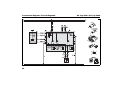
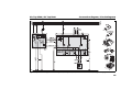
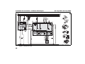
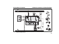
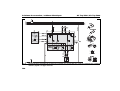
12 Anschlussschema / Schaltpläne ........................................23
13 Legende für Schaltpläne: ....................................................29
14 Erstinbetriebnahme .............................................................31
15 Störabschaltung ..................................................................32
16 Technische Daten ................................................................33
17 Ausführung ..........................................................................35
18 Bohrschablone .....................................................................36
Table of contents
1 Statutory regulations governing installation.................... 37
2 Use and version................................................................... 39
3 Installation............................................................................ 40
4 Factory plate........................................................................ 43
5 Installation example............................................................ 44
6 Hot air system...................................................................... 45
7 Fuel supply........................................................................... 47
8 Combustion air supply........................................................ 52
9 Exhaust pipe........................................................................ 53
10 Combustion air inlet and exhaust lines............................. 54
11 Electrical connections ........................................................ 56
12 Connection diagram/Circuit diagrams .............................. 59
13 Legend for circuit diagrams ............................................... 65
14 Starting the heater for the first time .................................. 67
15 Fault lock-out....................................................................... 68
16 Technical data...................................................................... 69
17 Version ................................................................................. 71
18 Drilling template .................................................................. 72
Page is loading ...

Air Top 3500 / Air Top 5000
IV
Page is loading ...
Page is loading ...
Page is loading ...
Page is loading ...
Page is loading ...
Page is loading ...
Page is loading ...
Page is loading ...
Page is loading ...
Page is loading ...
Page is loading ...
Page is loading ...
Page is loading ...
Page is loading ...
Page is loading ...
Page is loading ...
Page is loading ...
Page is loading ...
Page is loading ...
Page is loading ...
Page is loading ...
Page is loading ...
Page is loading ...
Page is loading ...
Page is loading ...
Page is loading ...
Page is loading ...
Page is loading ...
Page is loading ...
Page is loading ...
Page is loading ...
Page is loading ...
Page is loading ...
Page is loading ...
Page is loading ...
Page is loading ...

Air Top 3500 / Air Top 5000 Statutory regulations governing installation
37
1 Statutory regulations governing installation
The Air Top 3500 / Air Top 5000 heaters have been type-tested and
approved in accordance with EC Directives 72/245/EEC (EMC) and
2001/56/EC (heater) with the following EC permit numbers:
e1*72/245*95/54*1221*--
e1*2001/56*0015*--
e1*2001/56*0016*--
Installation is governed above all by the provisions in Annex VII of
Directive 2001/56/EC.
NOTE:
The provisions of these Directives are binding within the territory
governed by EU Directive 70/156/EEC and should similarly be
observed in countries without specific regulations.
(Extract from Directive 2001/56/EC Annex VII)
1.7.1. A clearly visible indicator within the user's field of vision must
show when the heater is switched on or off.
2. Regulations for installation in the vehicle
2.1. Scope
2.1.1. Subject to the provisions of paragraph 2.1.2, internal combustion
heaters must be installed in accordance with the requirements
contained in this Annex.
2.1.2. In the case of class O vehicles of class O (trailers) with heaters for
liquid fuel, it is presumed that these vehicles comply with the
requirements in this Annex.
2.2. Position of the heater
2.2.1. Parts of the vehicle body and other components in the immediate
vicinity of the heater must be protected against excessive heat and the
danger of contamination by fuel or oil.
2.2.2. The internal combustion heater must not pose a fire hazard even
when overheated. This requirement is deemed to have been met if care
is taken during installation to ensure an adequate distance from all parts,
as well as adequate ventilation and if fire-resistant materials or heat
shields are used.
2.2.3. For class M
2
and M
3
vehicles the heater must not be installed in
the passenger cabin. A device in a sealed cover, which also meets the
requirements set out in paragraph 2.2.2, may be used, however.
2.2.4. The plate mentioned in paragraph 1.4 (model plate) or a duplicate
thereof ( duplicate model plate ) must be fitted in such a way that it is still
clearly legible when the heater has been installed in the vehicle.
2.2.5. When positioning the heater, all reasonable precautions must be
taken to minimise the risk of personal injury or damage to items in the
vehicle.
2.3. Fuel supply
2.3.1. The fuel filler neck must not be located in the passenger
compartment and must have a tightly fitting cap to prevent any fuel
leaks.
2.3.2. The type of fuel and the fuel filler neck must be clearly identified
on heaters for liquid fuel, for which the fuel supply is separate from the
fuel supply for the vehicle.
2.3.3. A sign must be affixed to the fuel filler neck warning that the heater
must be switched off before refuelling. An identical warning must also be
included in the manufacturer's operating instructions.

Statutory regulations governing installation Air Top 3500 / Air Top 5000
38
2.4. Exhaust system
2.4.1. The exhaust outlet must be positioned in such a way that exhaust
fumes cannot get into the interior of the vehicle through ventilation
devices, hot-air inlets or open windows.
2.5. Combustion air inlet
2.5.1. The air for the combustion chamber of the heater must not be
extracted from the passenger cabin of the vehicle.
2.5.2. The air inlet must be positioned in such a way that it cannot be
obstructed by other objects.
2.6. Hot air inlet
2.6.1. The supply of heating air must consist of either fresh air or
recirculated air and must be taken from a clean area which cannot be
contaminated by exhaust fumes from the engine, the internal
combustion heater or any other source in the vehicle.
2.6.2. The inlet line must be protected by a grating or other suitable
means.
2.7. Hot air outlet
2.7.1. Hot air lines within the vehicle must be positioned or protected in
such a way as to exclude all risk of injury or damage caused by direct
contact.
2.7.2. The air outlet must be positioned or protected so that it cannot be
obstructed by other objects.
2.8. Automatic control of the heating system
When the engine stops, the heating system must cut out automatically
and the fuel supply must be stopped within 5 seconds.
The heating system may remain in operation if a manual unit has
already been activated.
IMPORTANT
Failure to follow the installation instructions and the notes contained
therein will lead to all liability being refused by Webasto The same
applies if repairs are carried out incorrectly or with the use of parts other
than genuine spare parts. This will result in the invalidation of the type
approval for the heater and therefore of its homologation / EC type
licence.

Air Top 3500 / Air Top 5000 Use and version
39
2 Use and version
2.1. Use of the air heaters
The Webasto Air Top 3500 and Air Top 5000 air heaters are designed
– to heat cabins, boats, trucks, minibuses, vans, ambulances and
motorhomes
– to defrost the vehicle windows
– to heat cargo
The heaters operate independently of the engine and are connected to
the fuel tank and the electrical system of the vehicle.
They may be used for vehicles with either water or air-cooled engines.
They are not designed for heating hazardous substances.

Installation Air Top 3500 / Air Top 5000
40
3 Installation
IMPORTANT
The statutory regulations governing installation on pages 1 and 2 must
be adhered to. The requirements of the latest version of the ADR must
also be observed for the installing the heater into vehicles used to
transport hazardous substances.
The heater must not be operated without the control unit cover (this will
cause the heater to overheat).
3.1. Air Top 3500 and Air Top 5000 installation situation
NOTE:
Check the installation situation of the relevant vehicle type.
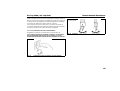
3.2. Installation location
The heater may be fitted either in the interior or on the exterior of the
vehicle.
If it is installed on the exterior ensure that the heater is fitted in a position
where it is protected from splashing water and spray.
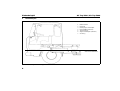
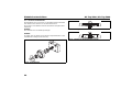
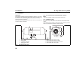
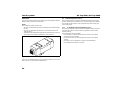
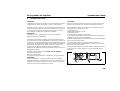
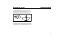
Fig. 1: Dimensions of the heater
1Hot air inlet
2 Hot air outlet
3 Combustion air intake
4 Exhaust fume outlet
5Fuel intake
6 Space requirement for hot air inlet
7 Space requirement for hot air outlet
8 Space requirement for removing the heater
9 Cable outlet (either right or left)

Air Top 3500 / Air Top 5000 Installation
41
The heater must be installed in such a way that no water can ingress into
it if the vehicle travels through a water hazard for which that vehicle is
licensed.
The openings for the combustion air inlet port, the exhaust outlet port
and the fuel pipe must be sealed splashing water if the heater is installed
in the interior. The seal designed and supplied for this purpose must be
used (see Figure 4).
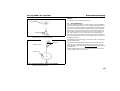
3.3. To install the heater
The M6 nuts must be tightened with a torque of 6 Nm +1 Nm for installing
the Air Top 3500 / Air Top 5000 heater.
The installation dimensions and space requirement for service access
are shown in the installation drawing (Figure 1). The specified horizontal
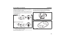
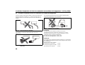
and axial angles must not be exceeded (Figure 2).
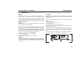
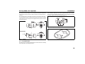
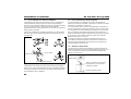
Fig. 2: Possible installation locations
Diesel heaters
Petrol heaters
0 - 90° 0 - 90° 0 - 90°
0 - 90° 0 - 90°
0 - 30°
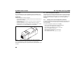
Fig. 3: Hole pattern
Fig. 4: Seal

Installation Air Top 3500 / Air Top 5000
42
A seal (Figure 4) must be fitted between the heater and the vehicle body.
This seal must be replaced each time the heater is installed.
The support area for the heater foot must be flat. A special tool can be
purchased from the manufacturer to drill the holes and, if necessary,
smooth the support area. The seal can compensate for unevenness of
max. 1 mm
.
IMPORTANT
After installation, check that the casing is not in contact with any parts of
the vehicle body. A failure to do this may result in the hot air fan blocking.
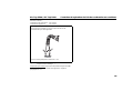
Fig. 5: Installation
Ensure that all moving parts can move easily!

Air Top 3500 / Air Top 5000 Factory plate
43
4 Factory plate
The model plate must be positioned so that it cannot be damaged and
must be clearly legible when the heater is installed (otherwise a
duplicate model plate must be used).
Inapplicable years must be erased from the model plate.

Installation example Air Top 3500 / Air Top 5000
44
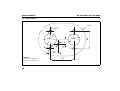
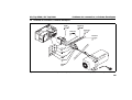
5 Installation example
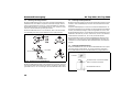
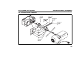
Fig. 6: Installation example for air heater in recirculation mode
1 Control element
2 Heater
3 Metering pump and damper
4 Fuel filter (accessory)
5 Tank connector
6 Exhaust silencer (accessory)
7Fuse
Maximum water passage height
1
2
3
5
4
7
6

Air Top 3500 / Air Top 5000 Hot air system
45
6 Hot air system
NOTE:
The heater must not be integrated into the vehicle’s air system. Both
recirculation and fresh air modes are possible.
For fresh air mode it must be ensured that the hot air is taken from an
area protected from splashing water and spray and in such a way that
no water can ingress into the heater if the vehicle travels through a water
hazard for which that vehicle is licensed.
NOTE:
For fresh air mode an external temperature sensor must be fitted in the
appropriate zone.
A temperature sensor is installed in the heater on the hot air intake side,
which operates the heater in the appropriate heat output range in
conjunction with the control element depending on the intake
temperatures and the position of the setpoint generator. The heat output
is set such that after the selected interior temperature has been reached
quickly, it is then kept at this selected value.
Minimum internal diameter of the hot air line:
90 mm for the Air Top 5000
80 mm for the Air Top 3500
75 mm may be used if approved by the manufacturer
NOTE:
Only materials that can withstand temperatures of at least 150°C may
be used for the hot air line. The hot air opening is to be positioned in
such a way that the air is not blown on to any parts that cannot withstand
the heat.
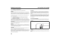
IMPORTANT
In vehicles used to convey passengers the air output opening is to be
positioned so that nobody can be located in front of the air output.
Maximum pressure drop between the inlet and outlet side of the hot air
line:
Air Top 3500 2.0 hPaAir Top 3500 Volume Plus 3.0 hPa
Air Top 5000 3.0 hPa
1 hPa corresponds to 1 mbar corresponds to 10 mm WC.
The test can also be carried out by measuring the temperature on the
actual heater:
Maximum temperature difference between hot air inlet and hot air outlet
130 K.
If this value is exceeded the temperature limiter will trip. The hot air hose
must be secured at its connection points.
If the heater is used in recirculation mode without a hot air guide, do not
short circuit the hot air flow.
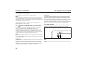
Fig. 7: Hot air inlet and hot air outlet

Hot air system Air Top 3500 / Air Top 5000
46
IMPORTANT
If you use the heater without a hot air inlet hose, the inlet grille supplied
with the heater must be used at all times.
NOTE:
The installation must be checked for:
– Air short circuit between the vehicle’s heating system and the heater
air inlet
– Air short circuit between the heater’s air inlet and the heater’s air
outlet (Figure 7)
– Adequate hot air intake facility (take the air intake from the cool area
of the cabin, for example for installations under a bench)
If you use an installation box the air vent must be sealed in such a way
that no hot air can get into the installation box.
6.1. External temperature sensor
We recommend that you install an external temperature sensor if the
heater is installed in an installation box or in places with poor ventilation
(for example under benches). This will prevent the heater having very
short control times.
6.1.1. To install the external temperature sensor
The external temperature sensor must be installed at medium height in
the passenger cabin on vertical surfaces if possible in the area that
requires heating.
The temperature sensor must not
– be in the direct current of hot air (from the vehicle’s own heating
system or the hot air heater).
– by close to heat sources (for example the vehicle’s own heating
system).
– be placed in direct sunlight (for example on the dashboard).
– be installed behind curtains or the like.
Fig. 8: Hot air inlet with inlet grille

Air Top 3500 / Air Top 5000 Fuel supply
47
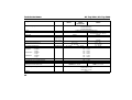
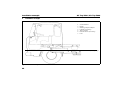
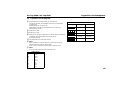
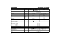
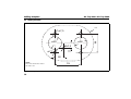
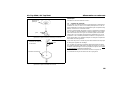
7 Fuel supply
The fuel is taken from the vehicle fuel tank or from a separate fuel tank.
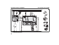
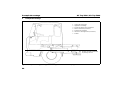
The values for the maximum pressure at the fuel extraction point are
shown in Figure 9.
Only for ADR:
The statutory regulation of ADR (Accord européen relatif
au transport international des marchandises dangereuses par route)
governing fuel tanks, part 9 para. 9.2.4.7 must be adhered to.
A sign must be affixed to the fuel filler neck warning that the heater must
be switched off before refuelling.
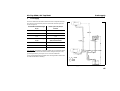
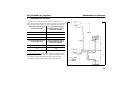
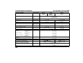
Permissible fuel inflow height
H (m)
At max. pressure (bar) in
fuel line
0.00 0.2
1.00 0.11
2.00 0.03
Maximum fuel intake height
S (m)
At max. negative pressure
(bar) in the fuel tank
0.00 -0.10
0.50 -0.06
1.00 -0.02
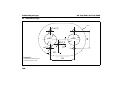
Fig. 9: Fuel supply
l
1
+ l
2
≤ 10 m
l
2
≤ 1.2 m
l
2
≤ 8.8 m
l
1
l
2
l
1
l
2

Fuel supply Air Top 3500 / Air Top 5000
48
7.1. Vehicles with carburettor engines
The fuel may only be extracted using the special Webasto fuel extractor
(see Figure 9) as close to the tank as possible. The connection may be
made in either the supply or return line, in which case the return line
must lead almost to the base of the tank. If this is not the case the return
line may be extended.
The fuel extractor must be fitted in such a way that any air or gas
bubbles are automatically discharged towards the tank (see Figure 10).
The fuel extractor should not be located near the engine, as gas bubbles
may form in the lines on account of heat radiated from the engine. This
may cause problems during combustion.
7.2. Vehicles with injection engines
When installing the heater in a vehicle with fuel injection system, it is
important to establish whether the fuel pump is located inside or outside
the tank.
If the fuel pump is located inside the tank, fuel can only be extracted from
the return line using the Webasto fuel extractor (see Figure 10), in which
case it must be ensured that the return line continues almost to the
bottom of the tank (see Figure 11 for details of the minimum distance
from the bottom of the tank). If this is not the case Webasto fuel extractor
(see Figure 11, 12 and 13) may be used.
If the fuel pump is installed outside the tank, the fuel connection may
also be made between the tank and the fuel pump, again using only the
Webasto fuel extractor (see Figure 10).
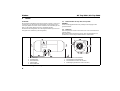
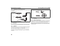
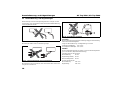
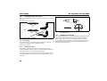
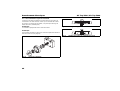
7.3. Vehicles with diesel engines
The fuel must be taken from the vehicle fuel tank or from a separate tank
(see Figs. 11, 12 and 13). This separate fuel pickup precludes any effect
of pressure.
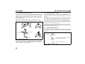
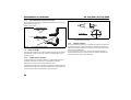
Fig. 10: Webasto fuel extractor
to metering pump
to engine
from tank
Fig. 11: Webasto tank connector
Hole pattern
Minimum distance 25 mm
Only use a tank connector if the fuel
tank is made from metal

Air Top 3500 / Air Top 5000 Fuel supply
49
NOTE:
The tank fitting must be made from metal!
7.4. Fuel lines
Only steel, copper and plastic lines of plasticised, light and temperature-
stabilized PA 11 or PA 12 (e.g. Mecanyl RWTL) pursuant to DIN 73378
may be used for the fuel lines.
Since the lines normally cannot be routed with a constant rising gradient,
the internal diameter must not be allowed to exceed a certain size. Air
or gas bubbles will accumulate in lines with an internal diameter of more
than 4 mm and these will cause malfunctions whilst the heater is
operating if the lines sag or are routed downwards. The diameters
specified in Figure 9 will ensure that bubbles do not form.
The lines should not be routed downwards from the metering pump to
the heater.
Unsupported fuel lines must be secured to prevent them sagging. They
must be installed in such a way that they cannot be damaged by flying
road chippings and high temperatures
(exhaust line).
The fuel lines must be secure at the connections using hose clips to
prevent their slipping.
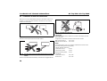
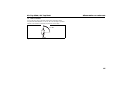
Fig. 12: Fuel pickup from the plastic tank
(Pickup via tank drain screw)
Fig. 13: Fuel pickup from the plastic tank
(Pickup via tank fitting)
Sealing ring
Plastic tank
Sealing ring
Tank connector
Tank fitting

Fuel supply Air Top 3500 / Air Top 5000
50
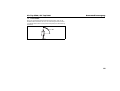
7.4.1. Connecting two pipes with a hose
The correct procedure for connecting fuel lines with hosing is shown in
Figure 14.
Ensure that there are no leaks!
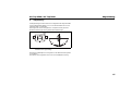
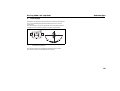
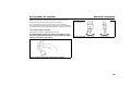
7.5. Dosing pump
The metering pump is a combined delivery, metering and shut-off
system and is subject to certain installation criteria
(see Figures 9 and 15).
7.5.1. Installation location
The metering pump must be installed in a cool place as close as
possible to the tank (see Figure 9). The maximum ambient temperature
must not exceed +20°C at any time during operation.
The metering pump and fuel lines must not be installed within range of
the radiated heat from hot vehicle parts. A heat shield must be used if
necessary.
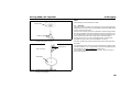
7.5.2. Installation and attachment
The metering pump must be secured with a vibration-damping mounting
(for example a rubberised clip). Its installation position is limited as
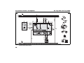
shown in Figure 15 in order to ensure effective automatic bleeding.
As a result of the risk of corrosion, only genuine Webasto parts may be
used for the plug connections between the metering pump and the
metering pump wiring harness.
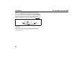
Fig. 14: Pipe / hose connection
Clip
Bubble
correct
wrong
Bubble
Fig. 15: Metering pump DP 30
Installation position
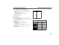
Air Top 3500 / Air Top 5000 D. 12 Volt und 24 Volt – diesel

Air Top 3500 / Air Top 5000 Fuel supply
51
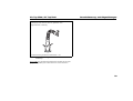
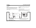
7.6. Fuel filter
Only a Webasto filter, order no. 487 171, is allowed to be used if the fuel
is expected to be contaminated. Install vertically if possible, however at
least horizontally (check flow direction).
Fig. 16: Fuel filter
0° - 90°

Combustion air supply Air Top 3500 / Air Top 5000
52
8 Combustion air supply
Under no circumstances may the combustion air be taken from areas
occupied by people. The combustion air intake opening must not point
in the direction of travel. It must be located so that it cannot become
clogged with dirt.
NOTE:
An intake silencer must be fitted if the intake line length is greater than
0.6 m.
NOTE:
The combustion air must be extracted using a combustion air line (if
necessary) from a position that is as cool as possible and protected from
splashing water.
Do not use an exhaust line as the combustion air line since otherwise
the metering pump cable from the combustion air inlet port may be
damaged.
The combustion air opening must not be under the minimum water
drive-through level permitted for the vehicle.
See the statutory regulations for the installation for further regulations.

Air Top 3500 / Air Top 5000 Exhaust pipe
53
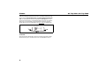
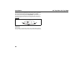
9 Exhaust pipe
Rigid pipes of unalloyed or alloyed steel with a minimum wall thickness
of 1.0 mm or flexible piping of alloyed steel only must be used as
exhaust line.
The exhaust pipe is secured to the heater using a clamping collar, for
example. See the statutory regulations for other requirements.
The exhaust silencer should ideally be installed near the heater.
The heater may also be operated without a silencer.
Fig. 17: Exhaust silencer
Flow direction (arbitrary)
Page is loading ...
Page is loading ...
Page is loading ...
Page is loading ...
Page is loading ...
Page is loading ...
Page is loading ...
Page is loading ...
Page is loading ...
Page is loading ...
Page is loading ...
Page is loading ...
Page is loading ...
Page is loading ...
Page is loading ...
Page is loading ...
Page is loading ...
Page is loading ...
Page is loading ...
Page is loading ...
Page is loading ...
Page is loading ...
Page is loading ...
Page is loading ...
Page is loading ...
Page is loading ...
Page is loading ...
Page is loading ...
Page is loading ...
Page is loading ...
Page is loading ...
Page is loading ...
Page is loading ...
Page is loading ...
Page is loading ...
Page is loading ...
Page is loading ...
Page is loading ...
Page is loading ...
Page is loading ...
Page is loading ...
Page is loading ...
Page is loading ...
Page is loading ...
Page is loading ...
Page is loading ...
Page is loading ...
Page is loading ...
Page is loading ...
Page is loading ...
Page is loading ...
Page is loading ...
Page is loading ...
Page is loading ...
Page is loading ...
-
 1
1
-
 2
2
-
 3
3
-
 4
4
-
 5
5
-
 6
6
-
 7
7
-
 8
8
-
 9
9
-
 10
10
-
 11
11
-
 12
12
-
 13
13
-
 14
14
-
 15
15
-
 16
16
-
 17
17
-
 18
18
-
 19
19
-
 20
20
-
 21
21
-
 22
22
-
 23
23
-
 24
24
-
 25
25
-
 26
26
-
 27
27
-
 28
28
-
 29
29
-
 30
30
-
 31
31
-
 32
32
-
 33
33
-
 34
34
-
 35
35
-
 36
36
-
 37
37
-
 38
38
-
 39
39
-
 40
40
-
 41
41
-
 42
42
-
 43
43
-
 44
44
-
 45
45
-
 46
46
-
 47
47
-
 48
48
-
 49
49
-
 50
50
-
 51
51
-
 52
52
-
 53
53
-
 54
54
-
 55
55
-
 56
56
-
 57
57
-
 58
58
-
 59
59
-
 60
60
-
 61
61
-
 62
62
-
 63
63
-
 64
64
-
 65
65
-
 66
66
-
 67
67
-
 68
68
-
 69
69
-
 70
70
-
 71
71
-
 72
72
-
 73
73
-
 74
74
-
 75
75
-
 76
76
-
 77
77
-
 78
78
-
 79
79
-
 80
80
-
 81
81
-
 82
82
-
 83
83
-
 84
84
-
 85
85
-
 86
86
-
 87
87
-
 88
88
-
 89
89
-
 90
90
-
 91
91
-
 92
92
-
 93
93
-
 94
94
-
 95
95
-
 96
96
-
 97
97
-
 98
98
-
 99
99
-
 100
100
-
 101
101
-
 102
102
-
 103
103
-
 104
104
-
 105
105
-
 106
106
-
 107
107
-
 108
108
-
 109
109
-
 110
110
-
 111
111
-
 112
112


Webasto Air Top 2000 S-B Installation Instructions Manual
- Type
- Installation Instructions Manual
- This manual is also suitable for
Ask a question and I''ll find the answer in the document
Finding information in a document is now easier with AI
in other languages
- français: Webasto Air Top 2000 S-B
- Deutsch: Webasto Air Top 2000 S-B
Related papers
-
Webasto AT 3500 ST / 5000 ST Operating instructions
-
Webasto AT 2000 STC Operating instructions
-
-
-
-
Webastoto Air Top 5000 ST Datasheet
-
Webasto Air Top 2000 ST B Technical data
-
-
-
Other documents
-
 MAXPEEDINGRODS MXR User manual
-
AUTOTERM PU-5 User manual
-
 Butler HL 90 Installation Instructions Manual
-
Fakir FW 500 Owner's manual
-
Trumatic S 5002 Installation Instructions Manual
-
Truma Ultraheat S 5004 Installation Instructions Manual
-
RIKA INTERNO Assembly Instructions Manual
-
Burley 537E-R Operating Instructions Manual
-
Volkswagen BA 6 1977 Insert For Instruction Manual
-

