Page is loading ...

INSTRUCTION MANUAL
TGA Series
Trace Gas Analyzers
Revision: 10/14
Copyright © 1992- 2014
Campbell Scientific, Inc.


Limited Warranty
“Products manufactured by CSI are warranted by CSI to be free from defects in
materials and workmanship under normal use and service for twelve months
from the date of shipment unless otherwise specified in the corresponding
product manual. (Product manuals are available for review online at
www.campbellsci.com.) Products not manufactured by CSI, but that are resold
by CSI, are warranted only to the limits extended by the original manufacturer.
Batteries, fine-wire thermocouples, desiccant, and other consumables have no
warranty. CSI’s obligation under this warranty is limited to repairing or
replacing (at CSI’s option) defective Products, which shall be the sole and
exclusive remedy under this warranty. The Customer assumes all costs of
removing, reinstalling, and shipping defective Products to CSI. CSI will return
such Products by surface carrier prepaid within the continental United States of
America. To all other locations, CSI will return such Products best way CIP
(port of entry) per Incoterms ® 2010. This warranty shall not apply to any
Products which have been subjected to modification, misuse, neglect, improper
service, accidents of nature, or shipping damage. This warranty is in lieu of all
other warranties, expressed or implied. The warranty for installation services
performed by CSI such as programming to customer specifications, electrical
connections to Products manufactured by CSI, and Product specific training, is
part of CSI's product warranty. CSI EXPRESSLY DISCLAIMS AND
EXCLUDES ANY IMPLIED WARRANTIES OF MERCHANTABILITY
OR FITNESS FOR A PARTICULAR PURPOSE. CSI hereby disclaims,
to the fullest extent allowed by applicable law, any and all warranties and
conditions with respect to the Products, whether express, implied or
statutory, other than those expressly provided herein.”

Assistance
Products may not be returned without prior authorization. The following
contact information is for US and international customers residing in countries
served by Campbell Scientific, Inc. directly. Affiliate companies handle
repairs for customers within their territories. Please visit
www.campbellsci.com to determine which Campbell Scientific company serves
your country.
To obtain a Returned Materials Authorization (RMA), contact CAMPBELL
SCIENTIFIC, INC., phone (435) 227-9000. After an application engineer
determines the nature of the problem, an RMA number will be issued. Please
write this number clearly on the outside of the shipping container. Campbell
Scientific’s shipping address is:
CAMPBELL SCIENTIFIC, INC.
RMA#_____
815 West 1800 North
Logan, Utah 84321-1784
For all returns, the customer must fill out a “Statement of Product Cleanliness
and Decontamination” form and comply with the requirements specified in it.
The form is available from our web site at www.campbellsci.com/repair. A
completed form must be either emailed to repair@campbellsci.com or faxed to
(435) 227-9106. Campbell Scientific is unable to process any returns until we
receive this form. If the form is not received within three days of product
receipt or is incomplete, the product will be returned to the customer at the
customer’s expense. Campbell Scientific reserves the right to refuse service on
products that were exposed to contaminants that may cause health or safety
concerns for our employees.

Precautions
DANGER — MANY HAZARDS ARE ASSOCIATED WITH INSTALLING, USING, MAINTAINING, AND WORKING ON OR AROUND
TRIPODS, TOWERS, AND ANY ATTACHMENTS TO TRIPODS AND TOWERS SUCH AS SENSORS, CROSSARMS, ENCLOSURES,
ANTENNAS, ETC. FAILURE TO PROPERLY AND COMPLETELY ASSEMBLE, INSTALL, OPERATE, USE, AND MAINTAIN TRIPODS,
TOWERS, AND ATTACHMENTS, AND FAILURE TO HEED WARNINGS, INCREASES THE RISK OF DEATH, ACCIDENT, SERIOUS
INJURY, PROPERTY DAMAGE, AND PRODUCT FAILURE. TAKE ALL REASONABLE PRECAUTIONS TO AVOID THESE HAZARDS.
CHECK WITH YOUR ORGANIZATION'S SAFETY COORDINATOR (OR POLICY) FOR PROCEDURES AND REQUIRED PROTECTIVE
EQUIPMENT PRIOR TO PERFORMING ANY WORK.
Use tripods, towers, and attachments to tripods and towers only for purposes for which they are designed. Do not exceed design
limits. Be familiar and comply with all instructions provided in product manuals. Manuals are available at www.campbellsci.com or
by telephoning (435) 227-9000 (USA). You are responsible for conformance with governing codes and regulations, including safety
regulations, and the integrity and location of structures or land to which towers, tripods, and any attachments are attached. Installation
sites should be evaluated and approved by a qualified engineer. If questions or concerns arise regarding installation, use, or
maintenance of tripods, towers, attachments, or electrical connections, consult with a licensed and qualified engineer or electrician.
General
• Prior to performing site or installation work, obtain required approvals and permits. Comply
with all governing structure-height regulations, such as those of the FAA in the USA.
• Use only qualified personnel for installation, use, and maintenance of tripods and towers, and
any attachments to tripods and towers. The use of licensed and qualified contractors is highly
recommended.
• Read all applicable instructions carefully and understand procedures thoroughly before
beginning work.
• Wear a hardhat and eye protection, and take other appropriate safety precautions while
working on or around tripods and towers.
• Do not climb tripods or towers at any time, and prohibit climbing by other persons. Take
reasonable precautions to secure tripod and tower sites from trespassers.
• Use only manufacturer recommended parts, materials, and tools.
Utility and Electrical
• You can be killed or sustain serious bodily injury if the tripod, tower, or attachments you are
installing, constructing, using, or maintaining, or a tool, stake, or anchor, come in contact with
overhead or underground utility lines.
• Maintain a distance of at least one-and-one-half times structure height, 20 feet, or the distance
required by applicable law, whichever is greater, between overhead utility lines and the
structure (tripod, tower, attachments, or tools).
• Prior to performing site or installation work, inform all utility companies and have all
underground utilities marked.
• Comply with all electrical codes. Electrical equipment and related grounding devices should
be installed by a licensed and qualified electrician.
Elevated Work and Weather
• Exercise extreme caution when performing elevated work.
• Use appropriate equipment and safety practices.
• During installation and maintenance, keep tower and tripod sites clear of un-trained or non-
essential personnel. Take precautions to prevent elevated tools and objects from dropping.
• Do not perform any work in inclement weather, including wind, rain, snow, lightning, etc.
Maintenance
• Periodically (at least yearly) check for wear and damage, including corrosion, stress cracks,
frayed cables, loose cable clamps, cable tightness, etc. and take necessary corrective actions.
• Periodically (at least yearly) check electrical ground connections.
WHILE EVERY ATTEMPT IS MADE TO EMBODY THE HIGHEST DEGREE OF SAFETY IN ALL CAMPBELL SCIENTIFIC PRODUCTS,
THE CUSTOMER ASSUMES ALL RISK FROM ANY INJURY RESULTING FROM IMPROPER INSTALLATION, USE, OR
MAINTENANCE OF TRIPODS, TOWERS, OR ATTACHMENTS TO TRIPODS AND TOWERS SUCH AS SENSORS, CROSSARMS,
ENCLOSURES, ANTENNAS, ETC.


Table of Contents
PDF viewers: These page numbers refer to the printed version of this document. Use the
PDF reader bookmarks tab for links to specific sections.
1. Introduction ................................................................. 1
2. Cautionary Statements ............................................... 2
3. Initial Inspection ......................................................... 3
4. Overview ...................................................................... 3
4.1 System Components ............................................................................. 6
4.1.1 Standard Components ................................................................... 7
4.1.1.1 TGA Power Module ........................................................... 7
4.1.1.2 TGA Accessory & Tool Kit ............................................... 8
4.1.1.3 TGA Test Intake ................................................................. 8
4.1.1.4 TGA Leak Check Nozzle ................................................... 8
4.1.1.5 TGA SDM Cable ................................................................ 9
4.1.1.6 Plastic Tubing ..................................................................... 9
4.1.1.7 CAT5 Ethernet Crossover Cable ........................................ 9
4.1.1.8 Serial Data Cable .............................................................. 10
4.1.1.9 TGA TEC Support Software and Operating System ........ 10
4.1.2 Optional Components ................................................................. 11
4.1.2.1 Laser ................................................................................. 11
4.1.2.2 AC Mains Power Cord ..................................................... 11
4.1.2.3 Power Module Mounting Brackets ................................... 12
4.1.3 Common Accessories.................................................................. 12
4.1.3.1 TGA Reference Gas Connection ...................................... 12
4.1.3.2 TGA Insulated Enclosure Cover ...................................... 13
4.1.4 Other Accessories ....................................................................... 14
4.1.4.1 TGA Air Sample Intake ................................................... 14
4.1.4.2 TGA Heated Intake Filter & Orifice ................................ 14
4.1.4.3 TGA High-Flow Filter Holder.......................................... 14
4.1.4.4 Sample Vacuum Pump ..................................................... 15
4.1.4.5 Bypass Vacuum Pump...................................................... 17
4.1.4.6 Sample Air Dryer ............................................................. 18
4.1.4.7 TGA Rotameter ................................................................ 21
4.1.5 Support Software ........................................................................ 22
4.1.6 Replacement Parts ....................................................................... 22
4.1.6.1 TGA Heated Intake Filter ................................................. 22
4.1.6.2 Filter Element ................................................................... 22
4.1.6.3 TGA Filter Elements, 47mm (Qty 100) ........................... 23
4.2 Theory of Operation ........................................................................... 23
4.2.1 Optical System ............................................................................ 23
4.2.2 Laser ........................................................................................... 25
4.2.3 Dewars ........................................................................................ 25
4.2.4 Detectors ..................................................................................... 25
4.2.5 Laser Scan Sequence................................................................... 26
4.2.6 Concentration Calculation .......................................................... 27
i

Table of Contents
5. Specifications ............................................................ 28
5.1 Measurement Specifications .............................................................. 28
5.2 Physical Specifications ...................................................................... 29
5.3 Power Requirements ......................................................................... 29
6. Installation ................................................................. 30
6.1 Analyzer Installation ......................................................................... 31
6.1.1 Plumbing Connections ............................................................... 33
6.1.2 Data Output Connections ........................................................... 35
6.1.3 Power ......................................................................................... 37
6.2 TGA Software Installation ................................................................ 39
6.2.1 Installation of PC Software ........................................................ 39
6.2.2 Updating TGA Operating System .............................................. 40
6.2.3 Configure Ethernet Connection .................................................. 42
6.2.4 Set TGA Serial Number and Identification String ..................... 45
6.2.5 Run the PC Software .................................................................. 46
6.3 Detailed Setup Instructions ............................................................... 46
7. Operation ................................................................... 46
7.1 Routine Operation ............................................................................. 46
7.1.1 Startup Procedure ....................................................................... 46
7.1.2 Routine System Checks .............................................................. 47
7.1.3 Shutdown Procedure .................................................................. 48
7.2 Software User Interface ..................................................................... 49
7.2.1 Connect Window ........................................................................ 49
7.2.2 Status Window ........................................................................... 51
7.2.3 Settings Window ........................................................................ 52
7.2.3.1 Laser ................................................................................ 53
7.2.3.2 Detectors .......................................................................... 59
7.2.3.3 Calculations ..................................................................... 61
7.2.3.4 Other ................................................................................ 66
7.2.4 Laser Window ............................................................................ 70
7.2.4.1 View Less/View More ..................................................... 71
7.2.4.2 Tabbed/Expand ................................................................ 72
7.2.4.3 Display Mode .................................................................. 73
7.2.4.4 Colors .............................................................................. 81
7.2.5 Find ............................................................................................ 81
7.2.6 Graph .......................................................................................... 84
7.2.7 Data ............................................................................................ 87
7.2.8 Files ............................................................................................ 88
7.3 Data Output ....................................................................................... 90
7.3.1 SDM Output ............................................................................... 90
7.3.1.1 Syntax .............................................................................. 91
7.3.1.2 Remarks ........................................................................... 91
7.3.2 TGA Output to PC ..................................................................... 94
7.3.3 TGA Analog Outputs ................................................................. 94
8. Troubleshooting and Maintenance .......................... 94
8.1 Lasers and Detectors ......................................................................... 94
8.2 Reference Gas ................................................................................... 95
8.3 Filtration and Sample Cell Cleaning ................................................. 95
8.4 Sample Pumps ................................................................................... 95
ii

Table of Contents
Appendices
A.
Configuring TGAs for Specific Gas Species ........ A-1
A.1 Laser Selection ................................................................................ A-1
A.1.1 LN
2
-cooled lasers ..................................................................... A-1
A.1.2 TE-cooled Lasers ..................................................................... A-1
A.1.3 Dewar Cables ........................................................................... A-2
A.1.4 Changing Lasers ...................................................................... A-2
A.2 Reference Gas ................................................................................. A-4
A.3 Detectors ......................................................................................... A-6
A.4 Finding the Absorption Line ........................................................... A-6
A.5 Air Gap Purge ................................................................................. A-7
B. Optical Alignment ................................................... B-1
B.1 Optical Alignment of TGA100 and TGA100A ................................ B-1
B.1.1 Initial Alignment ....................................................................... B-4
B.1.2 Horizontal and Vertical Alignment ........................................... B-5
B.1.3 Focus Adjustment ..................................................................... B-6
B.1.4 Reference Detector Coalignment .............................................. B-7
B.2 Optical Alignment of TGA200 and TGA200A ................................ B-7
B.2.1 Configure the TGA PC Software .............................................. B-9
B.2.2 Initial Alignment ....................................................................... B-9
B.2.3 Horizontal and Vertical Alignment ......................................... B-12
B.2.4 Focus Adjustment ................................................................... B-13
C. Optimizing Laser Parameters ................................ C-1
C.1 Laser Temperature ........................................................................... C-1
C.2 Zero Current ..................................................................................... C-5
C.3 High Current .................................................................................... C-7
C.3.1 High Current Count ................................................................ C-10
C.4 Omitted Data Count ....................................................................... C-11
C.5 Modulation Current ........................................................................ C-11
C.6 Laser Maximum Temperature and Laser Maximum Current ......... C-12
C.7 Laser Multimode Correction .......................................................... C-12
D. Optimizing Detector Parameters ........................... D-1
D.1 Detector Gain and Offset ................................................................ D-1
D.2 Detector Preamp Gain ..................................................................... D-1
D.3 Detector Temperature ..................................................................... D-1
D.4 Detector Linearity Coefficients ....................................................... D-2
E. Calibration ............................................................... E-1
F. TGA Frequency Response ..................................... F-1
F.1 Measurement Rate............................................................................ F-1
F.2 Sample Rate ..................................................................................... F-1
F.3 Digital Filters ................................................................................... F-2
F.4 Synchronicity ................................................................................... F-4
F.5 Sample Cell Residence Time ........................................................... F-5
iii

Table of Contents
G. Using Swagelok
®
Fittings ....................................... G-1
G.1 General Notes .................................................................................. G-1
G.2 Assembly ......................................................................................... G-1
G.3 Common Replacement Parts ........................................................... G-2
H. Upgrading Early Generation TGAs to TE-cooled
Laser H-1
H.1 TGA200 ........................................................................................... H-1
H.1.1 Basic Upgrade .......................................................................... H-1
H.1.2 Detectors .................................................................................. H-4
H.1.3 Power Module .......................................................................... H-4
H.1.4 Purge Boot ................................................................................ H-4
H.2 TGA100A ........................................................................................ H-4
H.2.1 Basic Upgrade .......................................................................... H-4
H.2.2 Detectors .................................................................................. H-5
H.2.3 Holes in Enclosure for Cryocooler Refrigerant Tubes ............. H-5
H.2.4 Temperature Control Upgrade ................................................. H-5
H.2.5 Power Module .......................................................................... H-6
H.2.6 Purge Boot ................................................................................ H-6
H.3 TGA100 ........................................................................................... H-6
H.3.1 Basic Upgrade .......................................................................... H-6
H.3.2 CPU Module ............................................................................ H-6
H.3.3 Input and Output Modules........................................................ H-6
H.3.4 Detectors and Detector Cables ................................................. H-7
H.3.5 Temperature Controller ............................................................ H-9
I. Install Temperature Control Upgrade ..................... I-1
I.1 Install Thermistor Probes .................................................................. I-1
I.2 Connect the Control Cable ................................................................ I-3
I.3 Enter Control Parameters .................................................................. I-4
I.4 Testing ............................................................................................... I-4
I.1 Operation ........................................................................................... I-5
Figures
4-1. Screen of TGA Windows software ...................................................... 5
4-2. TGA200A system components ........................................................... 7
4-3. TGA200A power module .................................................................... 8
4-4. TGA test intake ................................................................................... 8
4-5. TGA leak check nozzle ....................................................................... 9
4-6. TGA CAT5 Ethernet Crossover Cable .............................................. 10
4-7. Serial data cable ................................................................................ 10
4-8. TGA reference gas connection .......................................................... 13
4-9. TGA with insulated cover enclosure ................................................. 13
4-10. TGA air sample intake ...................................................................... 14
4-11. TGA heated intake filter and orifice .................................................. 14
4-12. TGA High-Flow Filter holder ........................................................... 15
4-13. RB0021 sample pump ....................................................................... 15
4-14. XDD1 sample pump .......................................................................... 16
4-15. DOAV502 vacuum pump .................................................................. 17
4-16. DAAV505 vacuum pump .................................................................. 18
4-17. PD1T air sample dryer ...................................................................... 20
4-18. PD1T-1.5 air sample dryer ................................................................ 20
iv

Table of Contents
4-19. PD200T air sample dryer ................................................................... 21
4-20. PD625 air sample dryer ...................................................................... 21
4-21. TGA rotameter ................................................................................... 22
4-22. TGA heated intake filter .................................................................... 22
4-23. TGA filter element replacement ......................................................... 23
4-24. 47 mm replacement filters .................................................................. 23
4-25. TGA100 and TGA100A optical configuration .................................. 24
4-26. TGA200 and TGA200A optical configuration .................................. 24
4-27. TGA laser scan sequence ................................................................... 26
6-1. Basic components required for TGA100 operation ........................... 30
6-2. Basic components required for TGA200 and TGA200A operation ... 31
6-3. TGA200A enclosure .......................................................................... 31
6-4. TGA100 and TGA100A transport locks ............................................ 32
6-5. TGA200 and TGA200A shipping clamps .......................................... 33
6-6. Feedthrough cover of TGA200A ....................................................... 33
6-7. Plumbing connections located under feedthrough cover of
TGA200A ....................................................................................... 34
6-8. SDM connections of TGA ................................................................. 35
6-9. SDM cable connector on TGA CPU board ........................................ 36
6-10. SDM cable tied to electronics box ..................................................... 36
6-11. DC power cable connected to TGA200A and secured on
electronics box ................................................................................ 37
6-12. Routing of SDM and power cable through TGA200A feedthrough
bracket ............................................................................................ 38
6-13. TGA200A power module with cables installed ................................. 39
6-14. PC shortcut icons for TGA Windows (left) and TGA TEC (right) .... 40
6-15. Serial cable connecting PC to RS232 port of TGA CPU module ...... 40
6-16. TGA100A/TGA200 OS download instruction................................... 41
6-17. Device configuration utility Logger Control tab ................................ 42
6-18. Device Configuration utility Settings Editor tab ................................ 43
6-19. Web-based decimal to hexadecimal converter ................................... 44
6-20. Device configuration utility Terminal tab .......................................... 45
7-1. TGA tool bar functions ...................................................................... 49
7-2. Connect window of TGA software interface ..................................... 50
7-3. TGA error message for incompatible serial numbers......................... 51
7-4. Toolbar before (top) and after (bottom) connection ........................... 51
7-5. TGA Status with a detected error (bottom) ........................................ 52
7-6. TGA Status window without error (left) and with error (right)
and line lock manually disabled. .................................................... 52
7-7. Expanded view of the menu in the TGA’s Settings window ............. 53
7-8. TGA Windows laser settings ............................................................. 54
7-9. TGA TEC laser settings ..................................................................... 54
7-10. Laser current parameter settings for TGA Windows ......................... 55
7-11. Laser current parameter settings for TGA TEC ................................. 56
7-12. Typical Line Lock parameter settings ................................................ 57
7-13. Settings of the Settings > Laser > Other screen ................................. 58
7-14. Ramp synchronization prompt ........................................................... 59
7-15. Controlling the detector temperature settings .................................... 60
7-16. PreAmp window default settings ....................................................... 61
7-17. Calculation concentrations settings .................................................... 62
7-18. Default settings for Channel 1 in analog input screen ........................ 63
7-19. Channel 2 settings for a TGA with thermistor probe ......................... 64
7-20. Typical pressure value inputs (values are specific to each TGA) ...... 65
7-21. Typical values for calculating δ13C on a TGA set with multiple
ramps .............................................................................................. 66
v

Table of Contents
7-22. TGA temperature control window for the two TGA enclosure
heaters ............................................................................................ 67
7-23. Data output setting window for SDM ............................................... 68
7-24. Setting a TGA serial number and identification string ...................... 69
7-25. About TGA window .......................................................................... 70
7-26. The TGA TEC screen for setting laser parameters ............................ 71
7-27. View Less/View More function of the Laser Settings window ......... 72
7-28. Tabbed/Expand function of the Laser Settings window .................... 73
7-29. Laser display modes .......................................................................... 74
7-30. Raw mode of laser display ................................................................ 75
7-31. Maximum View mode of laser display ............................................. 76
7-32. Magnified mode of laser display ....................................................... 77
7-33. Detrended mode of laser display ....................................................... 78
7-34. Folded mode of laser display ............................................................. 79
7-35. Absorbance mode of laser display ..................................................... 80
7-36. Setting options for laser window display .......................................... 81
7-37. Laser line find window ...................................................................... 82
7-38. Interactive Laser Find window for a CO2 isotope laser. ................... 83
7-39. Noninteractive Laser Find window ................................................... 84
7-40. Options for graphical display of data in TGA Windows ................... 85
7-41. Adding parameters to a graph in TGA TEC ...................................... 86
7-42. Example graph showing N2O concentration and standard
deviation ........................................................................................ 86
7-43. Data outputs of TGA TEC ................................................................. 88
7-44. Controlling PC recorded data options in the TGA ............................ 89
7-45. Example of log file messages ............................................................ 90
7-46. Setting TGA for SDM output from TGA Parameter Settings
Window .......................................................................................... 91
A-1. TGA100 or TGA100A optical layout with air gap purge ................ A-8
A-2. TGA200 or TGA200A optical layout with air gap purge ................ A-8
B-1. TGA100 and TGA100A optical layout ........................................... B-1
B-2. Alignment hardware of detector end of TGA100 and TGA100A ... B-2
B-3. Alignment hardware of laser end of TGA100 and TGA100A ........ B-3
B-4. TGA200 and TGA200A optical layout ........................................... B-8
B-5. Alignment hardware of laser end of TGA200 variants ................... B-8
B-6. Alignment hardware of detector end of TGA200 variants .............. B-9
B-7. Use of alignment tool for aligning mirror in TGA beamsplitter
block .......................................................................................... B-11
B-8. Use of alignment tool for aligning mirror in TGA beamsplitter
block, alternate angle ................................................................. B-11
B-9. Use of alignment tool to position tip/tilt screws for aligning
detector-side mirrors .................................................................. B-12
C-1. Typical laser DC current as a function of temperature .................... C-3
C-2. Typical reference transmittance as a function of laser
temperature .................................................................................. C-4
C-3. Typical concentration noise as a function of laser temperature ....... C-4
C-4. Typical sample detector signal as a function of laser temperature .. C-5
C-5. Example of using Laser Line Find function to determine laser
threshold current .......................................................................... C-6
C-6. Effects of temperature perturbation ................................................. C-7
C-7. High current adjustment procedure ................................................. C-8
C-8. Adjustment of omitted data counts ................................................ C-11
C-9. Adjustment of modulation current ................................................. C-12
F-1. EC filter coefficients ........................................................................ F-2
F-2. EC filter frequency response (linear scale) ....................................... F-3
F-3. EC filter frequency response (logarithmic scale) ............................. F-3
vi

Table of Contents
G-1. Swagelok® insert ............................................................................ G-3
G-2. Front and back Swagelok® ferrules ................................................ G-3
G-3. Swagelok® plug .............................................................................. G-4
G-4. Swagelok® cap ............................................................................... G-4
H-1. TE-cooled laser assembly installed in a TGA 200A ....................... H-1
H-2. TGA input module .......................................................................... H-2
H-3. TGA output module ........................................................................ H-2
H-4. Modules mounted into TGA200A electronics ................................ H-3
H-5. Cryocooler feedthrough holes with grommets (above) and plugs
(below) ......................................................................................... H-5
H-6. Older style TGA input module shipped with TGA100s .................. H-7
H-7. Older style TGA output module shipped with TGA100s ................ H-7
H-8. Older style two-piece detector holder and short cell ....................... H-8
H-9. Newer style combined detector holder/short cell (shown with
newer style cable) ........................................................................ H-9
I-1. Special control cable ......................................................................... I-1
I-2. Location of first thermistor probe attachment ................................... I-1
I-3. Location of second thermistor probe attachment .............................. I-2
I-4. Thermistor cable wiring to analog inputs .......................................... I-3
I-5. Control cable connection .................................................................. I-3
Tables
1-1. Historical Summary of Campbell Scientific Trace Gas Analyzers ...... 1
3-1. Parts Included with the TGA200A ....................................................... 3
4-1. Part Numbers for Available Gas Species Lasers ................................ 11
4-2. Available AC Mains Power Cords by Region ................................... 12
4-3. Power Module Mounting Brackets .................................................... 12
4-4. Sample Air Dryer Specifications ....................................................... 19
5-1. Typical Measurement Noise
a
............................................................. 29
5-2. Physical Specifications of TGA Variants ........................................... 29
7-1. Appearance and Function of Line Lock Icons ................................... 57
7-2. Suggested Naming for Gas Names Setting ........................................ 59
7-3. TGA Instruction ................................................................................. 92
7-4. Descriptions of TGAStatus Values .................................................... 94
A-1. Discontinued Cryogenic Lead-salt Lasers ....................................... A-1
A-2. TE-cooled Lasers ............................................................................ A-2
A-3. Replacement Cables for TGA Dewars ............................................ A-2
A-4. Suggested Reference Gas Concentrations ....................................... A-5
C-1. Example Laser Temperature Optimization Data .............................. C-2
F-1. Recommended Passband Settings .................................................... F-4
F-2. Processing Lags for EC filters .......................................................... F-5
F-3. Summary of TGA Update Times ..................................................... F-5
F-4. Sample Cell Residence Time as a Function of Sample Cell
Volume and TGA Model .............................................................. F-6
G-1. Available Plastic Tubing Sizes, Construction, and Usage
Guidelines .................................................................................... G-2
G-2. Dimensions and Part Numbers for Swagelok® Inserts ................... G-3
G-3. Dimensions and Part Numbers for Swagelok
®
Ferrules .................. G-3
G-4. Dimensions and Part Numbers for Swagelok
®
Plugs ...................... G-4
G-5. Dimensions and Part Numbers for Swagelok
®
Caps ....................... G-4
I-1. Control Parameters for TGA Thermistors .......................................... I-4
vii

Table of Contents
viii

TGA Series Trace Gas Analyzers
1. Introduction
Campbell Scientific has been manufacturing tunable diode laser absorption
spectrometer (TDLAS) trace gas analyzers (TGAs) since 1993. While the
TGAs have improved through a succession of four different generations, the
core technology remains the same. The TDLAS technique provides high
sensitivity, speed, and selectivity.
All Campbell Scientific TGAs are rugged, portable instruments designed for
use in the field. Common applications include gradient or eddy-covariance
flux measurements of methane or nitrous oxide, and isotope-ratio
measurements of carbon dioxide. Many of the important improvements are
available as upgrades for older models. These substantial upgrades blur the
lines between the various models. This manual covers all of the TGA models
to some extent, with emphasis on the later variants. A brief summary of these
TGA models and the most relevant improvements are summarized in TABLE
1-1.
TABLE 1-1. Historical Summary of Campbell Scientific Trace Gas Analyzers
TGA100 TGA100A TGA200 TGA200A
Ship dates
1993 – 2004 2005 – 2009 2008 – 2012 2014 –
CPU
Transputer
(upgradeable)
New New New
Software
Transputer DOS TGA Windows TGA TEC
Laser
Lead salt Lead salt Lead salt Interband
Cascade
Cooling options
LN
2
LN
2
or Cryocooler LN
2
Thermoelectric
Dewar capacity (L)
1.5 10.4 14.5 None
Optical
configuration
Beamsplitter at
detector end.
Beamsplitter at
detector end
Beamsplitter at
laser end. Long
sample and
reference cells.
Beamsplitter at
laser end
Absorption cells
Long sample
cell/short reference
cell
Long sample
cell/short reference
cell
Long sample and
reference cells
Long sample
and reference
cells.
Temperature
control
Fans only
(TGAHEAT optional
starting 2002)
TGAHEAT
included
Software Software
1

TGA Series Trace Gas Analyzers
Before proceeding, please study
• Section 2, Cautionary Statements
• Section 3, Initial Inspection
• Section 6, Installation
Operational instructions critical to preserving accurate measurements of the
system are found throughout this manual. Before proceeding, please study this
manual. Several other user manuals provide additional information and should
be consulted before using the TGA. These include:
• CR6 Measurement and Control Datalogger
• CR1000 Measurement and Control Datalogger
• CR3000 Micrologger
• CR5000 Measurement and Control System
all available at www.campbellsci.com
2. Cautionary Statements
• DANGER:
o All Campbell Scientific TGAs use Class 1M lasers. These lasers
are safe under all conditions of normal use except when passed
through magnifying optics such as microscopes and telescopes.
Do not view the laser directly with optical instruments.
o The power cords supplied with the TGA may not be of sufficient
length for a given site application. If longer AC power cords are
required, always have a qualified electrician perform the work.
• WARNING:
o Before attempting to install or change a laser in the TGA, read all
documentation accompanying the laser and thoroughly review
Appendix A.1.4, Changing Lasers, before attempting to change
or use a new laser. Laser settings and proper parameters must be
set according to the laser’s requirements and a defined order of
events must occur to initiate a new laser in the TGA. Failing to
do so could irretrievably damage the laser.
o The cam and bolt clamps of the TGA should be tightened during
transport. Failure to do so could damage the analyzer.
• CAUTION:
o The cam and bolt clamps of the TGA should only be tightened
during transport. They should always be loose during operation
of the TGA. The optical bench of the TGA should be free to
move within its enclosure with changes in temperature. Failure to
do so could result in inaccurate measurements.
2

TGA Series Trace Gas Analyzers
3. Initial Inspection
• Upon receipt of a Campbell Scientific TGA, inspect the packaging and
contents for damage. File damage claims with the shipping company.
Contact Campbell Scientific to facilitate repair or replacement.
• Immediately check package contents against shipping documentation.
Thoroughly check all packaging material for product that may be trapped
inside. Contact Campbell Scientific about any discrepancies. Model
numbers are found on each product. On cables, the model number is often
found at the connection end of the cable. Check that correct lengths of
cables are received.
• The TGA200A ships with the separate items listed in TABLE 3-1.
TABLE 3-1. Parts Included with the TGA200A
Part Number Description
15895 TGA Accessory & Tool Pack
15836 TGA Leak Check Nozzle, 25ft tubing
15838 TGA Test Intake, 5ft tubing
22178 TGA200A SDM Cable, 20ft
15702
Raw Plastic Tubing 1/4 in OD X .040 Wall
Polyethylene/Alum
18148 10Base-T CAT5 Ethernet Crossover Cable, 25ft
20730 9-Pin Female to 9-Pin Male Serial Data Cable, 25ft
30723 TGA TEC Support Software & OS
30981 TGA200A Power Module
4. Overview
The optical source of Campbell Scientific TGAs is a tunable diode laser that is
simultaneously temperature and current controlled to produce a linear
wavelength scan centered on a selected absorption line of the trace gas. A
beamsplitter allows most of the energy from the laser to pass through a 1.5 m
(4.9 ft) sample cell, where it is absorbed proportional to the concentration of
the target gas. The portion of the beam that is reflected by the beamsplitter
passes through a reference cell containing a prepared reference gas having a
known concentration of the target gas. The reference signal provides a
template for the spectral shape of the absorption line, allowing the
concentration to be derived independent of the temperature or pressure of the
sample gas or the spectral positions of the scan samples. The reference signal
also provides feedback for a digital control algorithm to maintain the center of
the spectral scan at the center of the absorption line. The simple optical design
avoids the alignment and contamination problems associated with multiple-
path absorption cells. The number of reflective surfaces is minimized to
reduce errors caused by Fabry-Perot interference.
3

TGA Series Trace Gas Analyzers
CPU
The TGA100 used a CPU module based on transputers. These CPU modules
had limited processing capability, so the TGA100 required a DOS PC (with
another transputer on an expansion card) to be connected in real time via a
fiber optic cable. The TGA100A used a new CPU module with sufficient
processing power to make the PC unnecessary. This transformed the TGA
from a PC-based system to a synchronous device for measurement (SDM)
sensor. Most of the TGA100s have been upgraded to this new CPU module.
Contact Campbell Scientific if you have questions regarding this upgrade.
Software
There have been four generations of TGA software. The TGA100 software
was distributed between three microprocessors: the transputer in the TGA100;
the transputer in the PC; and the PC itself. The PC provided the user interface
as well as storing data on the hard drive.
The TGA100A, which included the new CPU module, separated the TGA
firmware (operating system of the TGA itself) from the user interface software
which ran on the user’s PC. With this upgrade, the TGA became a stand-alone
sensor, and the PC became necessary only to check and adjust the operation of
the TGA. The second generation of the interface software ran only under DOS
PCs.
The third generation of user interface software, TGA Windows, was developed
for the TGA200. TGA Windows greatly improves the ease of use, and allows
the use of a modern PC running a Windows operating system. This software is
available as an upgrade for both the TGA100 (with CPU upgrade) and
TGA100A.
The fourth generation software, TGA TEC, is a minor update to the TGA
Windows software that is compatible with the thermoelectrically (TE) cooled
lasers used in the TGA200A. TGA Windows and TGA TEC are not mutually
compatible. TGA Windows is used only with LN
2
-cooled lasers and TGA TEC
is used only for TE-cooled lasers. A representative screen of the TGA
Windows software is shown in FIGURE 4-1.
4

TGA Series Trace Gas Analyzers
FIGURE 4-1. Screen of TGA Windows software
Laser
The lead-salt diode lasers used in the TGA100, TGA100A, and TGA200
required cryogenic cooling. These lasers were available at any wavelength
from 3 to 10 µm and could be specified to detect many different gases. Most
early TGAs used liquid nitrogen to cool the laser, but some TGA100As used a
closed-cycle refrigeration system (cryocooler). These lasers became
unavailable in 2012, when the only manufacturer discontinued production of
the laser. A new room-temperature thermoelectrically (TE) cooled interband
cascade laser (ICL) became available in 2014. This enabled the release of the
TGA200A. These ICLs are available as an upgrade for some of Campbell
Scientific’s older TGAs. See Appendix H, Upgrading Early Generation TGAs
to TE-cooled Laser, for details.
Dewars
The TGA100 was introduced with a small dewar (1.5 L) that required refilling
with LN
2
once or twice per day. A much larger (10.4 L) dewar was introduced
in 2002 with the evolution of the TGA100. The larger dewar allowed LN
2
filling only twice per week, rather than daily. Along with this new larger
dewar a cryocooler system was introduced as an alternative. The 10.4 L dewar
and the cryocooler were also used for the TGA100A.
The TGA200 used an even larger LN
2
dewar (14.5 L) to extend the refill
interval to once per week.
5

TGA Series Trace Gas Analyzers
The TE-cooled laser of the TGA200A operates without a LN
2
dewar.
Optical Configuration
The TGA100 and TGA100A have an optical assembly that includes a long
sample cell, a short reference cell, and a short sample cell. The beamsplitter of
the early TGAs was located at the back of the instrument, near the detectors.
TheTGA200 and TGA200A optical configuration has the beamsplitter at the
front (near the laser), with similar (long) sample and reference cells. The
optical alignment hardware and shipping clamps are also different.
Temperature Control
Early TGA100s had fans inside the enclosure to ensure all parts of the optical
system (in particular, the sample cell and the reference cell) remained at the
same temperature, but had no heater or temperature controller. An optional
accessory, the TGAHEAT, was introduced in 2002. TGAHEAT controlled
power to a pair of heaters attached to fans which maintained the temperature of
each end of the optical bench. For TGA100As, the TGAHEAT was included
as a standard component.
Temperature control was improved in the TGA200 and TGA200A by
controlling the temperature of the air at each end of the enclosure instead of the
optical bench and including temperature control in the TGA Windows
software. This allows the temperature setpoint to be changed through software
rather than opening the TGA enclosure to turn a potentiometer. It also allows
the user to monitor and record the fraction of power used for the heaters.
TGA100s with the TGAHEAT option and TGA100As that are running the
TGA Windows or TGA TEC software may be upgraded to control
temperatures through software. See Appendix I, Install Temperature Control
Upgrade, for installation details.
4.1 System Components
The TGA200A consists of several components, some of which must be
supplied by the user. Some additional accessories are required to complete a
fully functioning TGA200A system and are described and illustrated in the
sections that follow.
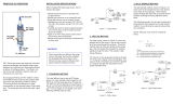
FIGURE 4-2 illustrates the main system components as well as additional
equipment needed to operate the TGA200A. The other TGA models are
similar.
6
/