Fluke 1577 User manual
- Category
- Measuring, testing & control
- Type
- User manual

®
1587/1577
Insulation Multimeters
Users Manual
PN 2401027
April 2005 Rev. 2, 6/09
© 2005-2009 Fluke Corporation. All rights reserved. Printed in USA. Specifications are subject to change without notice.
All product names are trademarks of their respective companies.

LIMITED WARRANTY AND LIMITATION OF LIABILITY
Each Fluke product is warranted to be free from defects in material and workmanship under normal use and service. The warranty period is three
years and begins on the date of shipment. Parts, product repairs, and services are warranted for 90 days. This warranty extends only to the original
buyer or end-user customer of a Fluke authorized reseller, and does not apply to fuses, disposable batteries, or to any product which, in Fluke's opin-
ion, has been misused, altered, neglected, contaminated, or damaged by accident or abnormal conditions of operation or handling. Fluke warrants
that software will operate substantially in accordance with its functional specifications for 90 days and that it has been properly recorded on non-
defective media. Fluke does not warrant that software will be error free or operate without interruption.
Fluke authorized resellers shall extend this warranty on new and unused products to end-user customers only but have no authority to extend a
greater or different warranty on behalf of Fluke. Warranty support is available only if product is purchased through a Fluke authorized sales outlet or
Buyer has paid the applicable international price. Fluke reserves the right to invoice Buyer for importation costs of repair/replacement parts when
product purchased in one country is submitted for repair in another country.
Fluke's warranty obligation is limited, at Fluke's option, to refund of the purchase price, free of charge repair, or replacement of a defective product
which is returned to a Fluke authorized service center within the warranty period.
To obtain warranty service, contact your nearest Fluke authorized service center to obtain return authorization information, then send the product to
that service center, with a description of the difficulty, postage and insurance prepaid (FOB Destination). Fluke assumes no risk for damage in transit.
Following warranty repair, the product will be returned to Buyer, transportation prepaid (FOB Destination). If Fluke determines that failure was caused
by neglect, misuse, contamination, alteration, accident, or abnormal condition of operation or handling, including overvoltage failures caused by use
outside the product’s specified rating, or normal wear and tear of mechanical components, Fluke will provide an estimate of repair costs and obtain
authorization before commencing the work. Following repair, the product will be returned to the Buyer transportation prepaid and the Buyer will be
billed for the repair and return transportation charges (FOB Shipping Point).
THIS WARRANTY IS BUYER'S SOLE AND EXCLUSIVE REMEDY AND IS IN LIEU OF ALL OTHER WARRANTIES, EXPRESS OR IMPLIED, IN-
CLUDING BUT NOT LIMITED TO ANY IMPLIED WARRANTY OF MERCHANTABILITY OR FITNESS FOR A PARTICULAR PURPOSE. FLUKE
SHALL NOT BE LIABLE FOR ANY SPECIAL, INDIRECT, INCIDENTAL OR CONSEQUENTIAL DAMAGES OR LOSSES, INCLUDING LOSS OF
DATA, ARISING FROM ANY CAUSE OR THEORY.
Since some countries or states do not allow limitation of the term of an implied warranty, or exclusion or limitation of incidental or consequential dam-
ages, the limitations and exclusions of this warranty may not apply to every buyer. If any provision of this Warranty is held invalid or unenforceable by
a court or other decision-maker of competent jurisdiction, such holding will not affect the validity or enforceability of any other provision.
Fluke Corporation
P.O. Box 9090
Everett, WA 98206-9090
U.S.A.
Fluke Europe B.V.
P.O. Box 1186
5602 BD Eindhoven
The Netherlands
11/99

i
Table of Contents
Title Page
Introduction .................................................................................................................... 1
Contacting Fluke ............................................................................................................ 1
Safety Information .......................................................................................................... 2
Accessories.................................................................................................................... 4
Unsafe Voltage............................................................................................................... 4
Test Lead Alert............................................................................................................... 4
Battery Saver (Sleep Mode) ........................................................................................... 4
Rotary Switch Positions.................................................................................................. 5
Buttons ........................................................................................................................... 6
Understanding the Display ............................................................................................. 8
Input Terminals............................................................................................................... 11
Power-Up Options.......................................................................................................... 12
AutoHold Mode............................................................................................................... 13
MIN MAX AVG Recording Mode .................................................................................... 13
Manual Ranging and Autoranging.................................................................................. 14
Understanding AC Zero Input Behavior of True RMS Meters ........................................ 15
Low-Pass Filter (Model 1587 and 1587T) ...................................................................... 15

1587/1577
Users Manual
ii
Making Basic Measurements......................................................................................... 16
Measuring AC and DC Voltage ................................................................................. 17
Measuring Temperature (Model 1587 and 1587T).................................................... 18
Measuring Resistance............................................................................................... 19
Measuring Capacitance (Model 1587 and 1587T) .................................................... 19
Testing for Continuity ................................................................................................ 20
Testing Diodes (Model 1587 and 1587T) .................................................................. 21
Measuring AC or DC Current .................................................................................... 22
Testing Insulation...................................................................................................... 24
Measuring Frequency (Model 1587 and 1587T) ....................................................... 25
Cleaning......................................................................................................................... 27
Testing the Batteries...................................................................................................... 27
Testing the Fuse ............................................................................................................ 27
Replacing the Batteries and Fuse.................................................................................. 28
Specifications................................................................................................................. 29
General Specifications .............................................................................................. 29
Electrical Specifications ................................................................................................. 30
AC Voltage Measurement ......................................................................................... 30
1587 and 1587T Accuracy ................................................................................... 30
1587 and 1587T Low-Pass Filter Voltage ............................................................ 31
1577 Accuracy...................................................................................................... 31
DC Voltage Measurement......................................................................................... 32
DC Millivolts Measurement ....................................................................................... 32
DC and AC Current Measurement ............................................................................ 33
Ohms Measurement.................................................................................................. 34
Diode Test (1587 and 1587T Only)........................................................................... 34
Continuity Test .......................................................................................................... 34
Frequency Measurement (1587 and 1587T Only) .................................................... 35

Contents
(continued)
iii
Frequency Counter Sensitivity................................................................................... 35
Capacitance (1587 and 1587T Only)......................................................................... 35
Temperature Measurement (1587 and 1587T Only) ................................................. 36
Insulation Specifications ............................................................................................ 36
Model 1587........................................................................................................... 37
Model 1577........................................................................................................... 37
Model 1587T......................................................................................................... 38

1587/1577
Users Manual
iv

v
List of Tables
Table Title Page
1. Symbols................................................................................................................................. 3
2. Rotary Switch Selections....................................................................................................... 5
3. Buttons .................................................................................................................................. 7
4. Display Indicators .................................................................................................................. 8
5. Error Messages ..................................................................................................................... 10
6. Input Terminal Descriptions................................................................................................... 12
7. Power-Up Options ................................................................................................................. 12

1587/1577
Users Manual
vi

vii
List of Figures
Figure Title Page
1. Rotary Switch ........................................................................................................................ 5
2. Buttons .................................................................................................................................. 6
3. Display Indicators .................................................................................................................. 8
4. Input Terminals...................................................................................................................... 11
5. Low Pass Filter...................................................................................................................... 15
6. Measuring AC and DC Voltage ............................................................................................. 17
7. Measuring Temperature ........................................................................................................ 18
8. Measuring Resistance........................................................................................................... 19
9. Measuring Capacitance......................................................................................................... 19
10. Testing for Continuity............................................................................................................. 20
11. Testing Diodes ...................................................................................................................... 21
12. Measuring AC or DC Current ................................................................................................ 23
13. Testing Insulation .................................................................................................................. 25
14. Measuring Frequency............................................................................................................ 26
15. Testing the Fuse.................................................................................................................... 27
16. Replacing the Fuse and Battery ............................................................................................ 28

1587/1577
Users Manual
viii

1
1587/1577
Insulation Multimeters
Introduction
The Fluke Models 1587,1587T, and 1577 are
battery-powered, true-RMS insulation multimeters
(hereafter "the Meter") with a 6000-count and a 3 ¾ digit
display. Although this manual describes the operation of
all models, all illustrations and examples assume use of
Model 1587.
These meters meet CAT III and CAT IV IEC 61010
standards. The IEC 61010 standard defines four
measurement categories (CAT I to IV) based on the
magnitude of danger from transient impulses. CAT III
meters are designed to protect against transients in Fixed
equipment installations at the distribution level; CAT IV
meters are designed to protect against transients from the
primary supply level (overhead or underground utility
service).
The Meter measures or tests the following:
• AC / DC voltage and
current
• Diodes (Model 1587)
• Resistance • Continuity
• Voltage and current
frequency
• Capacitance (Model
1587)
• Temperature (Model
1587)
• Insulation testing
Contacting Fluke
To contact Fluke, call one of the following telephone
numbers:
• Technical Support USA: 1-800-44-FLUKE (1-800-
443-5853)
• Calibration/Repair USA: 1-888-99-FLUKE (1-888-
993-5853)
• Canada: 1-800-36-FLUKE (1-800-363-5853)
• Europe: +31 402-675-200
• Japan: +81-3-3434-0181
• Singapore: +65-738-5655
• Anywhere in the world: +1-425-446-5500

1587/1577
Users Manual
2
Or, visit Fluke's website at www.fluke.com.
To register your product, visit http://register.fluke.com
.
To view, print, or download the latest manual supplement, visit http://us.fluke.com/usen/support/manuals
.
Safety Information
Use the Meter only as specified in this manual. Otherwise, the protection provided by the Meter may be impaired. See Table
1 for a list of symbols used on the Meter and in this manual.
A XWWarning identifies hazardous conditions and actions that could cause bodily harm or death.
A XWCaution identifies conditions and actions that could damage the Meter, the equipment under test, or cause
permanent loss of data.
XWWarning
To avoid possible electric shock or personal injury, follow these guidelines:
• Use the Meter only as specified in this manual or the protection provided by the Meter might be
impaired.
• Do not use the Meter or test leads if they appear damaged, or if the Meter is not operating properly. If in
doubt, have the Meter serviced.
• Always use the proper terminal, switch position, and range for measurements before connecting Meter
to circuit under test.
• Verify the Meter’s operation by measuring a known voltage.
• Do not apply more than the rated voltage as marked on the Meter, between the terminals or between
any terminal and earth ground.
• Use caution with voltages above 30 V ac rms, 42 V ac peak, or 60 V dc. These voltages pose a shock
hazard.

Insulation Multimeters
Safety Information
3
• Replace the battery as soon as the low battery indicator (b) appears.
• Disconnect circuit power and discharge all high-voltage capacitors before testing resistance,
continuity, diodes, or capacitance.
• Do not use the Meter around explosive gas or vapor.
• When using the test leads, keep your fingers behind the finger guards.
• Remove test leads from the Meter before opening the Meter case or battery door. Never operate the
Meter with the cover removed or the battery door open.
• Comply with local and national safety requirements when working in hazardous locations.
• Use proper protective equipment, as required by local or national authorities when working in
hazardous areas.
• Avoid working alone.
• Use only the replacement fuse specified or the protection may be impaired.
• Check the test leads for continuity before use. Do not use if the readings are high or noisy.
Table 1. Symbols
B AC (Alternating Current) J Earth Ground
F DC (Direct Current) I Fuse
X WARNING: risk of electric shock. T Double Insulated
b Battery (Low battery when shown on display.) W Important information; see manual
~ Do not dispose of this product as unsorted municipal waste. Go to Fluke’s website for recycling information.

1587/1577
Users Manual
4
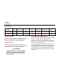
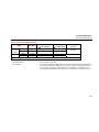
Accessories
Model
Leads
Probes
Clips
Holster
Hard Case
K Type
Thermocouple
Remote
Probe
1587 and 1587T TL224 TP74 AC285 Yes Yes Yes Yes
1577 TL224 TL74 AC285 Yes Yes No Yes
Unsafe Voltage
To alert you to the presence of a potentially hazardous
voltage, when the Meter detects a voltage ≥ 30 V or a
voltage overload (OL), the Z symbol is displayed.
Test Lead Alert
To remind you to check that the test leads are in the
correct terminals,
LEAd
is momentarily displayed when you
move the rotary switch to or from the c position.
XW Warning
To avoid a blown fuse, damage to the Meter,
or serious personal injury, never attempt to
make a measurement with a test lead in an
incorrect terminal.
Battery Saver (Sleep Mode)
The Meter enters the “Sleep mode” and blanks the display
if there is no function change or button press for
20 minutes. This is done to conserve battery power. The
Meter comes out of Sleep mode when a key is pressed or
when the rotary switched is turned.
To disable the Sleep mode, hold down the blue button
while turning the Meter on. Sleep mode is always disabled
in the MIN MAX AVG recording mode, AutoHold mode,
insulation test active, or if the auto power off feature has
been disabled by pressing the blue button when the Meter
is turned on.

Insulation Multimeters
Rotary Switch Positions
5
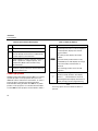
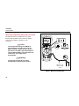
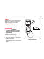
Rotary Switch Positions
Turn the Meter on by selecting any measurement function.
The Meter presents a standard display for that function
(range, measurement units, modifiers, etc.). Use the blue
button to select any rotary switch alternate functions
(labelled with blue letters). Rotary switch selections are
shown in Figure 1 and described in Table 2.
bav02f.eps
Figure 1. Rotary Switch
Table 2. Rotary Switch Selections
Switch
Position
Measurement Function
B
AC voltage from 30.0 mV to 1000 V.
K
(1587 and
1587T only)
AC voltage with 800 Hz “low-pass” filter.
C
DC voltage 1 mV to 1000 V.
E
DC mV 0.1 mV to 600 mV.
k
(1587 and
1587T only)
Temperature from - 40 °C to + 537 °C
(- 40 °F to + 998 °F).
Celsius is the default temperature
measurement unit. The temperature
measurement you select is retained in
memory when the Meter is turned off.
o
Ohms from 0.1 Ω to 50 MΩ.
N
(1587 and
1587T only)
Capacitance from 1 nF to 9999 μF.

1587/1577
Users Manual
6
Table 2. Rotary Switch Selections (cont.)
Switch
Position
Measurement Function
X
Continuity test. Beeper turns on at <25 Ω
and turns off at >100 Ω.
O
(1587 and
1587T only)
Diode test. There is no ranging in this
function. Displays
0L above 6.600 V.
c
AC mA from 3.00 mA to 400 mA (600 mA
overload for 2 minutes maximum).
DC mA from 0.01 mA to 400 mA (600 mA
overload for 2 minutes maximum).
a
INSULATION
Ohms from 0.01 MΩ to 2 GΩ.
Performs insulation test with 50, 100, 250,
500 (default), and 1000 V source on the
1587 or 500 (default) and 1000 V source
on the 1577 or 50 V (default) and 100 V on
the 1587T. The last selected high voltage
setting is retained in memory when the
Meter is turned off.
Press the blue button to activate smoothing
during insulation testing (1587 only).
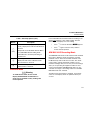
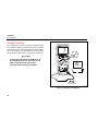
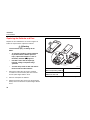
Buttons
Use the buttons to activate features that augment the
function selected with the rotary switch. The buttons are
shown in Figure 2 and described in Table 3.
bav03f.eps
Figure 2. Buttons

Insulation Multimeters
Buttons
7
Table 3. Buttons
Button Description
h
Press to freeze the displayed value. Press
again to release the display.
When a reading changes, the display
updates and the Meter beeps.
In MIN MAX AVG or Hz mode, this button
operates a display hold.
In Insulation Test mode, this schedules a
test lock the next time you press t on
the Meter or on the remote probe. The test
lock acts to hold down the button until your
press h or t again to release the
lock.
m
(1587 and
1587T
only)
Press to start retaining maximum, minimum,
and average values. Press successively to
display maximum, minimum, and average
values. Press and hold to cancel
MIN MAX AVG.
Button Description
f
(1587 and
1587T
only)
Activate frequency measurement.
r
Changes Ranging mode from Auto (default)
to Manual Ranging mode. Press and hold to
return to Auto Ranging mode.
H
Turns the backlight on and off. The backlight
goes off after 10 minutes.
t
Initiates an insulation test when the rotary
switch is on the
INSULATION position. Causes
the Meter to source (output) a high voltage
and measure insulation resistance.
G
The blue button. Functions as a shift key.
Press to access blue functions on the rotary
switch.

1587/1577
Users Manual
8
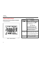
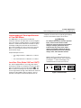
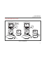
Understanding the Display
Display indicators are shown in Figure 3 and described in
Table 4. Error messages that may appear on the display
are described in Table 5.
bav01f.eps
Figure 3. Display Indicators
Table 4. Display Indicators
Indicator Description
b Low battery. Indicates when it is time
to replace the battery. When b is on,
the backlight button is disabled to
conserve battery life.
XW Warning
To avoid false readings, which
could lead to possible electric
shock or personal injury, replace
the battery as soon as the low
battery indicator appears.
L
LOCK
Indicates a test lock will be applied the
next time you press t on the
Meter or on the remote probe. The test
lock acts to hold down the button until
you press h or t again.
-
Q
Minus, or greater than symbols

Insulation Multimeters
Understanding the Display
9
Table 4. Display Indicators (cont.)
Indicator Description
Z Unsafe voltage warning. Indicates 30
V or greater (ac or dc depending on
the rotary switch position) is detected
on the input. Also appears when the
display shows 0L in the
B, C, or E
switch positions, and when batt
appears on the display. The Z also
appears when insulation test is active,
or in Hz.
a “Smoothing” enabled. Smoothing
dampens display fluctuations of rapidly
changing inputs by digital filtering.
Smoothing is available for insulation
testing on Model 1587 only. For more
on smoothing, see Power-Up options.
K
(1587 and
1587T only)
Indicates the low-pass filter function
for ac volts is selected.
Indicator Description
Y
S
Indicates AutoHold is active.
Indicates display hold is active.
M
n
(1587 and
1587T only)
Indicates minimum, maximum, or
average reading has been selected
using the m button.
X Continuity test function is selected
O
(1587 and
1587T only)
Diode test function is selected
nF, μF, ° C, ° F,
AC, DC, Hz, kHZ,
Ω, kΩ, MΩ, GΩ
Measurement units
0.0.0.0 Primary display
V
DC
Volts
1000 Secondary display

1587/1577
Users Manual
10
Table 4. Display Indicators (cont.)
Feature Description
Auto Range
ManualRange
610000mV
Display range in use
2500V
1000V
Source voltage rating for insulation
test: 50, 100, 250, 500 (default) or
1000 V on the 1587. 500 (default) and
1000 V ranges available on the 1577.
50 (default) and 100 V on the 1587T.
T Insulation test indicator. Appears when
insulation test voltage is present.
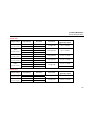
Table 5. Error Messages
Message Description
batt
Appears on the primary display and
indicates that the battery is too low for
reliable operation. The Meter will not
operate at all until the battery is replaced.
The b also appears when batt is on the
primary display.
bat
Appears on the secondary display and
indicates that the battery is too low to
perform an insulation test. The t
button is disabled until the battery is
replaced. This message disappears when
the rotary switch is turned to any other
function.
OPEn
Appears when an open thermocouple is
detected.
LEAd
Test lead alert. The message appears
briefly and a single beep will sound when
you move the switch in or out of the c
position.
15--Err
Model detect error. Service Meter if this is
displayed.
Page is loading ...
Page is loading ...
Page is loading ...
Page is loading ...
Page is loading ...
Page is loading ...
Page is loading ...
Page is loading ...
Page is loading ...
Page is loading ...
Page is loading ...
Page is loading ...
Page is loading ...
Page is loading ...
Page is loading ...
Page is loading ...
Page is loading ...
Page is loading ...
Page is loading ...
Page is loading ...
Page is loading ...
Page is loading ...
Page is loading ...
Page is loading ...
Page is loading ...
Page is loading ...
Page is loading ...
Page is loading ...
-
 1
1
-
 2
2
-
 3
3
-
 4
4
-
 5
5
-
 6
6
-
 7
7
-
 8
8
-
 9
9
-
 10
10
-
 11
11
-
 12
12
-
 13
13
-
 14
14
-
 15
15
-
 16
16
-
 17
17
-
 18
18
-
 19
19
-
 20
20
-
 21
21
-
 22
22
-
 23
23
-
 24
24
-
 25
25
-
 26
26
-
 27
27
-
 28
28
-
 29
29
-
 30
30
-
 31
31
-
 32
32
-
 33
33
-
 34
34
-
 35
35
-
 36
36
-
 37
37
-
 38
38
-
 39
39
-
 40
40
-
 41
41
-
 42
42
-
 43
43
-
 44
44
-
 45
45
-
 46
46
-
 47
47
-
 48
48


Fluke 1577 User manual
- Category
- Measuring, testing & control
- Type
- User manual
Ask a question and I''ll find the answer in the document
Finding information in a document is now easier with AI
Related papers
-
Fluke 1577 Insulation Multimeter User manual
-
Fluke 1577 Insulation Multimeter User manual
-
-
Fluke 77 User manual
-
-
-
-
Fluke 175 True-RMS Digital Multimeter User manual
-
-
Other documents
-
UEi Test Instruments DM384 User manual
-
Duracell 146E User manual
-
Mastech MS8360C User manual
-
UNI-T UT70D Operating instructions
-
UNI-T UT60E Specification
-
FLULKE Digital Multimeter User manual
-
 UEi DM400 User manual
-
Black Box FLUKE-179 Datasheet
-
 ennoLogic eM860T True RMS User manual
-
Elenco M2625A Owner's manual

