APsystems DS3 Series User manual

Type
User manual

APsystems DS3 Series microinverters are a reliable and efficient way to harness solar energy for your home or business. With advanced features like module-level monitoring, rapid shutdown compliance, and a sleek design, the DS3 Series provides a smart and powerful solution for your solar needs.

APsystems DS3 Series microinverters are a reliable and efficient way to harness solar energy for your home or business. With advanced features like module-level monitoring, rapid shutdown compliance, and a sleek design, the DS3 Series provides a smart and powerful solution for your solar needs.

Please scan this QR code to have
access to our APPs and Products
information
APsystems DS3 series
DS3-L and DS3 Microinverters
EMEA region
Installation Manual
ALTENERGY POWER SYSTEM Inc.
emea.APsystems.com
APsystems
Cypresbaan 7, 2908 LT, Capelle aan den Ijssel
The Netherlands
Tel: +31-10-2582670 EMAIL: info.emea@APsystems.com
Rue des Monts d’Or, ZAC de Folliouses Sud-Les Echets 01700 Miribel,
France
TEL: +33-481-65-60-40 EMAIL:info.emea@APsystems.com
© All Rights Reserved
APsystems DS3 series Installation/User Manual
Table of Contents
1.Important Safety Instructions ...................................................................................................... 2
1.1 Safety Instructions ...................................................................................................................................... 2
1.2 Radio Interference Statement .................................................................................................................... 3
1.3 Symbols replace words on the equipment, on a display, or in manuals ................................................... 4
2.APsystems Microinverter System Introduction............................................................................ 5
2.1 Key elements of an APsystems system ....................................................................................................... 5
2.2 The advantages of an APsystems system ................................................................................................... 6
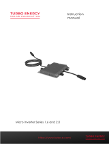
3.APsystems Microinverter DS3 series Introduction ....................................................................... 7
3.1 Characteristics of the DS3 microinverter .................................................................................................... 7
3.2 Features of the DS3 microinverter.............................................................................................................. 7
4.APsystems Microinverter System Installation.............................................................................. 8
4.1 Additional accessories supplied by APsystems .......................................................................................... 8
4.2 Other required accessories not supplied by APsystems ............................................................................ 8
4.3 Installation Procedures ............................................................................................................................... 9
4.3.1 Step 1 - Verify that grid voltage is matching with microinverter rating ......................................... 9
4.3.2 Step 2 Y3 AC Bus Cable distribution ............................................................................................. 9
4.3.3 Step 3 - Attach the APsystems Microinverters to the Racking ........................................................ 9
4.3.4 Step 4 - Ground the system ............................................................................................................ 10
4.3.5 Step 5 - Connect the APsystems microinverter to AC bus cable ................................................... 10
4.3.6 Step 6 - Install a Bus Cable End Cap at the end of AC bus cable ....................................................11
4.3.7 Step 7 - Connect APsystems Microinverters to the PV Modules .................................................. 12
4.3.8 Step 8 - Complete the APsystems installation map ...................................................................... 13
4.3.9 Step 9 - Warning Notice ................................................................................................................. 13
5. Microinverter system operating instructions ............................................................................ 14
6.Troubleshooting ......................................................................................................................... 15
6.1 Status Indications and Error Reporting .................................................................................................... 15
6.1.1 Start up LED .................................................................................................................................... 15
6.1.2 Operation LED ................................................................................................................................ 15
6.1.3 GFDI Error ....................................................................................................................................... 15
6.2 ECU_APP .................................................................................................................................................... 15
6.3 Installer EMA (web portal or EMA Manager APP) ................................................................................... 15
6.4 Trouble Shooting Guide ............................................................................................................................ 15
6.5 APsystems Technical Support ................................................................................................................... 16
6.6 Maintenance ............................................................................................................................................. 16
7.Replace a microinverter............................................................................................................. 17
8.Technical Data ............................................................................................................................ 18
8.1 DS3 series Microinverter Datasheet ......................................................................................................... 19
9. DS3 series - Wiring Diagram ..................................................................................................... 20
9.1 Sample Wiring Diagram - Single Phase ..................................................................................................... 20
10 APsystems Microinverter & Energy Communication Unit Installation Map ............................. 21
APsystems DS3 series Installation Manual
1.Important Safety Instructions
This manual contains important instructions to follow during installation and maintenance of the APsystems
Photovoltaic Grid-connected Microinverter. To reduce the risk of electrical shock and ensure a safe installation and
operation of the APsystems Microinverter, the following symbols appear throughout this document to indicate
dangerous conditions and important safety instructions.
Specifications are subject to change without notice. Please ensure you are using the most recent update found at
https://emea.apsystems.com/resources/library/
This indicates a situation where failure to follow instructions may cause a serious hardware failure or
personnel danger if not applied appropriately. Use extreme caution when performing this task.
This indicates information that is important for optimized microinverter operation. Follow these instructions
closely.
1.1 Safety Instructions
Only qualified professionals should install and/or replace APsystems Microinverters.
Perform all electrical installations in accordance with local electrical codes.
Before installing or using the APsystems Microinverter, please read all instructions and cautionary markings
in the technical documents and on the APsystems Microinverter system and the solar array.
Do NOT disconnect the PV module from the APsystems Microinverter without first disconnecting the AC
power.
Be aware that the body of the APsystems Microinverter is the heat sink and can reach a temperature of 80°C.
To reduce risk of burns, do not touch the body of the Microinverter.
Do NOT attempt to repair the APsystems Microinverter. If the micro is suspected to be faulty, please contact
your local APsystems Technical Support to start troubleshooting and obtain a RMA (Return Merchandise
Authorization) number to start the replacement process if needed. Damaging or opening the APsystems
Microinverter will void the warranty.
Caution!
When connecting a microinverter, it is recommended to first connect the AC Bus cable to the ground then
connect the AC connector to ensure proper earthing of the micro-inverter, then do the DC connections. When
disconnecting a microinverter disconnect the AC by opening the branch circuit breaker first but maintain the
protective earthing conductor in the branch circuit breaker connected to the microinverter, then disconnect
the DC inputs.
Please install AC breakers on the AC side of the inverter.
APsystems DS3 series Installation Manual
3
1.Important Safety Instructions
1.2 Radio Interference Statement
CE EMC ComplianceThe APsystems Microinverter can radiate radio frequency energy. If not installed and used
in accordance with the instructions, it may cause harmful interference to radio communication.
APsystems Microinverter complies with CE EMC regulations, which are designed to provide reasonable protection
against harmful interference in a residential installation.
Nonetheless, if the Microinverter does cause harmful interference to radio or television reception, you are
encouraged to try to correct the interferences by one of more of the following measures:
A) Reorient or relocate the receiving antenna
B) Increase the separation between the Microinverter and the receiver
C) Connect the Microinverter into an outlet on a circuit different from that to which the receiver is connected
If none of the recommendations suggested above bring significant improvement in terms of interferences, please
contact your local APsystems Technical Support.
APsystems DS3 series Installation Manual
4
1.Important Safety Instructions
1.3 Symbols replace words on the equipment, on a display, or in manuals
Trademark.
Caution, risk of electric shock.
Caution, hot surface.
Symbol for the marking of electrical and electronics devices according to Directive 2002/96/EC.
Indicates that the device, accessories and the packaging must not be disposed as unsorted
municipal waste and must be collected separately at the end of the usage. Please follow Local
Ordinances or Regulations for disposal or contact an authorized representative of the manufacturer
for information concerning the decommissioning of equipment.
CE mark is attached to the solar inverter to verify that the unit follows the provisions of the European
Low Voltage and EMC Directives.
Refer to the operating instructions.
Qualified personnel
Person adequately advised or supervised by an electrically skilled person to enable him or her to
perceive risks and to avoid hazards which electricity can create. For the purpose of the safety
information of this manual, a "qualified person" is someone who is familiar with requirements for
safety, electrical system and EMC and is authorized to energize, ground, and tag equipment,
systems, and circuits in accordance with established safety procedures. The inverter and complete
system may only be commissioned and operated by qualified personnel.
APsystems DS3 series Installation Manual
5
2.APsystems Microinverter System Introduction
2.1 Key elements of an APsystems system
The APsystems Microinverter is used in utility-interactive grid-tied applications, comprised of three key elements:
APsystems Microinverter
APsystems Energy Communication Unit (ECU)
APsystems Energy Monitor and Analysis (EMA) web-based monitoring and analysis system
Figure 1
PV
Module
Junction Box
YC600
Distributionbox
ECU
Internet EMA
APsystems DS3 series Installation Manual
6
2.APsystems Microinverter System Introduction
2.2 The advantages of an APsystems system
This integrated system maximizes solar energy harvest, improves safety, increases system reliability, and simplifies
solar system design, installation, maintenance, and management.
APsystems Microinverters maximize PV energy production
Each PV module has an individual Maximum Peak Power Tracking (MPPT) control, which ensures that the maximum
power is produced to the utility grid regardless of the performance of the other PV modules in the array. When PV
modules in the array are affected by shade, dust, different orientation, or any situation in which one module
underperforms compared to the other ones, the APsystems Microinverter ensures top performance from the array
by maximizing the performance of each module individually within the array.
Safety with APsystems Microinverters
In a typical string inverter installation, PV modules are connected in series. The voltage adds-up to reach high
voltage value (from 600 Vdc up to 1000 Vdc) at the end of the PV string. This extreme high DC voltage brings a
risk of electrical shocks or electrical arcs which could cause fire.
When using an APsystems microinverter, PV modules are connected in parallel. Voltage at the back of each PV
module never exceeds PV modules Voc, which is lower than 60 Vdc for most of PV modules used with APsystems
microinverters. This low voltage is considered “safe to touch” by firemen department and will avoid risk of
electrical shock, electrical arcs and fire hazards.
More reliable than centralized or string inverters
The distributed APsystems Microinverter system ensures that no single point of failure exists across the PV system.
APsystems Microinverters are designed to operate at full power at ambient outdoor temperatures of up to 65 deg
C (or 149 F). The inverter case is designed for outdoor installation and complies with the IP67 environmental
enclosure rating.
Simple to install
APsystems Microinverters are compatible with most of 60 and 72 cell PV modules or 120 and 144 half-cut cells PV
modules. (In order to confirm compatibility of PV module with APsystems microinverter, feel free to check our
online “E-decider” module compatibility tool or contact your local APsystems Technical Support).
Installation requires a minimum number of accessories and microinverters offer a lot of versatility to the installer:
microinverters can indeed be installed on different roofs with different orientation or with modules having
different orientation.
In the same way, end-user can extend their system whenever they want with microinverters.
Smart system performance monitoring and analysis
The APsystems Energy Communication Unit (ECU) is installed by simply plugging it into any wall outlet and
providing an Ethernet or Wi-Fi connection to a broadband router or modem. After installing and setting the ECU
(see ECU Instruction Manual), the full network of APsystems Microinverters automatically reports to the APsystems
Energy Monitor and Analysis (EMA) web server.
APsystems DS3 series Installation Manual
7
3.APsystems Microinverter DS3 series Introduction
3.1 Characteristics of the DS3 microinverter
APsystems 3rd generation of dual microinverters are reaching unprecedented power outputs of 730VA or 880VA to
adapt to today’s larger power module. With 2 independent MPPT, encrypted Zigbee signals, the DS3-L and DS3
benefit from an entirely new architecture and are fully backwards compatible with the QS1 and YC600
microinverters.
The innovative and compact design make the product lighter while maximizing power production. The components
are encapsulated with silicone to reduce stress on the electronics, facilitate thermal dissipation, enhance
waterproof properties, and ensure maximum reliability of the system via rigorous testing methods including
accelerated life testing. A 24/7 energy access through Apps or web based portal facilitate remote diagnosis and
maintenance.
The DS3 series is interactive with power grids through a feature referred to as RPC (Reactive Power Control) to
better manage photovoltaic power spikes in the grid. With a performance and an efficiency of 97%, a unique
integration with 20% less components, APsystems DS3-L and DS3 are a game changer to residential and commercial
PV.
3.2 Features of the DS3 microinverter
Key Product Features:
One microinverter connects to two PV modules
Maximum output power reaching 730VA (DS3-L) or 880VA (DS3)
Two input channels with independent MPPT
Reactive Power Control
Maximum reliability, IP67
Encrypted Zigbee communication
Safety protection relay integrated
Single phase microinverter. Possible to install in a balanced 3-phase system
APsystems DS3 series Installation Manual
8
4.APsystems Microinverter System Installation
A PV system using APsystems Microinverters is simple to install. Each Microinverter easily mounts on the PV racking,
directly beneath the PV module(s). Low voltage DC wires connect from the PV module directly to the Microinverter,
eliminating the risk of high DC voltage.
Installation MUST comply with local regulations and technical rules.
Special Statement: we advise to install a RCD breaker only if required by the local electrical code.
. Perform all electrical installations in accordance with local electrical codes.
. Be aware that only qualified professionals should install and/or replace APsystems Microinverters.
. Before installing or using an APsystems Microinverter, please read all instructions and warnings in the
technical documents and on the APsystems Microinverter system itself as well as on the PV array.
. Be aware that installation of this equipment includes the risk of electric shock.
. Do not touch any live parts in the system, including the PV array, when the system has been connected
to the electrical grid.
Even if not required by local electrical code, we strongly recommend to install surge protection devices in
the dedicated AC box.
4.1 Additional accessories supplied by APsystems
AC Y3 Bus cable
AC Y3 Bus Cable End Cap
AC Y3 Bus Cable Y-CONN Cap
AC Y3 Bus Cable Unlock Tool
ECU
AC connectors male/female
4.2 Other required accessories not supplied by APsystems
In addition to your PV array and its associated hardware, you may need the following items:
An AC connection junction box
Mounting hardware suitable for module racking
Sockets and wrenches for mounting hardware
APsystems Microinverter System Installation
APsystems DS3 series Installation Manual
9
APsystems Microinverter System Installation
4.3 Installation Procedures
4.3.1 Step 1 - Verify that grid voltage is matching with microinverter rating
4.3.2 Step 2 Y3 AC Bus Cable distribution
a. Each connector drop of the AC Bus cable shall be matching the position of the microinverter.
b. One end of the AC bus cable is used to access the junction box into the power grid.
c. Wire the conductors of the AC bus: L - BROWN ; N - BLUEPE - YELLOW GREEN.
Wiring color code can be different according to the local regulation. Check all the wires of the installation
before connecting to the AC bus to be sure they match. Wrong cabling can damage irreparably the
microinverters: such damage is not covered by the warranty.
It is strictly prohibited to hand carry the microinverter by its AC cable.
4.3.3 Step 3 - Attach the APsystems Microinverters to the Racking
a. Mark the location of the microinverter on the rack, with respect to the PV module junction box or any
other obstructions.
b. Mount one microinverter at each of these locations using hardware recommended by your module
racking vendor.
Figure 2
Install the microinverters (including DC and AC connectors) under the PV modules to avoid direct exposure
to rain, UV or other harmful weather events. Allow a minimum of 1.5 cm (3/4’’) below and above the casing
of the microinverter to allow proper air flow. The racking must be properly grounded as per local electrical
code.
APsystems DS3 series Installation Manual
10
APsystems Microinverter System Installation
4.3.4 Step 4 - Ground the system
Y3 AC Bus cable has an embedded PE wire: this might be sufficient to ensure proper grounding of the whole
PV array. However in areas with special grounding requirements, external grounding work may still be
needed, using the grounding lug supplied with the Microinverter
Figure 3
4.3.5 Step 5 - Connect the APsystems microinverter to AC bus cable
Insert the microinverter AC connector into the Y3 AC trunk cable connector. Make sure to hear the click” as a
proof of robust connection
Figure 4
Best Practice: Use the Bus Cable Unlock Tool of AC Bus to disconnect the connectors.
Figure 5
Please check the microinverter technical specifications (in Appendixes) to confirm the maximum number
of microinverters which can be connected on the same AC branch of the circuit.
Click
grounding lug
APsystems DS3 series Installation Manual
11
4.APsystems Microinverter System Installation
AC connector interface as shown below.
Figure 6
Cover any unused connectors with a Bus Cable Y-CONN cap to protect the unused connectors.
Figure 7
4.3.6 Step 6 - Install a Bus Cable End Cap at the end of AC bus cable
a. Strip cable jacket. c. Insert the wires into the cable clamps.
b. Insert the cable end into the seal. d. Rotate the nut with 3.3N·m until the
latching mechanism meets the base.
Figure 8
Nut
Seal
Body
APsystems DS3 series Installation Manual
12
4.APsystems Microinverter System Installation
4.3.7 Step 7 - Connect APsystems Microinverters to the PV Modules
Figure 9
When plugging in the DC cables, the microinverter should immediately blink red one time and green ten
times. This will happen as soon as the DC cables are plugged in and will show that the microinverter is
functioning correctly. This entire check function will start and end within 10 seconds of plugging in the unit,
so pay careful attention to these lights when connecting the DC cables.
Double check to make sure all of the AC and DC wiring has been correctly installed. Ensure that none of the
AC and/or DC wires are pinched or damaged. Make sure that all of the junction boxes are properly closed.
Each PV panel must be carefully connected to the same channel.
Make sure to not split positive and negative DC cables into two different input channels: microinverter will
be damaged and warranty will not apply.
APsystems DS3 series Installation Manual
13
4.APsystems Microinverter System Installation
4.3.8 Step 8 - Complete the APsystems installation map
a. Each APsystems Microinverter has 2 removable serial number labels.
b. Complete installation map by sticking ID label of each microinverter at the right location.
c. The second serial number label, could be stuck on the solar module frame, which could help later to
confirm the position of the microinverter without dismantling the PV module
Figure 10
①. The layout of the microinverters' serial numbers installation map is only suitable for typical installation
②. Installation Map is available in the last page appendix of this manual.
③. Use ECU_APP (available in the EMA Manager APP) to scan the serial numbers on the map when setting
up the ECU (see ECU instruction manual for more info).
4.3.9 Step 9 - Warning Notice
A warning notice must be placed in such a way that anyone with access to live parts is made aware of the need to
switch off these parts. It is imperative to verify that the power supply, measurement circuits (sense lines) and other
parts are not isolated from the network when the interface protection switch is open.
As a minimum, warning labels shall be placed:
On the switchboard (DNO panel and consumer unit) that has the PV generator connected to it;
On all switchboards in between the consumer unit and the PV generator itself;
On, or in the PV generator itself;
At all points of isolation for the PV generator
APsystems DS3 series Installation Manual
14
5. Microinverter system operating instructions
1. Turn ON the AC circuit breaker on each microinverter AC branch circuit.
2. Turn ON the main utility-grid AC circuit breaker. Your system will start producing power after approximately one
minute of waiting time.
3. Microinverter data will be available in the EMA Manager APP or in the EMA web portal.
Alternatively, LED sequences could be an indicator of microinverters status (see section 6.1)
Once the ECU has been commissioned properly, the APsystems Microinverters will start to send
performance data to the ECU. The time required for all of the Microinverters in the system to report to the
ECU will vary depending on the number of Microinverters in the system.
APsystems DS3 series Installation Manual
15
6.Troubleshooting
Qualified personnel can use the following troubleshooting steps if the PV system does not operate correctly:
6.1 Status Indications and Error Reporting
Assuming they are easily accessible and visible, Operation LEDs can give a good indication of the microinverters
status
6.1.1 Start up LED
One short red and ten short green blinks when DC power is first applied to the Microinverter indicates a
successful Microinverter startup.
6.1.2 Operation LED
Flashing Slow Green (5 sec. gap) - Producing power and communicating with ECU
Flashing Slow Red (5 sec. gap) - Not producing power
Flashing Fast Green (2 sec. gap) - Not communicating with ECU over 60mins, but still producing power.
Flashing Fast Red (2 sec. gap) - Not communicating with ECU over 60mins and not producing power.
Steady Red default, DC side ground fault protection, see 6.1.3
6.1.3 GFDI Error
A solid red LED indicates the Microinverter has detected a Ground Fault Detector Interrupter (GFDI) error in
the PV system. Unless the GFDI error has been cleared, the LED will remain red and the ECU will keep reporting
the fault. Please contact your local APsystems Technical Support.
6.2 ECU_APP
APsystems ECU_APP (available in the EMA Manager APP) is the recommended tool to do on-site troubleshooting.
When connecting the ECU_APP to the ECU hotspot (please check ECU User Manual for more detailed information),
installer can check every microinverter status (production, communication) but also Zigbee signal strength, grid
profile and other insightful data helping the troubleshooting.
6.3 Installer EMA (web portal or EMA Manager APP)
Before going on site for troubleshooting, installer can also check all information remotely using his installer account,
either on the web or using the EMA Manager APP (see EMA Manager APP User Manual for more detailed
information). Having access to module data (DC, AC, voltages and currents) gives the first indication on potential
issues.
6.4 Trouble Shooting Guide
Professional installers can also refer to our Troubleshooting Guide (www.apsystems.com, section libraries) to have
more in depth guideline on how to troubleshoot and fix PV installations powered by APsystems microinverters.
Or look at the frequently asked questions at https://emea.apsystems.com/resources/faq/
6
APsystems DS3 series Installation Manual
16
6.0 Troubleshooting
6.5 APsystems Technical Support
APsystems local Technical Support team is available to support professional installers to get familiar with our
products and to troubleshoot installations when needed.
Do not attempt to repair APsystems Microinverters. Please contact your local APsystems Technical Support.
①. Never disconnect the DC wire connectors under load. Ensure that no current is flowing in the DC wires
prior to disconnecting.
②. Always disconnect AC power before disconnecting the PV module wires from the APsystems
Microinverter.
③. The APsystems Microinverter is powered by PV module DC power. AFTER disconnecting the DC power,
when reconnecting the PV modules to the Microinverter, be sure to watch for the quick red light
followed by ten short green LED flashes.
6.6 Maintenance
APsystems microinverters do not require any specific regular maintenance.
APsystems DS3 series Installation Manual
17
7.Replace a microinverter
Follow the procedure to replace a failed APsystems Microinverter
A. Disconnect the APsystems Microinverter from the PV Module, in the order shown below:
1. Disconnect the AC by turning off the branch circuit breaker.
2. Disconnect the inverter AC connector from the AC Bus.
3. Disconnect the PV module DC wire connectors from the microinverter.
4. Remove the Microinverter from the PV array racking.
B. Install a replacement Microinverter to the rack. Remember to observe the flashing green LED light as soon as
the new Microinverter is plugged into the DC cables.
C. Connect the AC cable of the replacement Microinverter to the AC bus.
D. Close the branch circuit breaker and verify proper operation of the replacement Microinverter.
E. Update the micro inverter in EMA Manager APP or EMA portal through "Replace" function and update the
system's map with new serial number labels.
APsystems DS3 series Installation Manual
18
8.Technical Data
①. Be sure to verify that the voltage and current specifications of your PV module are compatible with the
range allowed on APsystems Microinverter. Please check the micro-inverter datasheet.
②. DC operating voltage range of the PV module must be within allowable input voltage range of the
APsystems Microinverter.
③. The maximum open circuit voltage of the PV module must not exceed the specified maximum input
voltage of the APsystems.
APsystems DS3 series Installation Manual
19
8.1 DS3 series Microinverter Datasheet
Model
DS3-L
DS3
Input Data (DC)
Recommended PV Module Power (STC) Range
255Wp-550Wp+
300Wp-660Wp+
Peak Power Tracking Voltage
25V-55V
32V-55V
Operating Voltage Range
16V-60V
26V-60V
Maximum Input Voltage
60V
Maximum Input Current
18A x 2
20A x 2
Output Data (AC)
Maximum Continuous Output Power
730VA
880VA
Nominal Output Voltage/Range*
230V/184-253V
Nominal Output Current
3.2A
3.8A
Nominal Output Frequency/ Range*
50Hz/48Hz-51Hz
Power Factor(Default/Adjustable)
0.99/0.8 leading0.8 lagging
Maximum Units per 20A Branch**
6
5
Efficiency
Peak Efficiency
97%
CEC Efficiency
96.5%
Nominal MPPT Efficiency
99.5%
Night Power Consumption
20mW
Mechanical Data
Operating Ambient Temperature Range
-40 °C to +65 °C
Storage Temperature Range
-40 °C to +85 °C
Dimensions (W x H x D)
262mm X 218mm X 41.2mm
Weight
2.6kg
AC Bus Cable
2.5mm2
Connector Type
MC4
Cooling
Natural Convection - No Fans
Enclosure Environmental Rating
IP67
Features
Communication (Inverter To ECU)
Encrypted ZigBee
Transformer Design
High Frequency Transformers, Galvanically Isolated
Monitoring
Energy Management Analysis (EMA) system
Warranty
10 Years Standard ; 20 Years Optional ***
Compliance
EN 62109-1;EN 62109-2;EN 61000-6-1;EN 61000-6-3;
UNE217002,UNE206007-1,RD647,RD1699,RD413;CEI 0-21;VDE0126-1-1,
VFR2019,UTE C15-712-1,
ERDF-NOI-RES_13E;EN 50549-1;VDE-AR-N 4105
2021/08/30 Rev 2.0
* Nominal voltage/frequency range can be extended beyond nominal if required by the utility.
** Limits may vary. Refer to local requirements to define the number of microinverters per branch in your area.
*** To be eligible for the warranty, APsystems microinverters need to be monitored via the EMA portal. Please refer to our warranty T&Cs available on
emea.APsystems.com
Specifications subject to change without notice - please ensure you are
using the most recent update found at https://emea.apsystems.com/resources/library/
© All Rights Reserved
  • Page 1 1
  • Page 2 2
  • Page 3 3
  • Page 4 4
  • Page 5 5
  • Page 6 6
  • Page 7 7
  • Page 8 8
  • Page 9 9
  • Page 10 10
  • Page 11 11
  • Page 12 12
  • Page 13 13
  • Page 14 14
  • Page 15 15
  • Page 16 16
  • Page 17 17
  • Page 18 18
  • Page 19 19
  • Page 20 20
  • Page 21 21
  • Page 22 22

APsystems DS3 Series User manual

Type
User manual

APsystems DS3 Series microinverters are a reliable and efficient way to harness solar energy for your home or business. With advanced features like module-level monitoring, rapid shutdown compliance, and a sleek design, the DS3 Series provides a smart and powerful solution for your solar needs.

Ask a question and I''ll find the answer in the document

Finding information in a document is now easier with AI