ELM Video DX10V User guide

Category
Stroboscopes & disco lights
Type
User guide

ELM Video DX10V is a versatile DMX to 0-10 Volt Converter, Switch, and Solid State Relay Driver. Easily control any 0-10V analog equipment with a DMX source, converting DMX data into variable voltage outputs. With both Variable and Switch modes, you can achieve precise voltage adjustments or use the device as a solid-state relay driver.

ELM Video DX10V is a versatile DMX to 0-10 Volt Converter, Switch, and Solid State Relay Driver. Easily control any 0-10V analog equipment with a DMX source, converting DMX data into variable voltage outputs. With both Variable and Switch modes, you can achieve precise voltage adjustments or use the device as a solid-state relay driver.

DX10V User Guide
DMX
Input
(3 or 5 Pin)
(Optional)
DMX Loop
Out
(3 or 5 Pin)
Outputs 1-8
(As equipped)
Outputs 9-16
(As equipped)
DB9 #1 PIN OUT:
Pin 1 – Ground
Pin 2 - Out 1
Pin 3 - Out 2
Pin 4 - Out 3
Pin 5 - Out 4
Pin 6 - Out 5
Pin 7 - Out 6
Pin 8 - Out 7
Pin 9 - Out 8
ON
DMX512 Start Channel
Reset Required
Stand Alone Mode
Off=All Off
On=All On
Switch Mode
Off=Variable
On=Switch
Hardware
Initialize
Off=Normal
On=Initialize
See description on the next page
DB9 #2 PIN OUT:
Pin 1 – Ground
Pin 2 - Out 9
Pin 3 - Out 10
Pin 4 - Out 11
Pin 5 - Out 12
Pin 6 - Out 13
Pin 7 - Out 14
Pin 8 - Out 15
Pin 9 - Out 16
ELM Video
Technology, Inc.
“Innovative DMX and MIDI Products”
ELM Video Technology, Inc. Copyright 2011-Present
www.elmvideotechnology.com
DMX10V-PCB-User-Guide V7 & V8.vsd
Hardware Revision 7/8, Software Revision 7/8
1 2 3 4 5 6 7 8 9 10 11 12
DMX to 0 ~ 10 Volt Converter
The DMX10V is a DMX to 10 Volt Converter / Switch / Solid State Relay Driver. Control any 0-10 volt analog
equipment with a DMX source such as a DMX lighting board or any device that generates a DMX (or DMX512)
signal. If solid state relays are being controlled then the “switch mode” can be used for switching the outputs.
In the VARIABLE MODE the output voltage will vary from 0 to 10V in respect to the corresponding DMX level.
For example if the DMX start channel is assigned to 10, and the level on channel 10 is 127, then the 1
st
output
will be +5 volts, 0 = 0 volts, 255 = 10 volts etc. Each output will source 20mA (sinks 10mA). Useful for several
applications including converting 10V dimmers (insure your dimmers work within these specifications).
In the SWITCH MODE the output voltage will either be full ON or full OFF (0V or 10V) in respect to the
corresponding DMX level. Useful for non varying control voltages or driving Solid State Relays (SSR) for
example. The Switch output function has a threshold of 50% that will cause the outputs to either be fully on or
off. To eliminate unwanted changes at the 50% level, a padded value has been implemented. To turn ON the
respective output, the DMX level must be 131 or above, to turn OFF, the level must drop to 125 or below. In the
stand alone Pot mode insure the potentiometer is either fully clockwise or fully counterclockwise to prevent
intermittent or unwanted changes.
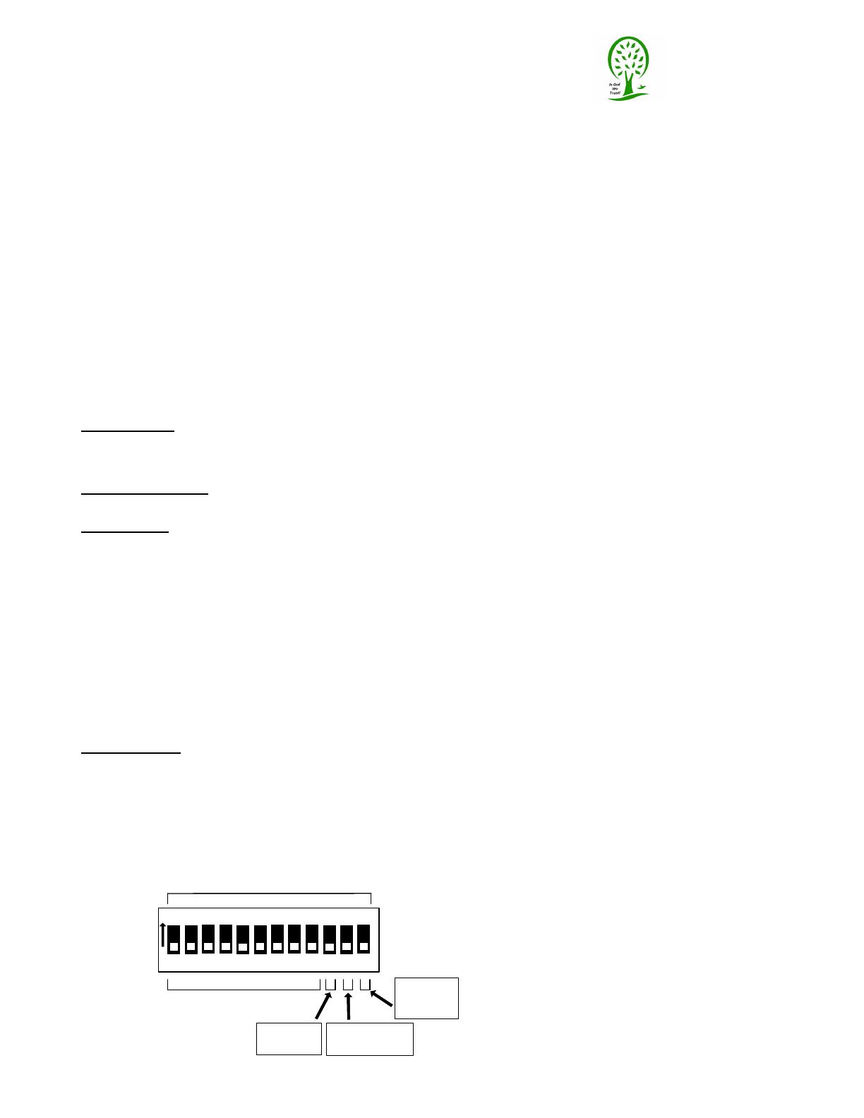
Dip Switches NOTE – A RESET/REPOWER IS REQUIRED FOR ANY DIP SWITCH SETTING CHANGES
Dip Switch’s 1~9: sets the DMX512 start channel
(see the DMX512 Channel Assignment Document). The 1
st
10 volt
output is controlled by the assigned DMX channel, the 2
nd
output is controlled by the assigned DMX channel +1
(consecutively) and so on.
Dip Switch 10: sets the output mode for all outputs - OFF (down position) = VARIABLE MODE – the outputs
vary with the respective DMX levels, ON (up position) = SWITCH MODE - outputs either ON or OFF set by the
threshold values mentioned above.
DIP Switch 11: OFF (down position) = In the Stand Alone Mode (no DMX is present on the input terminal) all of
the outputs will be OFF, ON (up position) = In the Stand Alone Mode all of the outputs will turn ON.
DIP Switch 12: OFF (down position) = Normal Operation, ON (up position) = Hardware Initialization Mode.
When installing or uninstalling a sub module, repower with this switch ON and the yellow LED will flash. Turn
OFF and repower. This will activate or deactivate the specific modules. This sets the internal software settings
for the attached hardware.
DMX512 Input connects to the pins shown above from the DMX512 input XLR connector pins 2 and 3
respectively. Set the terminating switch to “ON” if the DMX signal ends at the DMX input terminal. If the DMX
input terminal is looped to another DMX device (limit 32) then set the terminating switch to “OFF”.
LED Indicators - LED’s to indicate the status of the DMX10V. The power LED will illuminate indicating power is
applied.
DATA LED: ON = indicates DMX data is being received.
OFF = indicates no DMX data is being received and the unit is in Stand Alone Mode
SLOW BLINK = DMX receive error – [overrun error] (reset clears)
FAST BLINK = Communications error(s) with the output circuits (reset clears).
If error continues reinitialize the hardware with the instructions above.
Stand Alone Mode – If a DMX signal is not present the Stand Alone Mode is active. The outputs can be set to
be OFF or Variable via the potentiometer.
DMX10V User Guide
ELM Video Technology, Inc. Copyright 2011-Present
www.elmvideotechnology.com
DMX10V-PCB-User-Guide V7 & V8.vsd
pg 2 of 3
DMX512 Start Channel
Reset Required
Stand Alone Mode
Off=All Off
On=All On
Switch Mode
Off=Variable
On=Switch
Hardware
Initialize
Off=Normal
On=Initialize
Description
ELM Video
Technology, Inc.
“Innovative DMX and MIDI Products”
1 2 3 4 5 6 7 8 9 10 11 12
DMX CONTROL WARNING: NEVER use DMX data devices where human safety must be
maintained. NEVER use DMX data devices for pyrotechnics or similar controls.
Manufacturer: ELM Video Technology
Name: DMX 0 to 10 Volt Analog Converter
Description: Converts a DMX-512 input to a variable 0 to 10 volt analog output
MPN: DX10V-4-DC3P
Model: DX10V
CHASSIS: Anodized Aluminum .093" thick RoHS compliant
Internal Fuse: SMT 750mA
Power Input: +12VDC apx 400mA (values apx, some circuits may vary)
4 Channel: no load:64mA full load 145mA
8 Channel: no load 70mA full load 230mA
16 Channel: no load 82mA full load 402mA
Voltage Output: 0~10VDC, (500 ohm minimum load)
Source Output Current: 20mA Max each
Sink Output Current: 10mA Max each
DATA TYPE: DMX (250Khz)
Data Input: 5 (or 3) pin male XLR
[Pin 1 Not connected, Pin 2Data -, Pin 3 Data +]
Data Loop Output: (If equipped) 5 (or 3) pin female XLR,
[Pin 1 Looped from pin 1 of input XLR, Pin 2Data -, Pin 3 Data +]
Dimensions: 3.7 x 6.7 x 2.1 inches
Weight: 1.5 pounds
Operating temperature: 32°F to 100°F
Storage temperature: 0°F to 120°F
Humidity: Non condensing
Refresh Rate Per Second:
Version 7: 4 Ch's = 3067, 8 Ch's = 1512, 12 Ch's = 1022, 16 Ch's = 746
Version 8: 8 Ch's = 1502, 16 Ch's = 739, 24 Ch's = 506
(amount of times per second the outputs are updated)
Output Connections: 9 Pin terminal block
External Power Supply: +12VDC wall mount
Voltage Input: 100 ~ 132 (or 240) VAC
Current Output (Min): 1 Amps
Power (Min): 12 Watts
Polarization: Positive Center
Output Connector: Locking Barrel Plug, 2.1mm I.D. x 5.5mm O.D. x 9.5mm
DMX10V User Guide
pg 3 of 3
Specifications
ELM Video
Technology, Inc.
“Innovative DMX and MIDI Products”
ELM Video Technology, Inc. Copyright 2011-Present
www.elmvideotechnology.com
DMX10V-PCB-User-Guide V7 & V8.vsd
  • Page 1 1
  • Page 2 2
  • Page 3 3

ELM Video DX10V User guide

Category
Stroboscopes & disco lights
Type
User guide

ELM Video DX10V is a versatile DMX to 0-10 Volt Converter, Switch, and Solid State Relay Driver. Easily control any 0-10V analog equipment with a DMX source, converting DMX data into variable voltage outputs. With both Variable and Switch modes, you can achieve precise voltage adjustments or use the device as a solid-state relay driver.

Ask a question and I''ll find the answer in the document

Finding information in a document is now easier with AI