Page is loading ...

Z6/Z6T/Z6S/Z6W
Z6 Pro/Z6 Expert/Z6Vet
Z8/Z8S/Z8 Pro/Z8 Expert
Diagnostic Ultrasound System
Service Manual
Revision 5.0


i
Table of Content
Table of Content................................................................................................................... i
Revision History .................................................................................................................. I
Intellectual Property Statement .......................................................................................... I
Applicable for....................................................................................................................... I
Statement ............................................................................................................................ II
Responsibility on the Manufacturer Party ........................................................................ II
Customer Service Department ........................................................................................... II
1 Preface....................................................................................................................... 1-1
1.1 Meaning of Signal Words ................................................................................................. 1-1
1.2 Meaning of Symbols ........................................................................................................ 1-1
1.2.1 Meaning of Safety Symbols ...................................................................................... 1-1
1.2.2 Warning Labels ........................................................................................................ 1-2
1.2.3 General Symbols ..................................................................................................... 1-2
1.3 Safety Precautions .......................................................................................................... 1-4
1.3.1 Electric safety .......................................................................................................... 1-4
1.3.2 Mechanical Safety .................................................................................................... 1-5
1.3.3 Personnel Safety ...................................................................................................... 1-5
1.3.4 Other ....................................................................................................................... 1-5
2 Product Specifications ............................................................................................. 2-1
2.1 Overview ......................................................................................................................... 2-1
2.1.1 Intended Use ........................................................................................................... 2-1
2.1.2 Introduction of Each Unit .......................................................................................... 2-1
2.1.3 Peripherals Supported ............................................................................................. 2-7
2.2 Specifications .................................................................................................................. 2-8
2.2.1 Dimensions and Weight ........................................................................................... 2-8
2.2.2 Electrical Specifications ............................................................................................ 2-8
2.2.3 Environmental Conditions......................................................................................... 2-8
2.2.4 Monitor Specification ................................................................................................ 2-8
3 System Installation ................................................................................................... 3-1
3.1 Preparations for Installation ............................................................................................. 3-1
3.1.1 Electrical Requirements ........................................................................................... 3-1
3.1.2 Installation Condition ................................................................................................ 3-2
3.2 Unpacking ....................................................................................................................... 3-2
3.2.1 Unpacking ................................................................................................................ 3-3
3.2.2 Checking.................................................................................................................. 3-5
3.3 Installation of Main Unit ................................................................................................... 3-5
3.3.1 Installing Battery ...................................................................................................... 3-5
3.3.2 Control Panel Adjusting ............................................................................................ 3-5
3.3.3 Display Adjusting ...................................................................................................... 3-6
3.3.4 Installing Probe Holder ............................................................................................. 3-7
3.3.5 Connecting a Probe ................................................................................................. 3-7
3.4 Installing Peripherals ....................................................................................................... 3-8
3.4.2 Video Printer Installation........................................................................................... 3-8
3.4.3 Installing a Graph / Text Printer ................................................................................ 3-9

ii
3.4.4 Installing External DVD-R/W .................................................................................... 3-9
3.5 System Configuration .................................................................................................... 3-10
3.5.1 Power ON / OFF .................................................................................................... 3-10
3.5.2 Enter Doppler ......................................................................................................... 3-10
3.5.3 System Preset ........................................................................................................ 3-11
3.5.4 Print Preset ............................................................................................................ 3-13
3.5.5 Network Preset ...................................................................................................... 3-15
3.5.6 System Information ................................................................................................ 3-18
4 Hardware Principle ................................................................................................... 4-1
4.1 General Structure of Hardware System ............................................................................ 4-1
4.2 Main Unit ......................................................................................................................... 4-2
4.2.1 Probe Board............................................................................................................. 4-2
4.2.2 Main board ............................................................................................................... 4-3
4.2.3 IO Broad .................................................................................................................. 4-5
4.2.4 4D Drive Board ........................................................................................................ 4-6
4.2.5 Ultrasound System Monitor ...................................................................................... 4-7
4.2.6 Ultrasound System Indicator .................................................................................... 4-8
4.2.7 Display ..................................................................................................................... 4-9
4.2.8 Control Panel ......................................................................................................... 4-10
4.3 Power System ................................................................................................................ 4-11
4.3.1 Power Output of the Power Supply module and Supporting Function Distribution .... 4-11
4.3.2 System Power-on Control ...................................................................................... 4-12
5 Function and Performance Checking Method ........................................................ 5-1
5.1 Instruction ....................................................................................................................... 5-1
5.2 Checking System Status .................................................................................................. 5-1
5.2.1 System Running Status ............................................................................................ 5-1
5.2.2 System Running Status ............................................................................................ 5-1
5.3 General exam.................................................................................................................. 5-2
5.3.1 Check Flow .............................................................................................................. 5-2
5.3.2 Checking Content .................................................................................................... 5-2
5.4 Function Checks.............................................................................................................. 5-4
5.4.1 Check Flow .............................................................................................................. 5-5
5.4.2 Checking Content .................................................................................................... 5-5
5.5 Performance Test .......................................................................................................... 5-12
5.5.1 Test Process .......................................................................................................... 5-12
5.5.2 Test Content........................................................................................................... 5-12
6 Software Upgrade and Maintenance ........................................................................ 6-1
6.1 Enter the Maintenance Window.......................................................................................... 6-1
6.2 System Software Installation/ Restoration ........................................................................ 6-2
6.3 Installation of Optional Devices ........................................................................................ 6-2
6.4 Data Backup and Storage ................................................................................................ 6-5
6.4.1 Manage Settings ...................................................................................................... 6-5
6.4.2 Patient Data Backup and Restore............................................................................. 6-6
6.5 Software Maintenance ..................................................................................................... 6-7
6.5.1 Product Configuration .............................................................................................. 6-7
6.5.2 Log Maintenance ..................................................................................................... 6-7
6.6 Display Parameter Setting ............................................................................................... 6-9
6.7 HDD Partition ................................................................................................................ 6-10
7 Structure and Assembly/Disassembly .................................................................... 7-1

iii
7.1 Structure of the Complete System ................................................................................... 7-1
7.2 Field Replaceable Unit .................................................................................................... 7-2
7.3 Preparations .................................................................................................................. 7-13
7.3.1 Tools Required ....................................................................................................... 7-13
7.3.2 Engineers Required ............................................................................................... 7-13
7.3.3 Assembly/Disassembly Required ........................................................................... 7-13
7.4 Assembly/Disassembly .................................................................................................. 7-13
7.4.1 Battery Connecting Board ...................................................................................... 7-14
7.4.2 Power Supply Module ............................................................................................ 7-16
7.4.3 IO Broad ................................................................................................................ 7-19
7.4.4 Probe Board........................................................................................................... 7-20
7.4.5 Main Board and CPU Module ................................................................................. 7-21
7.4.6 Top Cover Assembly of Keyboard ........................................................................... 7-23
7.4.7 Display Assembly ................................................................................................... 7-27
7.4.8 Hard Disk ............................................................................................................... 7-31
7.4.9 Speaker ................................................................................................................. 7-32
8 System Diagnosis and Support ............................................................................... 8-1
8.1 General Status Indicator .................................................................................................. 8-1
8.1.1 Status Indicators of the Control Panel ....................................................................... 8-1
8.1.2 Status Indicator of the Power Supply on the IO Board ............................................... 8-2
8.1.3 Status of whole machine .......................................................................................... 8-2
8.2 Starting Process of the Whole System ............................................................................. 8-3
8.2.1 Start Process of Complete System ........................................................................... 8-4
8.2.2 Start-up Process of BIOS ......................................................................................... 8-5
8.2.3 Start-up of Linux ....................................................................................................... 8-5
8.2.4 Start-up of Doppler ................................................................................................... 8-6
8.3 Alarming and Abnormal Information ................................................................................. 8-8
8.3.1 Turning on the System Configuration File is Abnormal .............................................. 8-9
8.3.2 The voltage of system power is abnormal ................................................................. 8-9
8.3.3 Temperature Alarming .............................................................................................. 8-9
8.3.4 Fan Alarming .......................................................................................................... 8-10
8.3.5 Battery Alarming..................................................................................................... 8-10
8.3.6 PHV Related Alarming............................................................................................. 8-11
9 Care and Maintenance .............................................................................................. 9-1
9.1 Overview ......................................................................................................................... 9-1
9.1.1 Tools, Measurement Devices and Consumables....................................................... 9-1
9.1.2 Care and Maintenance Items ................................................................................... 9-2
9.2 Cleaning .......................................................................................................................... 9-3
9.2.1 Clean the System ..................................................................................................... 9-3
9.2.2 Content .................................................................................................................... 9-3
9.2.3 Clean the Peripherals ............................................................................................... 9-6
9.3 Checking ......................................................................................................................... 9-6
9.3.1 General check .......................................................................................................... 9-6
9.3.2 System Function Check ........................................................................................... 9-7
9.3.3 Peripherals and Options Check ................................................................................ 9-8
9.3.4 Mechanical Safety Inspection ................................................................................... 9-8
9.3.5 Electrical Safety Inspection ...................................................................................... 9-9
10 Troubleshooting of Regular Malfunctions............................................................. 10-1
10.1 System cannot be powered on ...................................................................................... 10-1

iv
10.1.1 Module or Board Related ....................................................................................... 10-1
10.1.2 Key Points Supporting Troubleshooting .................................................................. 10-1
10.1.3 Troubleshooting ..................................................................................................... 10-1
10.2 System Cannot Start up Normally .................................................................................. 10-2
10.2.1 Module or Board Related ....................................................................................... 10-2
10.2.2 Key Points Supporting Troubleshooting .................................................................. 10-2
10.2.3 Troubleshooting ..................................................................................................... 10-2
10.3 Image Fault ................................................................................................................... 10-3
10.3.1 Module or Board Related ....................................................................................... 10-3
10.3.2 Key Points Supporting Troubleshooting .................................................................. 10-4
10.3.3 Troubleshooting ..................................................................................................... 10-4
10.4 Probe Socket System Malfunction ................................................................................. 10-5
10.4.1 Module or Board Related ....................................................................................... 10-5
10.4.2 Key Points Supporting Troubleshooting .................................................................. 10-5
10.4.3 Troubleshooting ..................................................................................................... 10-5
10.5 IO Interface System ....................................................................................................... 10-6
10.5.1 Module or Board Related ....................................................................................... 10-6
10.5.2 Key Points Supporting Troubleshooting .................................................................. 10-6
10.5.3 Troubleshooting ..................................................................................................... 10-6
10.6 Control Panel ................................................................................................................ 10-7
10.6.1 Module or Board Related ....................................................................................... 10-7
10.6.2 Key Points Supporting Troubleshooting .................................................................. 10-7
10.6.3 Troubleshooting ..................................................................................................... 10-7
10.7 LCD Display .................................................................................................................. 10-8
10.7.1 Module or Board Related ....................................................................................... 10-8
10.7.2 Key Points Supporting Troubleshooting .................................................................. 10-8
10.7.3 Troubleshooting ..................................................................................................... 10-8
Appendix A ELECTRICAL SAFETY INSPECTION....................................................A-1
Appendix B Phantom Usage Illustration..................................................................B-1

I
Revision History
Mindray may revise this publication from time to time without written notice.
Revision
Date
Reason for Change
1.0
2016.12
Initial release
2.0
2017.11.20
In section 7.2, update the HDD assembly and ECG assembly for Z6
VET system due to incompatible version update
3.0
2018.8
Add part numbers of AC-DC board and DC-DC board in chapter 7
4.0
2019.8
Add part number of CPU Module and relevant comments in chapter 7
5.0
2019.9
Update part number of main board
© 2019 Shenzhen Mindray Bio-medical Electronics Co., Ltd. All Rights Reserved.
Intellectual Property Statement
SHENZHEN MINDRAY BIO-MEDICAL ELECTRONICS CO., LTD. (hereinafter called Mindray)
owns the intellectual property rights to this Mindray product and this manual. This manual may
referring to information protected by copyright or patents and does not convey any license under
the patent rights or copyright of Mindray, or of others.
Mindray intends to maintain the contents of this manual as confidential information. Disclosure of
the information in this manual in any manner whatsoever without the written permission of Mindray
is strictly forbidden.
Release, amendment, reproduction, distribution, rental, adaptation, translation or any other
derivative work of this manual in any manner whatsoever without the written permission of Mindray
is strictly forbidden.
, , , , , BeneView, WATO,
BeneHeart, are the trademarks, registered or otherwise, of Mindray in China and other
countries. All other trademarks that appear in this manual are used only for informational or
editorial purposes. They are the property of their respective owners.
Applicable for
This service manual is applicable for the service engineers, authorized service personnel and
service representatives of this ultrasound system.

II
Statement
This service manual describes the product according to the most complete configuration; some of
the content may not apply to the product you are responsible for. If you have any questions, please
contact Mindray Customer Service Department.
Do not attempt to service this equipment unless this service manual has been consulted and is
understood. Failure to do so may result in personnel injury or product damage.
Responsibility on the Manufacturer
Party
Mindray is responsible for the effects on safety, reliability and performance of this product, only if:
All installation operations, expansions, changes, modifications and repairs of this product are
conducted by Mindray authorized personnel;
The electrical installation of the relevant room complies with the applicable national and local
requirements;
The product is used in accordance with the instructions for use.
Mindray's obligation or liability under this warranty does not include any transportation or other
charges or liability for direct, indirect or consequential damages or delay resulting from the improper
use or application of the product or the use of parts or accessories not approved by Mindray or
repairs by people other than Mindray authorized personnel.
This warranty shall not extend to:
Any Mindray product which has been subjected to misuse, negligence or accident;
Any Mindray product from which Mindray's original serial number tag or product identification
markings have been altered or removed;
Any products of any other manufacturers.
Customer Service Department
WARNING:
It is important for the hospital or organization that employs this
equipment to carry out a reasonable service/maintenance plan.
Neglect of this may result in machine breakdown or injury of human
health.
Manufacturer:
Shenzhen Mindray Bio-Medical Electronics Co., Ltd.
Address:
Mindray Building,Keji 12th Road South,High-tech industrial
park,Nanshan,Shenzhen 518057,P.R.China
Website:
www.mindray.com
E-mail Address:
service@mindray.com
Tel:
+86 755 81888998
Fax:
+86 755 26582680

Preface 1-1
1 Preface
This chapter describes important issues related to safety precautions, as well as the labels and
icons on the ultrasound machine.
1.1 Meaning of Signal Words
In this operator’s manual, the signal words DANGER, WARNING, CAUTION and
NOTE are used regarding safety and other important instructions. The signal words and their
meanings are defined as follows. Please understand their meanings clearly before reading this
manual.
Signal word
Meaning
DANGER
Indicates death or serious injury may occur imminently in this
hazardous situation if not avoided.
WARNING
Indicates death or serious injury may occur potentially in this
hazardous situation if not avoided.
CAUTION
Indicates minor or moderate injury may occur potentially in this
hazardous situation if not avoided.
NOTE
Indicates property damage may occur potentially in this hazardous
situation if not avoided.
1.2 Meaning of Symbols
The meaning and location of the safety symbols and warning labels on the ultrasound machine are
described in the following tables, please read them carefully before using the system.
1.2.1 Meaning of Safety Symbols
Symbol
Meaning
Location
Type-BF applied part
The ultrasound probes connected to this system are type-BF
applied parts.
The ECG module connected to this system is Type-BF applied
part.
Above the IO
panel

1-2 Preface
Caution
On the rear
panel
1.2.2 Warning Labels
No.
Warning Labels
Meaning
1.
Please carefully read this manual before use device.
2.
The following labels are
available when the system
works with the mobile
trolley.
a. Do not place the device on a sloped surface. Otherwise the
device may slide, resulting in personal injury or the device
malfunction. Two persons are required to move the device
over a sloped surface.
b. Do not sit on the device.
c. DO NOT push the device. When the casters are locked.
1.2.3 General Symbols
This system uses the symbols listed in the following table, and their meanings are explained as
well.
Symbol
Meaning
Location
Equipotentiality
Power panel
Power button
Upper right corner on the control
panel
Network port
IO panel
USB port
Video output
Remote port

Preface 1-3
VGA port
VGA signal output
AC indicator
Lower left corner on the control
panel
Battery indicator
Standby indicator
Lower right corner on the control
panel
Hard disk indicator
A
Probe connector A
Rear panel
B
Probe connector B
This product is provided with a CE
marking in accordance with the
regulations stated in Council
Directive 93 / 42 / EEC concerning
Medical Devices. The number
adjacent to the CE marking (0123) is
the number of the EU-notified body
certified for meeting the
requirements of the Directive.

1-4 Preface
1.3 Safety Precautions
Please read the following precautions carefully to ensure the safety of the patient and the
operator when using the probes.
DANGER
Do not operate this system in an atmosphere containing flammable or
explosive gases such as anesthetic gases, oxygen, and hydrogen or
explosive fluid such as ethanol because an explosion may occur.
1.3.1 Electric safety
WARNING:
1.
Do connect the power plug of this system and power plugs of
the peripherals to wall receptacles that meet the ratings
indicated on the rating nameplate. Using a multifunctional
receptacle may affect the system grounding performance, and
cause the leakage current to exceed safety requirements.
2.
Do not use any cables other than the cables provided with the
device by Mindray.
3.
Use the cable provided with this system to connect the printer.
Other cables may result in electric shock.
4.
Disconnect the AC power before you clean or uninstall the
ultrasound machine, otherwise, electric shock may result.
5.
Do not use this system simultaneously with equipment such as
an electrosurgical unit, high-frequency therapy equipment, or a
defibrillator, etc.; otherwise electric shock may result.
6.
This system is not water-proof. If any water is sprayed on or
into the system, electric shock may result.
CAUTION:
1.
DO NOT connect or disconnect the system’s power cord or its
accessories (e.g., a printer or a recorder) without turning OFF
the power first. This may damage the system and its
accessories or cause electric shock.
2.
Avoid electromagnetic radiation when perform performance
test on the ultrasound system.
3.
In an electrostatic sensitive environment, don’t touch the
device directly. Please wear electrostatic protecting gloves if
necessary.
4.
You should use the ECG leads provided with the ECG module.
Otherwise it may result in electric shock.

Preface 1-5
1.3.2 Mechanical Safety
WARNING:
1.
When moving the system, you should first power off the
system, fold the LCD display, disconnect the system from
other devices (including probes) and disconnect the system
from the power supply.
2.
Do not subject the probes to knocks or drops. Use of a
defective probe may cause electric shock to the patient.
CAUTION:
1.
Do not expose the system to excessive vibration (during the
transportation) to avoid device dropping, collision, or
mechanical damage.
2.
When you place the system on the mobile trolley and move
them together, you must secure all objects on the mobile trolley
to prevent them from falling. Otherwise you should separate the
system from the mobile trolley and move them individually.
When you have to move the system with the mobile trolley
upward or downward the stairs, you must separate them first
and then move them individually.
3.
Do not move the ultrasound system if the HDD indicator is
green, sudden shake may cause the HDD in damage.
1.3.3 Personnel Safety
NOTE:
1.
The user is not allowed to open the covers and panel of the system, neither
device disassemble is allowed.
2.
To ensure the system performance and safety, only Mindray engineers or
engineers authorized by Mindray can perform maintenance.
3.
Only technical professionals from Mindray or engineers authorized by Mindray
after training can perform maintenance.
1.3.4 Other
NOTE:
For detailed operation and other information about the ultrasound system, please refer
to the operator’s manual.


Product Specifications 2-1
2 Product Specifications
2.1 Overview
2.1.1 Intended Use
Z6 series and Z8 series are diagnostic ultrasound system, which are intended for use in clinical
ultrasonic diagnosis.
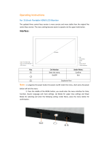
2.1.2 Introduction of Each Unit
Rear view:
1
2
3

2-2 Product Specifications
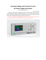
Left side:
9
4
7
5
6
8

Product Specifications 2-3
No.
Name
Function
1
Probe holder
Sets the probe
2
Display
Displays the image and parameters
3
Control Panel
Man-machine interface for operation control, for details,
please refer to “2.1.2.1 Control Panel”.
4
Handle
For lifting the machine
5
IO Panel
Signal input / output panel, for details, please refer to “2.1.2.2
IO Panel”.
6
Power supply
panel
Signal input / output panel, for details, please refer to “2.1.2.3
Power Supply Panel”.
7
Probe sockets
Sockets connecting probes and the main unit
8
Battery cover
Covering battery
9
USB ports
For connecting USB device (2 ports)
2.1.2.1 Control Panel

2-4 Product Specifications
No.
Name
Description
Function
1
/
Power button
Off: when system is turned off;
Green: when system is turned on by pressing this
button.
2
Esc
Exit
Press to exit the current status to the previous
status.
3
Help
/
Press to display or hide the help information on
screen.
4
Patient
Patient
Information
Press to open/ exit patient information screen.
5
Probe
Probe switch
Press to switch Probe and Exam Type
6
Review
/
Press to review the stored images.
7
Report
/
Press to open or close the diagnosis reports.
8
End Exam
/
Press to end an exam.
9
iStation
/
Press to enter or exit the patient information
management system.
10
F1
User-defined key
You can assign a function to the key.
11
Biopsy
/
Press to show or hide the biopsy guide line.
12
Setup
/
Press to open/close the setup menu.
13
Del
/
Press to delete the comment, etc.
14
/
Alphanumeric
keys
Same as on PC
15
Dual
Dual-split screen
Press to enter Dual mode from non-Dual mode;
Press to switch between windows in Dual mode.
16
Quad
Quad-split screen
Press to enter Quad mode from non-quad mode;
Press to switch between windows in Quad mode.
17
Steer
/
Press to activate the steer function for linear probe.
18
/
Direction key
To adjust LCD brightness or contrast when pressing
with <Fn> key.
19
Cine
/
Press to enter or exit the cine review status.
20
Body Mark
/
Press to enter or exit the Body Mark status.
21
Arrow
/
Press to enter or exit the arrow comment status.
22
Clear
/
Press to clear the comments or measurement
calipers on the screen.
23
Scale
/
Press to adjust image parameter of Scale.
24
Baseline
/
Press to adjust image parameter of Baseline.
25
Menu Nav.
/
Multifunction knob
26
/
/
To adjust the image parameter combed with the key
of Scale/Baseline/Nav.Rot

Product Specifications 2-5
No.
Name
Description
Function
27
3D/4D
/
Press to enter or exit the 3D/4D status.
28
Cursor
/
Press to show the cursor.
29
/
Trackball
Roll the trackball to change the cursor position.
30
Set
/
Press to confirm an operation, same as the
left-button of a mouse.
31
PW
/
Press to enter PW mode
32
Color
/
Press to enter Color mode
33
M
/
Press to enter M mode
34
B
/
Press to enter B mode
35
Measure
/
Press to enter/ exit Application Measurement
36
Update
/
Measurement status: press to switch between the
fixed and active end of the caliper;
Multi-imaging mode: press to change the currently
active window.
iScape: press to start/stop image acquisition.
37
Caliper
/
Press to enter/ exit General Measurement
38
Gain/ iTouch
/
Rotate: to adjust the gain
Press: to enter/ exit iTouch
39
TGC
/
Move to adjust time gain compensation.
40
Focus
Freq./THI
/
Press: to switch between Focus and Freq./THI;
Rotate: to adjust corresponding parameter
41
Depth
Zoom
/
Press: to switch between Depth and Zoom;
Rotate: to adjust corresponding parameter
42
Save 1
/
Press to save, user-defined key
43
Save 2
/
Press to save, user-defined key
44
Freeze
/
Press to freeze or unfreeze the image.
45
Print
/
Press to print: user-defined key.
46
/
Indicator 1
AC indicator
AC supply: light green;
Battery supply: light off.
47
/
Indicator 2
Battery status indicator
Charging: light in orange
Full: light in green
Discharge (electricity >20%): light in green
Discharge (electricity <20%): blinking in orange
Discharge (electricity <5%): blinking in orange
rapidly
Non-charge/ discharge: light off

2-6 Product Specifications
No.
Name
Description
Function
48
/
Indicator 3
Standby indicator
Standby: blinking in orange
Other status: light off
49
/
Indicator 4
HDD status indicator
Read/ write: blinking in green
Other status: light off
NOTE: DO NOT move the machine when the
indicator blinking in green. Otherwise the HDD may
be damaged by sudden shake.
50
comment
/
Press to enter or exit the comment status.
2.1.2.2 IO Panel
The IO panel is on the back of the main system.
No.
Symbol
Function
1
Network port
2
USB ports
3
4
Separate video output, connecting video printer or LCD
5
Composite video output
6
Remote control port
7
ECG
ECG port
8
VGA
VGA signal output
9
/
Power indicator
/