Page is loading ...

DITEC S.p.A.
Via Mons. Banfi, 3 - 21042 Caronno Pertusella (VA) - ITALY
Tel. +39 02 963911 - Fax +39 02 9650314
www.ditec.it - [email protected]
E2H
IP1967EN
rev. 2012-07-31
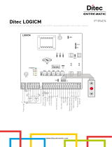
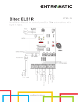
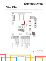
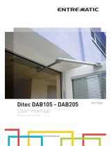
Installation manual for control panel for 2-motor 24V automations with built-in radio.
EN
F1
BATK1
UP
JR5
COM
DOWN
ENTERESC
24V
LN
POWER
TRF
AUX
1 5 9 13
L N
36 35 34
Power supply
JR1
33 32 31 15 14 0 1 5 20 0 1 6 0 1 8
BAT
ANT
Power unit
Memory
card
GOL4
24V= 24V=
Motor2 Motor1
Flashing light
Electric lock
Stop safety contact
Lamp
Step by step
Step by step
Partial opening
Stop
-
+
-
+
Output 24 V=
Output 24 V=
Reversal safety contact

2
,3(1
Subject Page
1. General safety precautions 3
2. EC declaration of conformity 4
3. Technical data 4
3.1 Applications
4
4. Connection of power supply 5
5. Commands 6
5.1 SOFA1-SOFA2 or GOPAVRS self-controlled safety edge
7
6. Outputs and accessories 8
7. Selection 9
8. Signals 9
9. Adjustments 10
9.1 Switching on and off
10
9.2 Key combination
10
9.3 Main menù
11
6HFRQGOHYHOPHQ$7$XWRPDWLF&RQ¿JXUDWLRQV
12
6HFRQGOHYHOPHQ%&%DVLF&RQ¿JXUDWLRQV
13
9.6 Second level menù - BA (Basic Adjustment)
15
9.7 Second level menù - RO (Radio Operations)
19
9.8 Second level menù - SF (Special Functions)
21
9.9 Second level menù - CC (Cycles Counter)
23
9.10 Second level menù - AP (Advanced Parameters)
24
10. Display viewing mode 27
10.1 Automation status display
27
10.2 Commands and safety devices display
27
10.3 Alarms and anomalies display
29
11. Start-up 31
12. Radio receiver operation 32
13. Example application of automation with two swinging door wings 33
14. Example application of automation with one swinging door wings 34
This symbol indicates instructions or notes regarding safety issues which require particular attention.
This symbol indicates instructions or notes intended for technical and expert personnel.
This symbol indicates options and parameters which are only available with the indicated item.
This symbol indicates options and parameters which are not available with the indicated item.
This symbol indicates operations not to be effected for not compromise the correct operation of the
automation.
This symbol indicates informations which are useful for correct product function.
i
STOP
CAPTION
INDEX
All right reserved
$OOGDWDDQGVSHFL¿FDWLRQVKDYHEHHQGUDZQXSDQGFKHFNHGZLWKWKHJUHDWHVWFDUH7KHPDQXIDFWXUHUFDQQRW
KRZHYHUWDNHDQ\UHVSRQVLELOLW\IRUHYHQWXDOHUURUVRPPLVLRQVRULQFRPSOHWHGDWDGXHWRWHFKQLFDORULOOXVWUDWLYH
purposes.

3
,3(1
1. GENERAL SAFETY PRECAUTIONS
This installation manual is intended for professionally competent personnel only.
The installation, the power connections and the settings must be completed in conformity with Good
:RUNLQJ0HWKRGVDQGZLWKWKHUHJXODWLRQVLQIRUFH
%HIRUHLQVWDOOLQJWKHSURGXFWFDUHIXOO\UHDGWKHLQVWUXFWLRQV%DGLQVWDOODWLRQFRXOGEHKD]DUGRXV7KHSDFNDJLQJ
materials (plastic, polystyrene, etc.) should not be discarded in the environment or left within reach of children,
as these are a potential source of hazard.
%HIRUHEHJLQQLQJWKHLQVWDOODWLRQFKHFNWKDWWKHSURGXFWLVLQSHUIHFWFRQGLWLRQ
'RQRWLQVWDOOWKHSURGXFWLQH[SORVLYHDUHDVDQGDWPRVSKHUHVWKHSUHVHQFHRIÀDPPDEOHJDVRUIXPHVUH-
presents a serious threat to safety.
7KHVDIHW\GHYLFHVSKRWRFHOOVVHQVLWLYHHGJHVHPHUJHQF\VWRSHWFPXVWEHLQVWDOOHGWDNLQJLQWRDFFRXQW
WKHSURYLVLRQVDQGWKHGLUHFWLYHVLQIRUFH*RRG:RUNLQJ0HWKRGVWKHLQVWDOODWLRQDUHDWKHIXQFWLRQDOORJLFRI
the system and the forces developed by the automation.
%HIRUHPDNLQJSRZHUFRQQHFWLRQVFKHFNWKDWWKHUDWLQJFRUUHVSRQGVWRWKDWRIWKHPDLQVVXSSO\$PXO-
tipolar disconnection switch with a contact opening gap of at least 3 mm must be included in the mains
VXSSO\&KHFNWKDWXSVWUHDPRIWKHHOHFWULFDOLQVWDOODWLRQDQDGHTXDWHUHVLGXDOFXUUHQWFLUFXLWEUHDNHUDQGDQ
RYHUFXUUHQWFXWRXWDUH¿WWHG
When requested, connect the automation to an effective earthing system carried out as indicated by current
safety regulations.
During installation, maintenance and repair operations, cut off the power supply before opening the cover to
access the electrical parts.
To handle electronic parts, wear earthed antistatic conductive bracelets. The manufacturer of the motorisation
declines all responsibility in the event of components which are not compatible with the safe and correct
operation of the product.
For repairs or replacements of products only original spare parts must be used.

4
,3(1
ARCBH
OBBI3BH
OBBI3BFCH
LUXO3BH
LUXO4BH
FACIL3H
FACIL3EH
Memory module
3M1OB
3M1AR
3M1LX
3M1FC
Power supply 230 V~ 50/60 Hz
F1 fuse F1,6A F1,6A
Motor output 24 V
2x4,5 A max 24 V 2x6 A max
Accessories power supply 24 V
0,5 A 24 V 0,5 A
Temperature min -20 °C max 55 °C min -20 °C max 55 °C
Degree of protection IP55 IP54
Memorizable
radio codes
100
200 [BIXMR2]
100
200 [BIXMR2]
Radio frequency 433,92 MHz 433,92 MHz
i
3. TECHNICAL DATA
2. EC DECLARATION OF CONFORMITY
3.1 Applications
NOTE: the given operating and performance features can only be guaranteed with the use of DITEC
accessories and safety devices.
Manufacturer: DITEC S.p.A.
$GGUHVVYLD0RQV%DQ¿&DURQQR3OOD9$,7$/<
declares that the control panel E2H is in conformity with the provisions of the following EC directives:
EMC Directive 2004/108/EC;
Low Voltage Directive 2006/95/EC
R&TTE Directive 1999/5/EC
Caronno Pertusella, 2010-09-09 Silvano Angaroni
(Managing Director)
Si
S
S
Si
Si
Si
S
S
Si
S
S
Si
S
S
S
S
Si
S
S
Si
Si
S
S
S
S
i
S
Si
S
i
i
i
S
S
Si
i
i
S
S
i
i
S
S
i
i
Si
S
S
i
i
S
S
i
i
i
S
S
i
i
S
S
i
i
i
S
S
S
i
i
i
lvlv
lv
lv
l
lv
l
l
lv
lv
l
l
lv
l
l
l
v
l
l
l
l
l
l
l
lv
v
v
an
an
an
an
an
an
a
o
o
o
An
An
An
An
A
A
An
A
A
An
An
An
A
A
An
An
A
A
A
A
n
AnAn
A
An
A
A
A
A
An
A
A
A
A
n
n
A
A
A
n
An
n
A
A
A
A
A
n
n
A
A
A
A
n
n
n
A
A
A
A
A
n
n
A
A
A
n
n
n
A
A
A
n
n
A
A
A
n
n
n
A
n
n
n
A
n
n
n
A
A
A
n
n
n
n
ga
ga
ga
ga
ga
ga
a
ga
ga
a
a
ga
a
a
ga
a
a
a
a
ga
ga
a
a
a
a
g
g
g
g
g
a
a
a
a
g
g
g
g
a
a
ga
a
ga
g
g
g
g
g
g
g
a
a
a
g
g
g
g
g
g
g
g
g
g
g
g
g
g
g
g
g
g
g
g
g
g
g
ro
ro
ro
ro
ro
ro
ro
ro
ro
ro
ro
ro
ro
o
ro
ro
ro
ro
ro
ro
r
ro
o
o
o
r
ro
o
ro
ro
r
o
o
o
o
o
o
o
ni
ni
n
n
n
n
n
ni
n
n
n
n
i
n
n
n
n
n
n
i
i
n
n
n
n
n
n
n
n
n
i
i
( (
(
(
(
(
(
(
(
(
(
(
(
(
(
(
(
(
(
(
(
(
(
(
(
(
(
(
(
(
(
(
(
(
(
(
(
(
(
(
(
(
(
(
(
(
Ma
M
M
M
M
M
Ma
Ma
Ma
M
M
M
M
Ma
MaMa
Ma
M
M
M
M
M
Ma
M
M
M
Ma
Ma
M
M
M
M
M
M
M
M
Ma
Ma
Ma
Ma
Ma
Ma
Ma
M
M
M
M
M
M
M
Ma
a
a
Ma
a
a
a
M
M
M
M
M
M
M
Ma
a
a
a
a
a
M
M
M
M
M
a
a
a
a
a
M
M
M
M
M
Ma
M
M
a
a
M
M
M
M
M
M
M
Ma
M
M
M
M
M
M
M
M
M
M
M
na
na
n
n
n
n
n
n
n
n
na
na
na
na
na
a
n
n
n
n
n
na
n
n
n
n
gi
g
gi
gi
gi
gi
gi
gi
gi
i
i
gi
gi
i
i
gi
gi
g
g
g
g
g
g
g
g
i
i
g
g
g
g
g
g
g
g
g
gi
i
g
g
g
g
g
g
g
g
i
i
gi
g
g
g
i
i
g
g
i
i
i
g
ng
ngng
g
g
g
g
g
g
ng
g
g
g
g
g
g
g
g
g
g
g
g
g
g
g
g
g
g
g
g
g
g
g
g
g
g
g
g
g
g
g
g
g
g
g
g
g
g
g
g
g
g
g
g
g
g
g
g
g
g
g
g
g
g
g
g
g
g
g
g
g
g
g
g
g
g
g
g
g
g
g
g
g
D
D D
D
D
D
D
D
D
D
D
D
D
D
D
D
D
D
D
D
D
D
D
D
D
D
D
D
D
D
D
D
D
D
D
D
D
D
D
D
D
i
i
i
ir
i
i
i
r
ir
irir
r
r
r
r
r
r
r
r
r
ir
r
r
r
ec
e
e
e
e
ec
ec
ec
ec
ec
e
e
e
e
e
e
e
e
e
e
e
e
e
e
e
e
e
ec
e
e
e
e
e
e
t
t
t
t
t
t
to
o
to
to
to
o
to
to
o
o
r)
r)
r)
)
)
)
)
)

5
,3(1
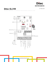
4. CONNECTION OF POWER SUPPLY
%HIRUHFRQQHFWLQJWKHSRZHUVXSSO\PDNHVXUHWKHSODWHGDWDFRUUHVSRQGWRWKDWRIWKHPDLQVSRZHUVXSSO\
An omnipolar disconnection switch with minimum contact gaps of 3 mm must be included in the mains supply.
&KHFNWKDWXSVWUHDPRIWKHHOHFWULFDOLQVWDOODWLRQWKHUHLVDQDGHTXDWHUHVLGXDOFXUUHQWFLUFXLWEUHDNHUDQGD
suitable overcurrent cutout.
Use a H05RN-F 3G1,5 or H05RR-F 3G1,5 type electric cable and connect to the terminals L (brown), N (blue),
(yellow/green) in the automation.
Secure the cable using the special cable clamp and remove the outer sheath near the terminal only.
Connection to the mains power supply, in the section outside the automation, is made with independent chan-
nels and separated from the connections to the control and safety devices.
The channels must penetrate a few centimetres inside the automation thorough a hole maximum Ø16 mm.
0DNHVXUHWKHUHDUHQRVKDUSHGJHVWKDWPD\GDPDJHWKHSRZHUVXSSO\FDEOH
0DNHVXUHWKDWWKHPDLQVSRZHUVXSSO\9FRQGXFWRUVDQGWKHDFFHVVRU\SRZHUVXSSO\9FRQGXF-
tors are separate.

6
,3(1
Command Function Description
1
5 N.O. STEP BY STEP
Selecting
, the closure of the contact
activates a closing or opening operation in the sequence:
open-stop-close-open.
Warning: if automatic closing is enabled, the duration of
the stop is selected via the selection .
OPENING
Selecting
, the closure of the contact
activates an opening operation.
1
6 N.C. SAFETY STOP
Selecting
, the opening of the safety
contact stops and prevents any movement.
Note: to set the different contact safety functions, see the
parameter settings.
1
6 N.O. CLOSING
Selecting
, the closure of the contact
activates a closing operation.
1
8 N.C. REVERSAL SAFETY
CONTACT
The opening of the safety contact triggers a reversal of
motion (re-opening) during a closing operation.
Selecting , with the automation idle,
the opening of the contact prevents any operation.
Selecting , with the automation idle,
the opening of the contact prevents the closing operation
only.
1
9 N.C. STOP Opening the safety contact stops the current operation.
Note: the Àashing light Àashes.
1
9 N.O. HOLD TO RUN FUNCTION
Selecting
and , the
permanent opening of the safety contact enables the hold
to run function.
In this state, the opening (1-5) and closing (1-6) controls
function only if held in the pressed position, and the auto-
mation stops when the controls are released.
Any safety devices, plus the automatic closing, are disa-
bled.
1
20 N.O. PARTIAL OPENING
Selecting
, the closure of the contact
activates a partial opening operation of the door wing
FRPPDQGHGE\PRWRUDQGWKHGXUDWLRQLV¿[HGE\
adjustment .
Warning: if automatic closing is enabled, the duration of
the stop is selected via the adjustment
.
1
20 N.C. AUTOMATIC CLOSING
Selecting
, the permanent closure of
the contact enables automatic closing.
5. COMMANDS
WARNING: Make a jumper on all NC contacts if not in use. The terminals with the same number are
equal

7
,3(1
Command Function Description
SOFA1-SOFA2
GOPAVRS
0411
SAFETY TEST Insert the electronic card SOFA1-SOFA2 or GOPAVRS in the
housing AUX on the control panel.
Selecting
, the terminal 41 activates a safety
edge test before each operation. If the test fails, an alarm message
is visualised on the display.
1 6 N.C. OPENING SAFETY
DEVICE
Selecting
, connect the output contact of device
SOFA1-SOFA2 to terminals 1-6 on the control panel (in series with
the photocell output contact, if installed).
1 8 N.C. REVERSAL
SAFETY
CONTACT
Selecting
, connect the output contact of device
SOFA1-SOFA2 to terminals 1-8 on the control panel (in series
with the photocell output contact, if installed).
5.1 SOFA1-SOFA2 or GOPAVRS self-controlled safety edge

8
,3(1
6. OUTPUT AND ACCESSORIES
Output Value - Accessories
Description
01
+
-
24 V / 0,5 A
Power supply output for external accessories, including automation
status lamp. Electronically protected output.
1
13
24 V
/ 3 W
Automation status lamp (proportional).
The light switches off when the automation is closed; the light switches
RQ ZKHQ WKH DXWRPDWLRQ LV RSHQ WKH OLJKW ÀDVKHV ZLWK D YDULDEOH
frequency while the automation is operating.
0
14
LAMPH
24 V / 25 W
Flashing light (LAMPH). Selecting
WKHÀDVKLQJ
light activates simultaneously with the opening and closing opera-
tion.
NOTE: with automatic closing enabled, there is a preÀashing of 3 s
that cannot be regulated.
0
14
24 V
/ 25 W max.
Courtesy light. Selecting
, it is possible to con-
nect a courtesy light that activates each time a total or partial ope-
ning command or closing command is received.
The duration of the light can be regulated via the adjustment
and .
0
15 24 V / 1,2 A Electric block 24V.
0
15
12V~ / 15 W
Electric lock 12 V.&RQQHFWWKHVXSSOLHG:UHVLVWDQFHLQ
series.
AUX
7KHFRQWUROSDQHOLV¿WWHGZLWKDKRXVLQJIRUDSOXJLQFDUGVXFKDV
radio receivers, magnetic spirals, etc. The action of the card can be
selected via the selection
.
WARNING: the plug-in cards must be inserted and removed with
the power supply disconnected.
COM
Storage
module
The storage module allows remote controls to be stored and the type
RIFRQWUROSDQHODSSOLFDWLRQWREHGH¿QHGVHH7(&+1,&$/'(7$,/6
on page 4).
If the control panel is replaced, the storage module being used can
be inserted in the new control panel.
WARNING: the storage module must be inserted and removed with
the power supply disconnected.
BAT
BATK1
2 x 12 V / 2 Ah
Battery operating. 7KHEDWWHULHVDUHNHSWFKDUJHGZKHQWKHSRZHU
supply is on. If the power supply is off, the control panel is powered
by the batteries until power is re-established or until the battery
voltage drops below the safety threshold. If this occurs, the control
panel turns off.
WARNING: the batteries must always be connected to the control
panel for charging. 3eriodically check the ef¿ciency of the batteries.
NOTE: the operating temperature of the rechargeable batteries is
approximately +5°C/+40°C.

9
,3(1
7. SELECTION
8. SIGNALS
Description OFF ON
JR1 Display mode setting. Visualization mode. It is
only possible to visualize
the values and parameters
present.
Maintenance mode. It is
possible to visualize and
modify the values and pa-
rameters present. The entry
in maintenance mode is
indicated by the permanent
switching on of the right-
hand point.
JR5 Built-in radio receiver. Disabled Enabled
LED ON Flashing
POWER
24 V= power supply. Indicates the transfer of data during
DMCS programming.

10
,3(1
The procedure to switch on the display is as follows:
SUHVVWKH(17(5NH\
VWDUWRIGLVSOD\IXQFWLRQLQJFKHFN
YLVXDOLVDWLRQRI¿UVWOHYHOPHQX
The procedure to switch off the display is as follows:
SUHVVWKH(6&NH\DQGNHHSLWSUHVVHG
NOTE: the display switches off automatically after 60 s of inactivity.
7KHVLPXOWDQHRXVSUHVVLQJRIWKHNH\VS and ENTER performs an opening command.
+ =
7KHVLPXOWDQHRXVSUHVVLQJRIWKHNH\VT and ENTER performs a closing command.
+ =
7KHVLPXOWDQHRXVSUHVVLQJRIWKHNH\VS and T performs a POWER RESET command.
(Interruption of the power supply and restart of the automation).
+ =
9. ADJUSTMENT
9.1 Switching on and off
9.2 Key combinations
NOTE: before making all the automation adjustments, insert the dedicated memory module and press
, or load the con¿guration applying to the automation installed see options. When the
power is connected or in the case of motor non-selection, the display will block all operations and give
an
error message.
WARNING: the pressure on the keys can be quick less than 2 s or prolonged longer than 2 s. 8nless
speci¿ed otherwise, quick pressure is intended.
To con¿rm the setting of a parameter, prolonged pressure is necessary.
i

11
,3(1
XVHWKHNH\VS and T to select the required function
SUHVVWKH(17(5NH\WRFRQ¿UP
Display Description
$7$XWRPDWLF&RQ¿JXUDWLRQV
7KHPHQXDOORZV\RXWRPDQDJHWKHDXWRPDWLFFRQ¿JXUDWLRQVRIWKHFRQWUROSDQHO
%&%DVLF&RQ¿JXUDWLRQV
The menu allows to visualise and modify the main settings of the control panel.
BA - Basic Adjustments.
The menu allows to visualise and modify the main adjustments of the control panel.
RO - Radio Operations.
The menu allows you to manage the radio operations of the control panel.
SF - Special Functions.
The menu allows to set the password and manage the special functions in the control
panel.
CC - Cycles Counter.
The menu allows to visualise the number of operations carried out by the automation, and
manage the maintenance interventions.
AP - Advanced Parameters.
The menu allows to visualise and modify the advanced settings and adjustments of the
control panel.
$IWHUFRQ¿UPLQJWKHVHOHFWLRQ\RXDFFHVVWKHVHFRQGOHYHOPHQX
9.3 Main menu
WARNING: it is possible that, owing to the type of automation and control panel, certain menus are not
available.
i

12
,3(1
Display Description
+3UHGH¿QHGVHWWLQJIRUUHVLGHQWLDOXVH
2 s
+3UHGH¿QHGVHWWLQJIRUUHVLGHQWLDOXVH
2 s
&3UHGH¿QHGVHWWLQJIRUFRQGRPLQLDOXVH
2 s
RD - Resetting the basic settings (SETTINGS RESET).
2 s
- XVHWKHNH\VS and T to select the required function
SUHVVWKH(17(5NH\WRFRQ¿UP
9.4 6HFRQGOHYHOPHQX$7$XWRPDWLF&RQ¿JXUDWLRQV
7KLVVHOHFWLRQORDGVSUHGH¿QHGYDOXHVIRUFHUWDLQVWDQGDUGSDUDPHWHUV
AC - enabling of automatic closing : disabled
C5 - step-by-step/opening command operation : step-by-step
RM - remote control operation : step-by-step
AM - AUX coupling board operation : step-by-step
SS - selection automation status at start up : open
7KLVVHOHFWLRQORDGVSUHGH¿QHGYDOXHVIRUFHUWDLQVWDQGDUGSDUDPHWHUV
AC - enabling of automatic closing : enabled
TC - setting of automatic closing time : 1 minute
C5 - step-by-step/opening command operation : step-by-step
RM - remote control operation : step-by-step
AM - AUX coupling board operation : step-by-step
SS - selection automation status at start up : closed
7KLVVHOHFWLRQORDGVSUHGH¿QHGYDOXHVIRUFHUWDLQVWDQGDUGSDUDPHWHUV
AC - enabling of automatic closing : enabled
TC - setting of automatic closing time : 1 minute
C5 - step-by-step/opening command operation : opening
RM - remote control operation : opening
AM - AUX coupling board operation : opening
SS - selection automation status at start up : open
WARNING: it is possible that, owing to the type of automation and control panel, certain menus are not
available.
i
The procedures to activate the functions are described in the table.

13
,3(1
XVHWKHNH\VS and T to select the required function
SUHVVWKH(17(5NH\WRFRQ¿UP
Display Description
966HOHFWLQJPHFKDQLFDOVWRSVYHUL¿FDWLRQ
When enabled (ON), with every power supply connection
WKH DXWRPDWLRQ DXWRPDWLFDOO\ FKHFNV WKH PHFKDQLFDO
opening and closing end stops and/or the stop limit switches
during opening and closing operation at the speed set with
the adjustment .
During the learning operation, the display visualizes the
message .
OFF ON
NW - Selecting number of door wings.
1 2
AC - Enabling of automatic closing.
OFF ON
C5 - Step-by-step/opening command operation.
STEP-BY-STEP OPENING
RM - Radio receiver functionality.
STEP-BY-STEP OPENING
AM - AUX coupling board operation.
STEP-BY-STEP OPENING
SS - Selection of automation status at activation.
Indicates how the control panel considers the automation at
the time of switch-on, or after a POWER RESET command.
OPEN CLOSED
(/(QDEOHPHQWRIHOHFWULFORFNUHOHDVHVWURNH
:KHQDQHOHFWULFORFNLVSUHVHQWWKHHQDEOHPHQWRIWKHUH-
OHDVHVWURNHLVUHFRPPHQGHG
OFF ON
SO - Enabling reversal safety contact functionality.
When enabled (ON) with the automation idle, if the contact
1-8 is open, all operations are prevented.
When disabled (OFF) with the automation idle, if the contact
1-8 is open, it is possible to activate the opening operation.
OFF ON
9.5 Second level menu - BC (Basic Configurations)

14
,3(1
Display Description
NI - Activation of NIO electronic anti-freeze system.
:KHQHQDEOHG21LWPDLQWDLQVWKHHI¿FLHQF\RIWKHPRWRUV
even in low temperatures.
Note: for correct operation, the control panel must be expo-
sed to the same ambient temperature as the motors.
OFF ON
64 - Functioning of safety stop/closing command.
STOP CLOSING
P2 - Functioning of partial opening command contact 1-20.
P3 - Partial opening command.
1-2 - Enablement of automatic closing
PARTIAL
OPENING
AUTOMATIC
CLOSING
(2)XQFWLRQLQJRIHOHFWULFORFNHOHFWULFEUDNH
6&)XQFWLRQLQJRIHOHFWULFORFNIXQFWLRQLQJWLPHVHWYLD
adjustment )
SF - Functioning of electric magnet powered with auto-
mation closed
ELECTRIC
LOCK
ELECTRIC
MAGNET
FF - Setting function of 0-14 exit.
OF - Courtesy light
ON - Flashing light
COURTESY
LIGHT
FLASHING
LIGHT
WARNING: it is possible that, owing to the type of automation and control panel, certain menus are not
available.
i

15
,3(1
Display Description
MT - Selection of automation type.
NO - None
O3 - OBBI-ARC
F3 - FACIL
L3 - LUXO
NONE
FACIL
OBBI-ARC
LUXO
R1 - Adjustment of motor 1 thrust on obstacles. [%]
7KHFRQWUROSDQHOLV¿WWHGZLWKDVDIHW\GHYLFHZKLFKZKHQ
it detects an obstacle:
- in opening, stops the movement with a disengagement
operation;
- in closing, before the deceleration, inverts the movement;
- in closing, during the deceleration, stops or inverts the
movement according to the type of limit switch installed.
0% 99%
R2 - Adjustment of motor 2 thrust on obstacles. [%]
7KHFRQWUROSDQHOLV¿WWHGZLWKDVDIHW\GHYLFHZKLFKZKHQ
it detects an obstacle:
- in opening, stops the movement with a disengagement
operation;
- in closing, before the deceleration, inverts the movement;
- in closing, during the deceleration, stops or inverts the
movement according to the type of limit switch installed.
0% 99%
RP - Adjustment of the partial opening measurement. [%]
Adjusts the percentage of operation in relation to the total
opening of the automation.
10% 99%
FA - Selection of opening limit switch mode.
NO - None
RA - Deceleration limit switch
(after the activation, the door wing slows down its mo-
vement)
SX - Stop limit switch
(after the activation, the door wing stops its movement)
PX - Proximity limit switch
(after the activation, the door wing continues as far as
the end stop)
NONE
STOP
DECELERATION
PROXIMITY
9.6 Second level menu - BA (Basic Adjustments)
- XVHWKHNH\VS and T to select the required function
SUHVVWKH(17(5NH\WRFRQ¿UP
i
WARNING: the gap between the adjustment values of the parameters may vary according to the type
of automation.
WARNING: it is essential to set the type of automa-
tion before PDNLQJWKHDGMXVWPHQWV

16
,3(1
Display Description
FC - Selection of closing limit switch mode.
NO - None
RA - Deceleration limit switch
(after the activation, the door wing slows down its
movement)
SX - Stop limit switch
(after the activation, the door wing stops its movement)
PX - Proximity limit switc
(after the activation, the door wing continues as far as
the end stop)
NONE
STOP
DECELERATION
PROXIMITY
VA - Setting opening speed. [V]
MIN MAX
VC - Setting closing speed. [V]
MIN MAX
VR - Setting acquisition manoeuvre speed. [V]
MIN MAX
TC - Setting automatic closing time. [s]
Adjustment occurs with intervals of varying sensitivity.
- from 0 to 59 sec with 1 sec intervals;
- from 1 to 2 min with 10 sec intervals.
0 SECONDS
1 MINUTE
59 SECONDS
2 MINUTE
M1 - Setting motor 1 manoeuvre time. [s]
Adjustment, in seconds, of the total manoeuvre time for
motor 1.
Example:
= 7 seconds
= 7,5 seconds
MIN MAX
M2 - Setting motor 2 manoeuvre time. [s]
Adjustment, in seconds, of the total manoeuvre time for
motor 2.
Example:
= 7 seconds
= 7,5 seconds
MIN MAX
i
WARNING: adjustment occurs with a sensitivity inter-
val of 0.5 sec, indicated by the switching on of the
right-hand point.
i
WARNING: adjustment occurs with a sensitivity inter-
val of 0.5 sec, indicated by the switching on of the
right-hand point.
i
WARNING: the acquisition manoeuvre speed can
only be adjusted with the setting .

17
,3(1
Display Description
TR - Setting motor 1 closing delay time. [s]
Adjustment, in seconds, of the delay time for starting the
manoeuvre of motor 1, in relation to motor 2.
MIN MAX
TO - Impostazione tempo di ritardo motore 2 in apertura. [s]
Regolazione in secondi del tempo di ritardo della partenza
di manovra del motore 2 rispetto al motore 1.
MIN MAX
LU - Setting switch-on time for courtesy light. [s]
Adjustment occurs with intervals of varying sensitivity.
- from 0 to 59 sec with 1 sec intervals;
- from 1 to 2 min with 10 sec intervals;
- from 2 to 3 min with 1 min intervals;
NO - Disabled
ON - Permanent switch-on, switch-off using radio
command
i
WARNING: the courtesy light switches on at the start
of each operation.
DISABLED
1 SECOND
1 MINUTE
3 MINUTES
59 SECONDS
2 MINUTES
ON
LG - Setting switch-on time for independent light. [s]
Adjustment occurs with intervals of varying sensitivity.
- from 0 to 59 sec with 1 sec intervals;
- from 1 to 2 min with 10 sec intervals;
- from 2 to 3 min with 1 min intervals;
NO - Disabled
ON - Switch-on and switch-off using radio command
i
WARNING: the switching on of the light does not de-
pend on the start of an operation, but it is possible to
FRQWUROLWVHSDUDWHO\XVLQJWKHUHOHYDQWWUDQVPLWWHUNH\
DISABLED
1 SECOND
1 MINUTE
3 MINUTES
59 SECONDS
2 MINUTES
ON
/56HWWLQJHOHFWULFORFNUHOHDVHWLPH>V@
ON - Active throughout the entire operation
MIN
ON
MAX
TS - Setting renewal of automatic closing time after safety
release. [%]
MIN MAX

18
,3(1
Display Description
:26HWWLQJRSHQLQJSUHÀDVKLQJWLPH>V@
Adjustment, in seconds, of the lead time for the switch-on
RIWKHÀDVKLQJOLJKWLQUHODWLRQWRWKHVWDUWRIWKHPDQRHXYUH
from a voluntary command.
MIN MAX
:&6HWWLQJFORVLQJSUHÀDVKLQJWLPH>V@
Adjustment, in seconds, of the lead time for the switch-on
RIWKHÀDVKLQJOLJKWLQUHODWLRQWRWKHVWDUWRIWKHPDQRHXYUH
from a voluntary command.
MIN MAX
WARNING: it is possible that, owing to the type of automation and control panel, certain menus are not
available.
i

19
,3(1
Display Description
SR - Transmitter memory storage.
...x2, x3...
ER - Deleting a single transmitter.
2 s
EA - Total memory deleting.
2 s 2 s
EC - Deleting a single code. (FUTURE USE)
RE - Setting memory opening from remote control.
When enabled (ON) remote programming is activated. To
memorise new transmitters without using the control panel,
SUHVVDQGKROGGRZQWKH35*NH\RIDQDOUHDG\PHPRULVHG
GOL4 transmitter for 5 seconds until the LED switches on
ZLWKLQWKHFDSDFLW\RIWKHUHFHLYHUDQGSUHVVDQ\&+NH\RI
the new transmitter.
NOTE: make sure that undesired transmitters are not acci-
dently memorized.
OFF ON
MU - Setting the maximum number of transmitters that can
be memorized on a memory module.
It is possible to memorise up to 100 or 200 rolling code
transmitters.
200 100
XVHWKHNH\VS and T to select the required function
SUHVVWKH(17(5NH\WRFRQ¿UP
9.7 Second level menu - RO (Radio Operations)
It is possible to directly access the Transmitter memory storage menu with the display
switched off, but only with Display visualization mode set at 00 or 03:
- by transmitting a remote control not present in the memory,
- by transmitting an unstored channel of a remote control already present in the me-
mory.
The procedures to activate the functions are described in the table.
NOTE: it is necessary to set to allow the
system con¿guration to be saved on the memory mo-
dule

20
,3(1
Display Description
&6HWWLQJNH\IXQFWLRQRIPHPRUL]HGWUDQVPLWWHU
&6HWWLQJNH\IXQFWLRQRIPHPRUL]HGWUDQVPLWWHU
&6HWWLQJNH\IXQFWLRQRIPHPRUL]HGWUDQVPLWWHU
&6HWWLQJNH\IXQFWLRQRIPHPRUL]HGWUDQVPLWWHU
NO - None
1-3 - Opening command
1-4 - Closing command
1-5 - Step-by-step command
P3 - Partial opening command
LG - Courtesy light status change command
1-9 - STOP command
i
WARNING: 1-3 (opening) and 1-5 (step-by-step) are
binary options and are dependent by the
selection.
NONE
CLOSING
PARTIAL
STOP
OPENING
STEP-BY-STEP
COURTESY
LIGHT
5.1DYLJDWLRQYLDWUDQVPLWWHUNH\ERDUG
:LWKWKHGLVSOD\VZLWFKHGRIITXLFNO\W\SHWKHVHTXHQFHRI
NH\V
3
3
2
4
1
using the desired memorized transmit-
ter.
Note: it is recommended to use a dedicated transmitter.
7RWHVWWKHQHZFRQ¿JXUDWLRQVZLWFKRIIWKHGLVSOD\DQGJLYH
DQRSHQFRPPDQGXVLQJNH\
3
.
12
34
1DYLJDWLRQ YLD WUDQVPLWWHU NH\ERDUG LV DXWRPDWLFDOO\ GLVD-
bled after 4 minutes of inactivity or by setting
.
OFF ON
WARNING: during navigation via transmitter keybo-
ard, NONE of the memorized transmitters are active.
i
Warning: it is possible that, owing to the type of automation and control panel, certain menus are not
available.
/