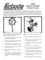
Grizzly G9849 is a highly precise measuring tool that combines a magnetic base with a dial indicator, offering a range of capabilities for various measuring tasks. With a resolution of 0.001", a range of 1", and a 2" easy-to-read dial, this tool enables accurate and quick measurements of runout, lead, and motion. The magnetic base provides versatility, allowing for both tubular and flat mounting surfaces. Additionally, the adjustable markers and dial face lock enhance the tool's functionality, making it suitable for a wide range of applications.
Grizzly G9849 is a highly precise measuring tool that combines a magnetic base with a dial indicator, offering a range of capabilities for various measuring tasks. With a resolution of 0.001", a range of 1", and a 2" easy-to-read dial, this tool enables accurate and quick measurements of runout, lead, and motion. The magnetic base provides versatility, allowing for both tubular and flat mounting surfaces. Additionally, the adjustable markers and dial face lock enhance the tool's functionality, making it suitable for a wide range of applications.


-
 1
1
-
 2
2
-
 3
3
-
 4
4


Grizzly G9849 is a highly precise measuring tool that combines a magnetic base with a dial indicator, offering a range of capabilities for various measuring tasks. With a resolution of 0.001", a range of 1", and a 2" easy-to-read dial, this tool enables accurate and quick measurements of runout, lead, and motion. The magnetic base provides versatility, allowing for both tubular and flat mounting surfaces. Additionally, the adjustable markers and dial face lock enhance the tool's functionality, making it suitable for a wide range of applications.
Ask a question and I''ll find the answer in the document
Finding information in a document is now easier with AI

