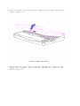
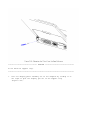
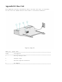
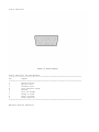
Compaq Aero 2130 User guide
- Category
- Computer case parts
- Type
- User guide
This manual is also suitable for

Notice
The information in this guide is subject to change without notice.
Compaq Computer Corporation shall not be liable for technical or editorial
errors or omissions contained herein; nor for incidental or consequential
damages resulting from the furnishing, performance, or use of this
material.
This guide contains information protected by copyright. No part of this
guide may be photocopied or reproduced in any form without prior written
consent from Compaq Computer Corporation.
Copyright 1994 Compaq Computer Corporation.
All rights reserved. Printed in the USA.
Compaq, Deskpro, LTE, Contura
Registered U.S. Patent and Trademark Office.
Contura Aero is a trademark of Compaq Computer Corporation.
The software described in this guide is furnished under a license agreement
or nondisclosure agreement. The software may be used or copied only in
accordance with the terms of the agreement.
Product names mentioned herein may be trademarks and/or registered
trademarks of their respective companies.
MAINTENANCE AND SERVICE GUIDE
Compaq Contura Aero Family of Personal Computers
First Edition (February 1994)
Part Number 197235-001

Preface
This Maintenance and Service Guide is used for reference when servicing the
Compaq Contura Aero Family of Personal Computers. Additional information
is available in the following publications:
o Compaq Contura Aero Documentation:
- QUICK SETUP
- BEYOND SETUP
- Online USER'S GUIDE
o COMPAQ SERVICE QUICK REFERENCE GUIDE
o Service Training Guides
o Compaq Service Advisories and Bulletins
Compaq Computer Corporation reserves the right to make changes to the
Compaq Contura Aero Family of Personal Computers without notice.
Symbols
The following words and symbols mark special messages throughout this
guide:
>>>>>>>>>>>>>>>>>>>>>>>>>>>>>>>>> WARNING <<<<<<<<<<<<<<<<<<<<<<<<<<<<<<<<<
Text set off in this manner indicates that failure to follow directions in
the warning could result in bodily harm or loss of life.
>>>>>>>>>>>>>>>>>>>>>>>>>>>>>>>>>>>>><<<<<<<<<<<<<<<<<<<<<<<<<<<<<<<<<<<<<<
>>>>>>>>>>>>>>>>>>>>>>>>>>>>>>>>> CAUTION <<<<<<<<<<<<<<<<<<<<<<<<<<<<<<<<<
Text set off in this manner indicates that failure to follow directions
could result in damage to equipment or loss of data.
>>>>>>>>>>>>>>>>>>>>>>>>>>>>>>>>>>>>><<<<<<<<<<<<<<<<<<<<<<<<<<<<<<<<<<<<<<
IMPORTANT: Text set off in this manner presents clarifying information or
specific instructions.
NOTE: Text set off in this manner presents commentary, sidelights, or
interesting points of information.
Technician Notes
>>>>>>>>>>>>>>>>>>>>>>>>>>>>>>>>> WARNING <<<<<<<<<<<<<<<<<<<<<<<<<<<<<<<<<
Only authorized technicians trained by Compaq should repair this equipment.
All troubleshooting and repair procedures are detailed to allow only
subassembly/module level repair. Because of the complexity of the
individual boards and subassemblies, no one should attempt to make repairs
at the component level or to make modifications to any printed circuit
board. Improper repairs can create a safety hazard. Any indications of
component replacement or printed circuit board modifications may void any
warranty.
>>>>>>>>>>>>>>>>>>>>>>>>>>>>>>>>>>>>><<<<<<<<<<<<<<<<<<<<<<<<<<<<<<<<<<<<<<

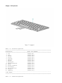
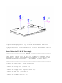
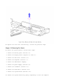
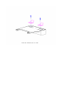
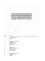
Chapter 1. Illustrated Parts Catalog
Chapter 1.0 Introduction
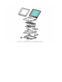
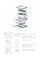
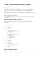
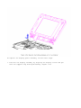
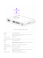
Chapter 1.1 Illustrated Parts Breakdown: Compaq Contura Aero Family Of Personal Computers
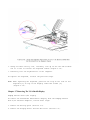
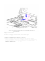
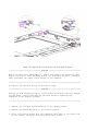
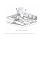
The Compaq Contura Aero Family of Personal Computers joins a display
assembly and system unit together with a clutch secured by screws in the
chassis, display enclosure, and a display pin allowing it to open and
close. The display assembly is secured by screws installed in the front of
the display enclosure. The system unit is secured to the system unit
enclosure by screwlocks in the rear and screws in the bottom of the system
unit enclosure.
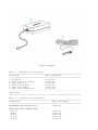
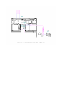
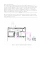
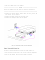
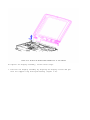
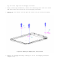
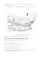
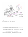
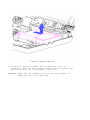
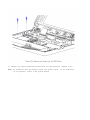
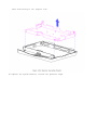
SYSTEM UNIT MODULE DESCRIPTION
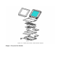
The system unit (Figure 1-4) includes the following replaceable parts:
o Battery and spacer
o Base enclosure
o Keyboard
o Hard drive
o Power supply

o PCMCIA ejector rails
o Trackball assembly
o Memory expansion board (optional)
o System board
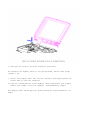
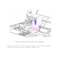
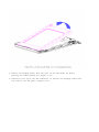
The keyboard is secured to the system unit with four screws and a hook
latch in the front. Once the screws are removed, the keyboard must be
rotated from the rear forward to disengage it from the hook latch. The
keyboard must be removed to allow access to any of the system board
components. The keyboard is connected to the system board with two ribbon
cables and zero insertion force (ZIF) connectors. The cables do not
necessarily have to be disconnected to service the system board. The
keyboard may be laid on top of the battery compartment to access the system
board.
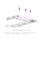
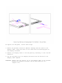
The hard drive is connected directly to the system board with no
intervening cables. It is mounted to the chassis with a hard drive bracket.
The hard drive bracket is secured to the hard drive with three screws.
The power supply is secured to the system board with one threaded standoff.
There is no cable between the power supply and the system board; the power
supply connects directly to the system board.
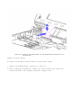
The trackball assembly consists of the trackball, buttons, flex cable, and
speaker. The trackball plugs directly into the cable with a low insertion
force (LIF) connector and mounts with two screws in the right front corner
of the base enclosure. The flex cable includes the buttons and speaker. The
buttons fit in a recessed area on the right side of the base enclosure and
control the functions of the trackball. The speaker is connected to the
flex cable with two wires and fits in a narrow area in the right front
corner of the base enclosure. Sound is directed through the enclosure. The
remainder of the flex cable is routed behind and over the hard drive
assembly and plugs with a LIF connector directly into the system board.
The system board is mounted directly to the chassis. All system module
components connected to the system board must be removed prior to removing
the system board.
The PCMCIA rails are secured to the system board header with two screws at
the top. The rails plug directly into the system board connector.
The memory expansion board plugs into the system board in the bottom of the
base enclosure. Remove the door, and the memory expansion board plugs into
a single connector. System memory can be increased to a maximum 12 MB by
adding an 8 MB Memory Expansion Board. A 4 MB Memory Expansion Board is
also available.
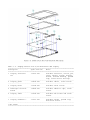
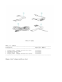
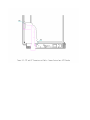
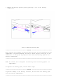
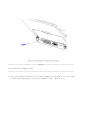
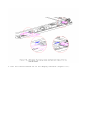
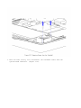
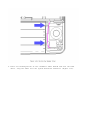
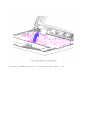
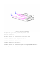
DISPLAY ASSEMBLY MODULE DESCRIPTION
The display assembly (Figures 1-5 and 1-6) includes the following
replaceable parts:
o Display bezel
o Liquid crystal display (LCD) panel
o Display inverter board
o Display cable
o Display shield
o Display enclosure

Compaq Contura Aero 4/25
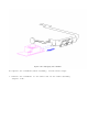
The display assembly is secured with two screws in the bottom corners of
the display bezel and by a screw in a clutch and a pin to the base
enclosure. To remove the display assembly from the base enclosure, the
display bezel must be removed first. Then the CPU cover is removed to allow
access to the system board.
The monochrome LCD is secured to the display enclosure with two screws in
the top left corner and one screw in the top right corner. The bottom
right corner has two small cables attached to a connector for the backlight
and the inverter board.
The display cable is a flex cable plugged into a connector on the left side
of the LCD, folded, and secured to the display shield with a pressure
sensitive adhesive. One end of the display cable is exposed at the bottom
of the display enclosure and is connected to the system board with a zero
insertion force (ZIF) slider. The other end is connected with a low
insertion force (LIF) connector to the display inverter board.
The display inverter board is aligned in the bottom of the display
enclosure with pins. One end connects to the display cable; the other end
plugs into the backlight cable of the LCD panel and is held in place with
pressure sensitive adhesive tape.
The display shield lays in the display enclosure.
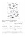
Compaq Contura Aero 4/33C
The display assembly is secured with two screws in the bottom corners of
the display bezel and by a screw in a clutch and a pin to the base
enclosure. To remove the display assembly from the base enclosure, the
display bezel must be removed first. Then the CPU cover is removed to allow
access to the system board.
The color LCD is secured to the display enclosure with four screws in the
corners of the LCD panel. The top right corner has two small cables
attached to a connector for the backlight and the inverter board.
The display cable is a flex cable plugged into a ZIF connector on the left
side of the LCD, folded, and secured to the display shield with a pressure
sensitive adhesive. One end of the display cable is exposed at the bottom
of the display enclosure and is connected to the system board with a ZIF
connector. The other end plugs into a LIF connector on the display inverter
board in the lower right hand corner of the display enclosure.
The display inverter board is aligned on the right side of the display
enclosure and mounted component side down. One end connects to the display
cable; the other end plugs into the backlight cable of the LCD panel.
The display shield lays in the display enclosure and has tabs that bend
over the screw holes of the LCD and secure the display shield to the LCD.


Cha
p
ter 1.2 S
y
stem Unit Module

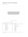
Table 1-1. System Unit
===========================================================================
Description Spare Part No. Notes
===========================================================================
1 Base enclosure 197253-001 Includes screw covers.
---------------------------------------------------------------------------
2 System board, 4 MB Does not include PCMCIA ejector
rails.
Compaq Contura 197241-001 Includes screw covers.
Aero 4/25
Compaq Contura 199222-001
Aero 4/33C
---------------------------------------------------------------------------
3 Door assembly 197239-001 Includes battery and memory
expansion board doors.
---------------------------------------------------------------------------
4 Power supply, DC-DC 190521-001 Includes screw covers.
---------------------------------------------------------------------------
5 Hard drive
- Model 250 199233-001 Does not include hard drive
- Model 170 190661-001 bracket. Includes screw covers.
- Model 84 190660-001
---------------------------------------------------------------------------
6 Memory expansion
board

- 4 MB 190565-001
- 8 MB 190596-001
---------------------------------------------------------------------------
7 Real time clock 117099-001
battery
---------------------------------------------------------------------------
8 NiMH Battery Pack
- 8A: Extended Life 190626-001 Extended Life battery does not
- 8B: Standard 190697-001 include spacer. Standard battery
- 8C: Spacer 197317-001 includes spacer.
---------------------------------------------------------------------------
9 Trackball cable and 197312-001 Includes screw covers.
speaker assembly
---------------------------------------------------------------------------
10 Trackball assembly 197286-001 Includes screw covers.
---------------------------------------------------------------------------
11 Hard drive bracket 197236-001 Includes screws and screw
covers.
---------------------------------------------------------------------------
12 System ROM 197229-001 Includes screw covers.
---------------------------------------------------------------------------
13 CPU cover 197311-001 Includes screw covers.
---------------------------------------------------------------------------
14 CPU chassis 199276-001 Includes clip and screw covers.
===========================================================================
Cha
p
ter 1.3 VGA Dis
p
la
y

Table 1-2. Compaq Contura Aero 4/25 Monochrome VGA Display
===========================================================================
Description Spare Part No. Notes
===========================================================================
1 Display enclosure 197237-001 Includes enclosure, clutch, pin,
kit latch, spring, screws, display
shield, slotted bushing, ground
clip, screw covers and logo.
---------------------------------------------------------------------------
2 Display panel 190624-001 Includes labels, screw covers.
---------------------------------------------------------------------------
3 Display bezel 197344-001 Includes screw covers.
---------------------------------------------------------------------------
4 Backlight inverter 190522-001 Includes adhesive tape, screw
board covers.
---------------------------------------------------------------------------
5 Display cable 197238-001 Includes ZIF slider and screw
covers.
---------------------------------------------------------------------------
6 Display hardware * 197316-001 Includes screws, ground clip,
and screw covers.
---------------------------------------------------------------------------
* Not Shown
===========================================================================

Table 1-3. Compaq Contura Aero 4/33C Color VGA Display
===========================================================================
Description Spare Part No. Notes
===========================================================================
1 Display enclosure 199257-001 Includes enclosure, clutch, pin,
kit latch, spring, screws, display
shield, slotted bushing, screw
covers and logo.
---------------------------------------------------------------------------
2 Display panel 199232-001 Includes labels, screw covers.
---------------------------------------------------------------------------
3 Display bezel 199260-001 Includes screw covers.
---------------------------------------------------------------------------
4 Backlight inverter 199223-001 Includes screw covers.
board
---------------------------------------------------------------------------
5 Display cable 199258-001 Includes ZIF slider and screw
covers.
---------------------------------------------------------------------------
6 Display hardware * 197316-001 Includes screws and screw
covers.
---------------------------------------------------------------------------
* Not Shown
===========================================================================

Chapter 1.4 Keyboards
Table 1-4. Notebook Keyboards
===========================================================================
Description Spare Part Number
===========================================================================
1 U.S. 190620-001
2 U.K. 190620-003 *
3 German 190620-004 *
4 French 190620-005 *
5 Italian 190620-006 *
6 Spanish 190620-007 *
7 Danish 190620-008 *
8 Norwegian 190620-009 *
9 Swedish/Finnish 190620-010 *
10 Swiss 190620-011 *
11 French Canadian 190620-012 *
12 Portuguese 190620-013 *
13 Latin American 190620-016 *
14 Belgium 190620-018 *
15 Japanese 190620-019 *
---------------------------------------------------------------------------
* Not Shown
===========================================================================
Table 1-5. Enhanced Keyboards

===========================================================================
Description Spare Part Number
===========================================================================
1 Enhanced II Keyboard U.S. 112573-001 (No longer
available)*
2 Enhanced III Keyboard U.K. 140536-103 *
3 Enhanced III Keyboard German 140536-104 *
4 Enhanced III Keyboard French 140536-105 *
5 Enhanced III Keyboard Italian 140536-106 *
6 Enhanced III Keyboard Spanish 140536-107 *
7 Enhanced III Keyboard Danish 140536-108 *
8 Enhanced III Keyboard Norwegian 140536-109 *
9 Enhanced III Keyboard Swedish/Finnish 140536-110 *
10 Enhanced III Keyboard Swiss 140536-111 *
11 Enhanced III Keyboard French Canadian 140536-112 *
12 Enhanced III Keyboard Portuguese 140536-113 *
13 Enhanced III Keyboard Turkish 140536-114 *
14 Enhanced III Keyboard Greek 140536-115 *
15 Enhanced III Keyboard Latin American 140536-116 *
16 Enhanced III Keyboard Arabic 140536-117 *
17 Enhanced III Keyboard Belgian 140536-118 *
18 Enhanced III Keyboard Japanese 140536-119 *
19 Enhanced III Keyboard BHCSY ** 140536-120 *
20 Enhanced III Keyboard Hungarian 140536-121 *
21 Enhanced III Keyboard Polish 140536-122 *
22 Enhanced III Keyboard Slovakian 140536-123 *
23 Enhanced III Keyboard Russian 140536-124 *
24 Enhanced III Keyboard Czech 140536-129 *
25 Enhanced III Keyboard Thai 140536-130 *
---------------------------------------------------------------------------
* Not Shown
** Bosnia-Herzegovina, Croatia, Slovenia, and Yugoslavia
===========================================================================
Cha
p
ter 1.5 Cables

Table 1-6. Cables
===========================================================================
Description Spare Part Number
===========================================================================
1 Display Cable (Compaq Contura Aero 4/25) 197238-001
2 Trackball/Speaker Cable 197312-001
3 Communication Cable 197318-001
4 Display Cable (Compaq Contura Aero 4/33C) 199258-001
===========================================================================
Cha
p
ter 1.6 AC Ada
p
ter And Power Cord

Table 1-7. AC Adapter and Power Cord
===========================================================================
Description Spare Part Number
===========================================================================
1 AC Adapter 190621-001
2 Power Cord (U.S./Canada) 197230-001
3 Power Cord (U.K.) 197232-001 *
4 Power Cord (Europe) 197231-001 *
5 Power Cord (Japan) 197233-001 *
6 Power Cord (Asia Pacific) 197234-001 *
---------------------------------------------------------------------------
* Not shown
===========================================================================
Table 1-8. Documentation and Software
===========================================================================
Description Spare Part Number
===========================================================================
MAINTENANCE AND SERVICE GUIDE 197235-001
---------------------------------------------------------------------------
QUICK SETUP CARD, BEYOND SETUP
English 197243-001
German 197243-041
French 197243-051
Italian 197243-061
Spanish 197243-071

---------------------------------------------------------------------------
COMPAQ SERVICE QUICK REFERENCE GUIDE 106854-001
---------------------------------------------------------------------------
LOTUS ORGANIZER MANUAL
English 137885-001
German 137885-041
French 137885-051
Italian 137885-061
Spanish 137885-071
---------------------------------------------------------------------------
Online USER'S GUIDE
English 190512-001
German 190512-041
French 190512-051
Italian 190512-061
Spanish 190512-071
---------------------------------------------------------------------------
WINLINK (diskettes)
English 197330-001
German 197330-041
French 197330-051
Italian 197330-061
Spanish 197330-071
===========================================================================
Table 1-9. Accessories
===========================================================================
Description Spare Part Number
===========================================================================
Automobile adapter 190551-001
Memory expansion board
4 MB 190565-001
8 MB 190596-001
Base unit 190568-001
PCMCIA external diskette drive 190563-001
Mobile port expander 197364-001
Carrying case 121423-001
Briefcase 129930-001
Slipcase cover 197242-001
===========================================================================
Table 1-10. Mounting Hardware
===========================================================================
Description Spare Part Number
===========================================================================
Kit, CPU base screws and screwlocks 197315-001
Kit, display screws 197316-001
Trackball removal tool 194041-001
===========================================================================
Table 1-11a. Fastener List for CPU Base Screws and Screwlocks

===========================================================================
Description Type Where Used Part Number Drive Qty
===========================================================================
M2.5 x 7.0 * Hex System board to 139576-004 3/16 2
chassis
---------------------------------------------------------------------------
M2.5 x 3.55 * Hex Power supply board to 197257-001 3/16 1
chassis
---------------------------------------------------------------------------
#4-40 * Hex I/O connector 106902-004 3/16 4
---------------------------------------------------------------------------
M3.0 x 3.0 Pan Hard drive bracket to 139574-001 PH/1 3
hard drive
---------------------------------------------------------------------------
M2.0 x 7.0 Pan PCMCIA rails to 144762-002 PH/1 2
chassis
---------------------------------------------------------------------------
M2.0 x 2.5 Truss Keyboard to chassis 144863-002 T8/SL 3
---------------------------------------------------------------------------
M2.5 x 12.0 Truss Hard drive to keyboard 144864-005 T8/SL 1
to chassis
---------------------------------------------------------------------------
M2.5 x 6.0 Truss Clutch, system board 144865-003 T8/SL 7
---------------------------------------------------------------------------
M2.5 x 16.0 Truss Base 144865-005 T8/SL 4
---------------------------------------------------------------------------
* Screwlocks
===========================================================================
Table 1-11b. Fastener List for the Compaq Contura Aero 4/25 Display
===========================================================================
Description Type Where Used Part Number Drive Qty
===========================================================================
M2.0 x 4.0 Truss Pin 144863-001 T8/SL 2
M2.5 x 4.5 Truss Clutch 144864-001 T8/SL 2
M2.0 x 6.0 Pan Bezel 197341-002 PH/1 2
M2.0 x 2.5 Truss Panel to enclosure 144863-002 T8/SL 3
===========================================================================
Table 1-11c. Fastener List for the Compaq Contura Aero 4/33C Display
===========================================================================
Description Type Where Used Part Number Drive Qty
===========================================================================
M2.0 x 4.0 Truss Pin and inverter board 144863-001 T8/SL 2
M2.5 x 4.5 Truss Clutch 144864-001 T8/SL 2
M2.0 x 6.0 Pan Bezel 197341-002 PH/1 2
M3.0 x 6.0 Truss Panel to enclosure 198889-001 T8/SL 4
===========================================================================
Table 1-12. Miscellaneous Kits
===========================================================================
Description Spare Part Number
===========================================================================
Base unit tilt feet 197346-001

CPU enclosure feet 197345-001
Battery and memory doors 197239-001
PCMCIA eject rails 197314-001
Carton, quantity 5 137863-001
Carton and buns, quantity 1 137864-001
Display connector slider 140071-001
Plate logo 197251-001
Battery spacer 197317-001
===========================================================================

Chapter 2. Service Preliminaries
Chapter 2.0 Introduction
This chapter provides general service information for the computer and the
base unit.
Adherence to the procedures and precautions described in this chapter is
essential for proper service.
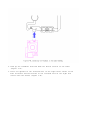
Chapter 2.1 Electrostatic Discharge (International)
A sudden discharge of static electricity from a finger or other conductor
can destroy static sensitive devices or micro circuitry. Often the spark is
neither felt or heard, but damage occurs. An electronic device exposed to
electrostatic discharge (ESD) may not be affected at all and will work
perfectly throughout a normal cycle. Or it may function normally for a
while, then degrade in the internal layers, reducing its life expectancy.
Networks built into many integrated circuits provide some protection, but
in many cases, the discharge contains enough power to alter device
parameters or melt silicon junctions.
Generating Static
Table 2-1 shows how different activities generate static electricity and at
different electrostatic voltage levels.
Table 2-1. Typical Electrostatic Voltages
===========================================================================
Relative Humidity
Event 10% 40% 55%
===========================================================================
Walking across carpet 35,000V 15,000V 7,500V
Walking across vinyl floor 12,000V 5,000V 3,000V
Motions of bench worker 6,000V 800V 400V
Removing DIPS from plastic tubes 2,000V 700V 400V
Removing DIPS from vinyl trays 11,500V 4,000V 2,000V
Removing DIPS from styrofoam 14,500V 5,000V 3,500V
Removing bubble pack from PCBs 26,000V 20,000V 7,000V
Packing PCBs in foam lined box 21,000V 11,000V 5,000V
---------------------------------------------------------------------------
NOTE: 700 volts can degrade a product.
===========================================================================
Preventing Electrostatic Damage To Equipment
Many electronic components are sensitive to ESD. Circuitry design and

structure determine the degree of sensitivity. The following proper
packaging and grounding precautions are necessary to prevent damage:
o Protect all electrostatic parts and assemblies with conductive or
approved containers or packaging.
o Keep electrostatic sensitive parts in their containers until they arrive
at static free stations.
o Place items on a grounded surface before removing them from their
container.
o Always be properly grounded when touching a sensitive component or
assembly.
o Place reusable electronic sensitive parts from assemblies in protective
packaging or conductive foam.
Use transporters and conveyors made of antistatic belts and metal roller
bushings. Mechanized equipment used for moving materials must be wired to
ground and proper materials selected to avoid static charging. When
grounding is not possible, use an ionizer to dissipate electric charges.
Preventing Damage to Drives
To prevent static damage to hard drives, use the following precautions:
o Handle drives gently, using static guarding techniques.
o Store drives in the original shipping containers.
o Avoid dropping drives from any height onto any surface.
o Handle drives on surfaces that have at least one inch of shock proof
foam.
o Always place drives PCB assembly side down on the foam.
Grounding Methods
The method for grounding must include a wrist strap or a foot strap at a
grounded workstation. When seated, wear a wrist strap connected to a
grounded system. When standing, use footstraps and a grounded floor mat.
Table 2-2. Static Shielding Protection Levels
===========================================================================
Method Voltages
===========================================================================
Antistatic Plastic 1,500
Carbon Loaded Plastic 7,500
Metallized Laminate 15,000
===========================================================================
Grounding Workstations
Page is loading ...
Page is loading ...
Page is loading ...
Page is loading ...
Page is loading ...
Page is loading ...
Page is loading ...
Page is loading ...
Page is loading ...
Page is loading ...
Page is loading ...
Page is loading ...
Page is loading ...
Page is loading ...
Page is loading ...
Page is loading ...
Page is loading ...
Page is loading ...
Page is loading ...
Page is loading ...
Page is loading ...
Page is loading ...
Page is loading ...
Page is loading ...
Page is loading ...
Page is loading ...
Page is loading ...
Page is loading ...
Page is loading ...
Page is loading ...
Page is loading ...
Page is loading ...
Page is loading ...
Page is loading ...
Page is loading ...
Page is loading ...
Page is loading ...
Page is loading ...
Page is loading ...
Page is loading ...
Page is loading ...
Page is loading ...
Page is loading ...
Page is loading ...
Page is loading ...
Page is loading ...
Page is loading ...
Page is loading ...
Page is loading ...
Page is loading ...
Page is loading ...
Page is loading ...
Page is loading ...
Page is loading ...
Page is loading ...
Page is loading ...
Page is loading ...
Page is loading ...
Page is loading ...
Page is loading ...
Page is loading ...
Page is loading ...
Page is loading ...
Page is loading ...
Page is loading ...
Page is loading ...
Page is loading ...
Page is loading ...
Page is loading ...
Page is loading ...
Page is loading ...
Page is loading ...
Page is loading ...
Page is loading ...
Page is loading ...
Page is loading ...
Page is loading ...
Page is loading ...
Page is loading ...
Page is loading ...
Page is loading ...
Page is loading ...
Page is loading ...
Page is loading ...
Page is loading ...
Page is loading ...
Page is loading ...
Page is loading ...
Page is loading ...
Page is loading ...
Page is loading ...
Page is loading ...
Page is loading ...
Page is loading ...
Page is loading ...
Page is loading ...
Page is loading ...
Page is loading ...
Page is loading ...
Page is loading ...
Page is loading ...
Page is loading ...
Page is loading ...
Page is loading ...
Page is loading ...
-
 1
1
-
 2
2
-
 3
3
-
 4
4
-
 5
5
-
 6
6
-
 7
7
-
 8
8
-
 9
9
-
 10
10
-
 11
11
-
 12
12
-
 13
13
-
 14
14
-
 15
15
-
 16
16
-
 17
17
-
 18
18
-
 19
19
-
 20
20
-
 21
21
-
 22
22
-
 23
23
-
 24
24
-
 25
25
-
 26
26
-
 27
27
-
 28
28
-
 29
29
-
 30
30
-
 31
31
-
 32
32
-
 33
33
-
 34
34
-
 35
35
-
 36
36
-
 37
37
-
 38
38
-
 39
39
-
 40
40
-
 41
41
-
 42
42
-
 43
43
-
 44
44
-
 45
45
-
 46
46
-
 47
47
-
 48
48
-
 49
49
-
 50
50
-
 51
51
-
 52
52
-
 53
53
-
 54
54
-
 55
55
-
 56
56
-
 57
57
-
 58
58
-
 59
59
-
 60
60
-
 61
61
-
 62
62
-
 63
63
-
 64
64
-
 65
65
-
 66
66
-
 67
67
-
 68
68
-
 69
69
-
 70
70
-
 71
71
-
 72
72
-
 73
73
-
 74
74
-
 75
75
-
 76
76
-
 77
77
-
 78
78
-
 79
79
-
 80
80
-
 81
81
-
 82
82
-
 83
83
-
 84
84
-
 85
85
-
 86
86
-
 87
87
-
 88
88
-
 89
89
-
 90
90
-
 91
91
-
 92
92
-
 93
93
-
 94
94
-
 95
95
-
 96
96
-
 97
97
-
 98
98
-
 99
99
-
 100
100
-
 101
101
-
 102
102
-
 103
103
-
 104
104
-
 105
105
-
 106
106
-
 107
107
-
 108
108
-
 109
109
-
 110
110
-
 111
111
-
 112
112
-
 113
113
-
 114
114
-
 115
115
-
 116
116
-
 117
117
-
 118
118
-
 119
119
-
 120
120
-
 121
121
-
 122
122
-
 123
123
-
 124
124
-
 125
125


Compaq Aero 2130 User guide
- Category
- Computer case parts
- Type
- User guide
- This manual is also suitable for
Ask a question and I''ll find the answer in the document
Finding information in a document is now easier with AI
Related papers
-
Compaq Compaq Portable II User manual
-
-
-
-
-
-
-
Compaq Compaq 1610 Supplementary Manual
-
Compaq Aero 2170 Specification
-
Other documents
-
Everex StepNote NC1501 Quick Setup Manual
-
Alpine AD-SPK1PRO Mounting Bracket Installation guide
-
Sony VGC-RA716G Installation guide
-
Sony VGC-RC110GX Installation guide
-
-
-
 T'nB SLBC16GN Datasheet
-
Classic Exhibits TF-410 Setup Instructions
-
SBS TEAEROIP647T Datasheet
-
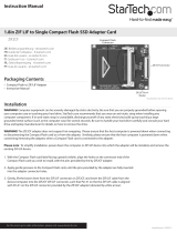 StarTech.com ZIF2CF User manual

