Page is loading ...

• Sales and Service through Subsidiaries and Distributors Worldwide •
Cleveland, Ohio 44117-1199 U.S.A. TEL: 216.481.8100 FAX: 216.486.1751 WEB SITE: www.lincolnelectric.com
• World's Leader in Welding and Cutting Products •
OPERATOR’S MANUAL
IM895
May, 2007
Safety Depends on You
Lincoln arc welding and cutting
equipment is designed and built
with safety in mind. However, your
overall safety can be increased by
proper installation ... and thought-
ful operation on your part. DO
NOT INSTALL, OPERATE OR
REPAIR THIS EQUIPMENT
WITHOUT READING THIS
MANUAL AND THE SAFETY
PRECAUTIONS CONTAINED
THROUGHOUT. And, most
importantly, think before you act
and be careful.
For use with machines having Code Numbers:
Copyright © 2007 Lincoln Global Inc.
PRECISION TIG 225
11317, 11318, 11319
(11320 Ready-Pak)
(11321 Ready-Pak w/Cart)
IP 21S
RETURN TO MAIN MENU

FOR ENGINE
powered equipment.
1.a. Turn the engine off before troubleshooting and maintenance
work unless the maintenance work requires it to be running.
____________________________________________________
1.b. Operate engines in open, well-ventilated
areas or vent the engine exhaust fumes
outdoors.
____________________________________________________
1.c. Do not add the fuel near an open flame
welding arc
or when the engine is running.
Stop the engine and allow it to cool before
refueling to prevent spilled fuel from vaporiz-
ing on contact with hot engine parts and
igniting. Do not spill fuel when filling tank. If
fuel is spilled, wipe it up and do not start
engine until fumes have been eliminated.
____________________________________________________
1.d. Keep all equipment safety guards, covers and devices in
position and
in good repair.Keep hands, hair, clothing and
tools away from V-belts, gears, fans and all other moving
parts when starting, operating or repairing equipment.
____________________________________________________
1.e. In some cases it may be necessary to remove safety
guards to
perform required maintenance. Remove
guards only when necessary and replace them when the
maintenance requiring their removal is complete.
Always use the greatest care when working near moving
parts.
___________________________________________________
1.f. Do not put your hands near the engine fan.
Do not
attempt to override the governor or
idler by pushing on the throttle control rods
while the engine is running.
___________________________________________________
1.g. To prevent accidentally starting gasoline engines while
turning the
engine or welding generator during maintenance
work, disconnect the spark plug wires, distributor cap or
magneto wire as appropriate.
i
SAFETY
i
ARC WELDING CAN BE HAZARDOUS. PROTECT YOURSELF AND OTHERS FROM POSSIBLE SERIOUS INJURY OR DEATH.
KEEP CHILDREN AWAY. PACEMAKER WEARERS SHOULD CONSULT WITH THEIR DOCTOR BEFORE OPERATING.
Read and understand the following safety highlights. For additional safety information, it is strongly recommended that you
purchase a copy of “Safety in Welding & Cutting - ANSI Standard Z49.1” from the American Welding Society, P.O. Box
351040, Miami, Florida 33135 or CSA Standard W117.2-1974. A Free copy of “Arc Welding Safety” booklet E205 is available
from the Lincoln Electric Company, 22801 St. Clair Avenue, Cleveland, Ohio 44117-1199.
BE SURE THAT ALL INSTALLATION, OPERATION, MAINTENANCE AND REPAIR PROCEDURES ARE
PERFORMED ONLY BY QUALIFIED INDIVIDUALS.
WARNING
Mar ʻ95
ELECTRIC AND
MAGNETIC FIELDS
may be dangerous
2.a. Electric current flowing through any conductor causes
localized Electric and Magnetic Fields (EMF). Welding
current creates EMF fields around welding cables and
welding machines
2.b. EMF fields may interfere with some pacemakers, and
welders having a pacemaker should consult their physician
before welding.
2.c. Exposure to EMF fields in welding may have other health
effects which are now not known.
2.d. All welders should use the following procedures in order to
minimize exposure to EMF fields from the welding circuit:
2.d.1.
Route the electrode and work cables together - Secure
them with tape when possible.
2.d.2. Never coil the electrode lead around your body.
2.d.3. Do not place your body between the electrode and
work cables. If the electrode cable is on your right
side, the work cable should also be on your right side.
2.d.4. Connect the work cable to the workpiece as close as
possible to the area being welded.
2.d.5. Do not work next to welding power source.
1.h. To avoid scalding, do not remove the
radiator pressure cap when the engine is
hot.
CALIFORNIA PROPOSITION 65 WARNINGS
Diesel engine exhaust and some of its constituents
are known to the State of California to cause can-
cer, birth defects, and other reproductive harm.
The engine exhaust from this product contains
chemicals known to the State of California to cause
cancer, birth defects, or other reproductive harm.
The Above For Diesel Engines
The Above For Gasoline Engines

ii
SAFETY
ii
ARC RAYS can burn.
4.a. Use a shield with the proper filter and cover
plates to protect your eyes from sparks and
the rays of the arc when welding or observing
open arc welding. Headshield and filter lens
should conform to ANSI Z87. I standards.
4.b. Use suitable clothing made from durable flame-resistant
material to protect your skin and that of your helpers from
the arc rays.
4.c. Protect other nearby personnel with suitable, non-flammable
screening and/or warn them not to watch the arc nor expose
themselves to the arc rays or to hot spatter or metal.
ELECTRIC SHOCK can
kill.
3.a. The electrode and work (or ground) circuits
are electrically “hot” when the welder is on.
Do not touch these “hot” parts with your bare
skin or wet clothing. Wear dry, hole-free
gloves to insulate hands.
3.b. Insulate yourself from work and ground using dry insulation.
Make certain the insulation is large enough to cover your full
area of physical contact with work and ground.
In addition to the normal safety precautions, if welding
must be performed under electrically hazardous
conditions (in damp locations or while wearing wet
clothing; on metal structures such as floors, gratings or
scaffolds; when in cramped positions such as sitting,
kneeling or lying, if there is a high risk of unavoidable or
accidental contact with the workpiece or ground) use
the following equipment:
• Semiautomatic DC Constant Voltage (Wire) Welder.
• DC Manual (Stick) Welder.
• AC Welder with Reduced Voltage Control.
3.c. In semiautomatic or automatic wire welding, the electrode,
electrode reel, welding head, nozzle or semiautomatic
welding gun are also electrically “hot”.
3.d. Always be sure the work cable makes a good electrical
connection with the metal being welded. The connection
should be as close as possible to the area being welded.
3.e. Ground the work or metal to be welded to a good electrical
(earth) ground.
3.f.
Maintain the electrode holder, work clamp, welding cable and
welding machine in good, safe operating condition. Replace
damaged insulation.
3.g. Never dip the electrode in water for cooling.
3.h. Never simultaneously touch electrically “hot” parts of
electrode holders connected to two welders because voltage
between the two can be the total of the open circuit voltage
of both welders.
3.i. When working above floor level, use a safety belt to protect
yourself from a fall should you get a shock.
3.j. Also see Items 6.c. and 8.
FUMES AND GASES
can be dangerous.
5.a. Welding may produce fumes and gases
hazardous to health. Avoid breathing these
fumes and gases. When welding, keep
your head out of the fume. Use enough
ventilation and/or exhaust at the arc to keep
fumes and gases away from the breathing zone. When
welding with electrodes which require special
ventilation such as stainless or hard facing (see
instructions on container or MSDS) or on lead or
cadmium plated steel and other metals or coatings
which produce highly toxic fumes, keep exposure as
low as possible and below Threshold Limit Values (TLV)
using local exhaust or mechanical ventilation. In
confined spaces or in some circumstances, outdoors, a
respirator may be required. Additional precautions are
also required when welding on galvanized steel.
5. b. The operation of welding fume control equipment is affected
by various factors including proper use and positioning of
the equipment, maintenance of the equipment and the spe-
cific welding procedure and application involved. Worker
exposure level should be checked upon installation and
periodically thereafter to be certain it is within applicable
OSHA PEL and ACGIH TLV limits.
5.c.
Do not weld in locations near chlorinated hydrocarbon
vapors
coming from degreasing, cleaning or spraying operations.
The heat and rays of the arc can react with solvent vapors
to
form phosgene, a highly toxic gas, and other irritating prod-
ucts.
5.d. Shielding gases used for arc welding can displace air and
cause injury or death. Always use enough ventilation,
especially in confined areas, to insure breathing air is safe.
5.e. Read and understand the manufacturerʼs instructions for this
equipment and the consumables to be used, including the
material safety data sheet (MSDS) and follow your
employerʼs safety practices. MSDS forms are available from
your welding distributor or from the manufacturer.
5.f. Also see item 1.b.
AUG 06

iii
SAFETY
iii
FOR ELECTRICALLY
powered equipment.
8.a. Turn off input power using the disconnect
switch at the fuse box before working on
the equipment.
8.b. Install equipment in accordance with the U.S. National
Electrical Code, all local codes and the manufacturerʼs
recommendations.
8.c. Ground the equipment in accordance with the U.S. National
Electrical Code and the manufacturerʼs recommendations.
CYLINDER may explode
if damaged.
7.a. Use only compressed gas cylinders
containing the correct shielding gas for the
process used and properly operating
regulators designed for the gas and
pressure used. All hoses, fittings, etc. should be suitable for
the application and maintained in good condition.
7.b. Always keep cylinders in an upright position securely
chained to an undercarriage or fixed support.
7.c. Cylinders should be located:
• Away from areas where they may be struck or subjected to
physical damage.
• A safe distance from arc welding or cutting operations and
any other source of heat, sparks, or flame.
7.d. Never allow the electrode, electrode holder or any other
electrically “hot” parts to touch a cylinder.
7.e. Keep your head and face away from the cylinder valve outlet
when opening the cylinder valve.
7.f. Valve protection caps should always be in place and hand
tight except when the cylinder is in use or connected for
use.
7.g. Read and follow the instructions on compressed gas
cylinders, associated equipment, and CGA publication P-l,
“Precautions for Safe Handling of Compressed Gases in
Cylinders,” available from the Compressed Gas Association
1235 Jefferson Davis Highway, Arlington, VA 22202.
Jan, 07
WELDING and CUTTING
SPARKS can
cause fire or explosion.
6.a.
Remove fire hazards from the welding area.
If this is not possible, cover them to prevent
the welding sparks from starting a fire.
Remember that welding sparks and hot
materials from welding can easily go through small cracks
and openings to adjacent areas. Avoid welding near
hydraulic lines. Have a fire extinguisher readily available.
6.b. Where compressed gases are to be used at the job site,
special precautions should be used to prevent hazardous
situations. Refer to “Safety in Welding and Cutting” (ANSI
Standard Z49.1) and the operating information for the
equipment being used.
6.c. When not welding, make certain no part of the electrode
circuit is touching the work or ground. Accidental contact
can cause overheating and create a fire hazard.
6.d. Do not heat, cut or weld tanks, drums or containers until the
proper steps have been taken to insure that such procedures
will not cause flammable or toxic vapors from substances
inside. They can cause an explosion even
though
they have
been “cleaned”. For information, purchase “Recommended
Safe Practices for the
Preparation
for Welding and Cutting of
Containers and Piping That Have Held Hazardous
Substances”, AWS F4.1 from the American Welding Society
(see address above).
6.e. Vent hollow castings or containers before heating, cutting or
welding. They may explode.
6.f.
Sparks and spatter are thrown from the welding arc. Wear oil
free protective garments such as leather gloves, heavy shirt,
cuffless trousers, high shoes and a cap over your hair. Wear
ear plugs when welding out of position or in confined places.
Always wear safety glasses with side shields when in a
welding area.
6.g. Connect the work cable to the work as close to the welding
area as practical. Work cables connected to the building
framework or other locations away from the welding area
increase the possibility of the welding current passing
through lifting chains, crane cables or other alternate cir-
cuits. This can create fire hazards or overheat lifting chains
or cables until they fail.
6.h. Also see item 1.c.
6.I. Read and follow NFPA 51B “ Standard for Fire Prevention
During Welding, Cutting and Other Hot Work”, available
from NFPA, 1 Batterymarch Park,PO box 9101, Quincy, Ma
022690-9101.
6.j. Do not use a welding power source for pipe thawing.

viivii
Thank You
for selecting a QUALITY product by Lincoln Electric. We want you
to take pride in operating this Lincoln Electric Company product
••• as much pride as we have in bringing this product to you!
Read this Operators Manual completely before attempting to use this equipment. Save this manual and keep it
handy for quick reference. Pay particular attention to the safety instructions we have provided for your protection.
The level of seriousness to be applied to each is explained below:
WARNING
This statement appears where the information must be followed exactly to avoid serious personal injury or loss of life.
This statement appears where the information must be followed to avoid minor personal injury or damage to this equipment.
CAUTION
Please Examine Carton and Equipment For Damage Immediately
When this equipment is shipped, title passes to the purchaser upon receipt by the carrier. Consequently, Claims
for material damaged in shipment must be made by the purchaser against the transportation company at the
time the shipment is received.
Please record your equipment identification information below for future reference. This information can be
found on your machine nameplate.
Product _________________________________________________________________________________
Model Number ___________________________________________________________________________
Code Number or Date Code_________________________________________________________________
Serial Number____________________________________________________________________________
Date Purchased___________________________________________________________________________
Where Purchased_________________________________________________________________________
Whenever you request replacement parts or information on this equipment, always supply the information you
have recorded above. The code number is especially important when identifying the correct replacement parts.
On-Line Product Registration
- Register your machine with Lincoln Electric either via fax or over the Internet.
• For faxing: Complete the form on the back of the warranty statement included in the literature packet
accompanying this machine and fax the form per the instructions printed on it.
• For On-Line Registration: Go to our
WEB SITE at www.lincolnelectric.com. Choose “Quick Links” and then
“Product Registration”. Please complete the form and submit your registration.
CUSTOMER ASSISTANCE POLICY
The business of The Lincoln Electric Company is manufacturing and selling high quality welding equipment, consumables, and cutting equip-
ment. Our challenge is to meet the needs of our customers and to exceed their expectations. On occasion, purchasers may ask Lincoln
Electric for advice or information about their use of our products. We respond to our customers based on the best information in our posses-
sion at that time. Lincoln Electric is not in a position to warrant or guarantee such advice, and assumes no liability, with respect to such infor-
mation or advice. We expressly disclaim any warranty of any kind, including any warranty of fitness for any customerʼs particular purpose,
with respect to such information or advice. As a matter of practical consideration, we also cannot assume any responsibility for updating or
correcting any such information or advice once it has been given, nor does the provision of information or advice create, expand or alter any
warranty with respect to the sale of our products.
Lincoln Electric is a responsive manufacturer, but the selection and use of specific products sold by Lincoln Electric is solely within the control
of, and remains the sole responsibility of the customer. Many variables beyond the control of Lincoln Electric affect the results obtained in
applying these types of fabrication methods and service requirements.
Subject to Change – This information is accurate to the best of our knowledge at the time of printing. Please refer to www.lincolnelectric.com
for any updated information.

viii
viii
TABLE OF CONTENTS
Page
Installation.......................................................................................................................Section A
Technical Specifications ................................................................................................A-1,A-2
Safety Precautions ...............................................................................................................A-3
Select Suitable Location................................................................................................A-3
Environmental Rating....................................................................................................A-3
Grinding.........................................................................................................................A-3
Stacking ........................................................................................................................A-3
Lifting and Moving .........................................................................................................A-3
Tilting.............................................................................................................................A-3
Machine Grounding and High Frequency Interference Protection .......................................A-4
Input and Grounding Connections ................................................................................A-4
Input Reconnect Procedure ..........................................................................................A-5
Output Connections..............................................................................................................A-5
Connections For Tig (GTAW) Welding..........................................................................A-6
Tig Torch Connections ..................................................................................................A-6
Work Cable Connections ..............................................................................................A-6
Shielding Gas Connection.............................................................................................A-6
Remote Control Connection..........................................................................................A-6
Connections For Stick (SMAW) Welding .............................................................................A-6
Stick Electrode Cable and Work Cable Connection......................................................A-6
________________________________________________________________________________
Operation.........................................................................................................................Section B
Safety Precautions ...............................................................................................................B-1
Graphic Symbols ..................................................................................................................B-1
Product Description ..............................................................................................................B-2
Recommended Processes and Equipment ..........................................................................B-2
Recommended Processes.. ..........................................................................................B-2
Process Limitations ......................................................................................................B-2
Recommended Equipment/Interface.............................................................................B-2
Equipment Limitations...................................................................................................B-2
Welding Capability................................................................................................................B-2
Controls and Settings ...................................................................................................B-3, B-4
Power-Up Sequence ............................................................................................................B-4
Case Rear Components.......................................................................................................B-5
Operating Steps ...................................................................................................................B-6
Welding in TIG Mode ....................................................................................................B-6
Pulse TIG Mode ............................................................................................................B-6
Remote Control Operation ............................................................................................B-7
Benefits of the Precision TIG 225 .................................................................................B-7
Welding in Stick Mode..........................................................................................................B-8
Recommended electrode Amperage Ranges ......................................................................B-9
________________________________________________________________________________
Accessories.....................................................................................................Section C
Standard Equipment Options ................................................................................C-1
Factory Installed Options.......................................................................................C-2
Field Installed Options...........................................................................................C-3
________________________________________________________________________
Maintenance ....................................................................................................Section D
Safety Precautions ................................................................................................D-1
Routine and Periodic Maintenance........................................................................D-1
Spark Gap Adjustment ..........................................................................................D-1
________________________________________________________________________
Troubleshooting..............................................................................................Section E
Safety Precautions.................................................................................................E-1
How to Use Troubleshooting Guide.......................................................................E-1
Troubleshooting ..................................................................................E-2 THRU E-7
________________________________________________________________________
Diagrams .........................................................................................................Section F
Wiring Diagram ......................................................................................................F-1
Dimension Print ...............................................................................................F-2,F-3
________________________________________________________________________
Parts List..................................................................................P-536,P-210,P-66 Series
_______________________________________________________________________

A-1
INSTALLATION
PRECISION TIG 225
A-1
TECHNICAL SPECIFICATIONS - PRECISION TIG 225 (K2533-1AND K2535-1,-2)
Weld Voltage (NEMA)
15.7 V AC/DC
15.2 V AC/DC
14.1 V AC/DC
14.0 V AC/DC
29.0 V AC/DC
27.2 V AC/DC
23.4 V AC/DC
Type of Output
CC (Constant Current)
AC/DC
Weld Current*
225A AC/DC
180A AC/DC
90A AC/DC (BAL.)
80A AC (AUTO-BAL.)
225A AC/DC
180A AC/DC
90A AC/DC
Maximum Open
Circuit Voltage
(STICK AND TIG)
AC OCV: 75
DC OCV: 66
Input Current at Rated Output
42A / 39A Effective
and 94A / 85A Maximum
Process Duty Cycle**
GTAW
10% Duty Cycle
20% Duty Cycle
100% Duty Cycle
SMAW
10% Duty Cycle
20% Duty Cycle
100% Duty Cycle
Output Current
Range
5-230 Amps (AC)
5-230 Amps (DC)
Standard Voltage
208/230/1/60
Power Factor
0.62 Min.
Idle Current
3.0A/2.7A Max.
INPUT - SINGLE PHASE ONLY
OUTPUT RANGE
RATED OUTPUT
**Chart gives max. rated Output Amps @% Duty Cycle (Based on a 10 minute cycle).
(Example; 180A@20% for AC/DC Stick and TIG)
* Inputs and ratings include a 20 amp rated load on the 115vac receptacle.
1
Output Limits allow for continuous max. rated load on 115vac auxiliary receptacle.
2
Wiring and protection based on the 2005 U.S. National Electric Code.
Use a Super Lag type fuse or circuit breaker with a delay in tripping action.
Models with NEMA 6-50P plug may be used with a 50 amp protected 6-50R receptacle, or with a maximum 70 amp protected 6-50R
receptacle if dedicated for the welder.

A-2
INSTALLATION
PRECISION TIG 225
A-2
TECHNICAL SPECIFICATIONS - CANADIAN (K2533-2), INTERNATIONAL K2534-1)
MODEL HEIGHT WIDTH DEPTH WEIGHT
PHYSICAL DIMENSIONS
(2)
Weld Voltage (NEMA)
29.0 V
27.2 V
23.4 V
15.7 V
15.2 V
14.1 V
14.0 v
Output Type
CC (Constant Current)
AC or DC
Weld Current*
225 A AC/DC
180 A AC/DC
90 A AC/DC
225 A AC/DC
180 A AC/DC
90 A AC/DC (Bal.)
80 A AC (Auto-Bal.)
Weld Current
5-230 A (AC)
5-230 A (DC)
Process Duty Cycle**
SMAW
15%
20%
100%
GTAW
10%
20%
100%
Max. OCV.
75 V (AC)
66 V (DC)
OUTPUT RANGE
RATED OUTPUT
ENVIRONMENTAL RANGES
Machine Only
(K2533-1,-2)
(K2534-1)
Ready-Pak
(K2535-1)
Ready-PakW/Cart
(K2535-2)
20.71 in.
526 mm
20.71 in.
526 mm
31.24 in.
794 mm
14.48 in.
368 mm
14.48 in.
368 mm
19.81 in.
503 mm
25.62 in.
751 mm
25.62 in.
651 mm
38.01 in.
966 mm
Approx. 192 lbs.
87.1 kgs
Approx. 212lbs..
96.2 kgs.
Approx. 258lbs.
117.0 kgs.
(2)
Dimensions are without Lift Eyebolt and Torch Holder
Power Factor
0.62 Min.
Idle Current
1.3 A/1.0 A Max.
Current
18 A/15 A Effective
42 A/33 A Max.
Voltage/Phase/Freq.
460/575/1/60
K2533-2 INPUT (at Rated Output)
K2534-1 INPUT (at Rated Output)
Power Factor
0.62 Min.
Idle Current
1.5 A/1.4 A Max.
Current
21 A/20 A Effective
50 A/48 A Max.
Voltage/Phase/Freq.
380/400-415/1/50/60
* Inputs and ratings include a 6 amp rated load on the 115vac receptacle.
** Based on a 10 minute cycle.
N80
Operating Temperature -4°F to 104°F (-20°C to 40°C)
Storage Temperature -40°F to 185°F (-40°C to 85°C)

A-3
INSTALLATION
PRECISION TIG 225
A-3
SAFETY PRECAUTIONS
SELECT SUITABLE LOCATION
MOUNTING
Environmental Rating
The Precision TIG 225 power source carries an IP21S
environmental rating. It may be used in normal indus-
trial and commercial environments. Avoid using it in
environments which have falling water such as rain.
Read and follow "Electric Shock Warnings" in the
Safety section if welding must be performed under
electrically hazardous conditions such as welding in
wet areas or on or in the workpiece.
• The Precision TIG 225 must be located where there
is free circulation of clean air such that air move-
ment in and out the back air vents will not be
restricted.
• Dirt and dust that can be drawn into the Precision
TIG 225 should be kept to a minimum. Failure to
observe these precautions can result in excessive
operating temperatures and nuisance shutdown.
GRINDING
Do not direct grinding particles towards the welder. An
abundance of conductive material can cause mainte-
nance problems.
STACKING
Precision TIG 225 cannot
be stacked.
LIFTING AND MOVING
The PRECISION TIG 225 models are provided with
an Eyebolt used for lifting the unit with a hoist.
To install; remove the plug button from the case top
and screw the Eyebolt securely into the threaded
bracket beneath the case top per the below instruc-
tions and warnings provided on the case top decal.
Save the removed plug button (LE part No.T10397-2)
to cover the hole when the lift Eyebolt is removed.
An undercarriage, provided on the Ready-Pak™
w/Cart model, is also available to easily move the the
unit. Refer to the Accessories section of this manual.
Do not attempt to lift the power source with an
undercarriage attached.
The undercarriage is designed for hand moving only;
mechanized movement can lead to personal injury
and/or damage to the Precision TIG 225.
TILTING
Each machine must be placed on a secure, level sur-
face, either directly or on a recommended undercar-
riage. The machine may topple over if this procedure
is not followed.
ELECTRIC SHOCK can kill.
• Only qualified personnel should
perform this installation.
• Turn the input power OFF at the
disconnect switch or fuse box
before working on this equipment.
• Do not touch electrically hot
parts.
• Always connect the PRECISION TIG 225 to a
power supply grounded per the National Electrical
Code and any local codes.
---------------------------------------------------------------------------
WARNING
Read entire installation section before starting
installation.
• Use only Lincoln provided
T4550-5 1/2-13 x 1.00 eyebolt.
• Fully engage threads and
torque eyebolt to 38 ft. lbs.
• Re-torque eyebolt to 38 ft. lbs.
before each lift.
• Lift only with equipment of ade-
quate lifting capacity.
FALLING • Never lift welder with gas
EQUIPMENT can cylinder attached.
cause injury. •
Never lift welder above personnel.
• Lift only with equipment of adequate lifting
capacity.
• Be sure machine is stable when lifting.
------------------------------------------------------------------------
WARNING

A-4
INSTALLATION
PRECISION TIG 225
A-4
MACHINE GROUNDING AND HIGH FRE-
QUENCY INTERFERENCE PROTECTION
Locate the Precision TIG 225 away from radio controlled
machinery. The normal operation of the Precision TIG
225 may adversely affect the operation of RF controlled
equipment, which may result in bodily injury or damage
to the equipment.
This welder must be grounded! See your local and
national electrical codes for proper grounding meth-
ods.
The high frequency generator, being similar to a radio
transmitter, may cause radio, TV and electronic equip-
ment interference problems. These problems may be the
result of radiated interference. Proper grounding meth-
ods can reduce or eliminate radiated interference.
Radiated interference can develop in the following four
ways:
1. Direct interference radiated from the welder.
2. Direct interference radiated from the welding leads.
3. Direct interference radiated from feedback into the
power lines.
4. Interference from re-radiation of “pickup” by unground-
ed metallic objects.
Keeping these contributing factors in mind, installing
equipment per the following instructions should minimize
problems.
1. Keep the welder power supply lines as short as possi-
ble and enclose as much of them as possible in rigid
metallic conduit or equivalent shielding for a distance
of 50 feet (15.2m). There should be good electrical
contact between this conduit and the welder case
ground. Both ends of the conduit should be connected
to a driven ground and the entire length should be
continuous.
2. Keep the work and electrode leads as short as possi-
ble and as close together as possible. Lengths should
not exceed 25 ft (7.6m). Tape the leads together when
practical.
3. Be sure the torch and work cable rubber coverings are
free of cuts and cracks that allow high frequency leak-
age.
4. Keep the torch in good repair and all connections tight
to reduce high frequency leakage.
5. The work piece must be connected to an earth ground
close to the work clamp, using one of the following
methods:
a) A metal underground water pipe in direct contact with
the earth for ten feet or more.
b) A 3/4” (19mm) galvanized pipe or a 5/8” (16mm)solid
galvanized iron, steel or copper rod driven at least
eight feet into the ground.
The ground should be securely made and the ground-
ing cable should be as short as possible using cable of
the same size as the work cable, or larger. Grounding
to the building frame electrical conduit or along pipe
system can result in re-radiation, effectively making
these members radiating antennas.
6. Keep cover and all screws securely in place.
7. Electrical conductors within 50 ft (15.2m) of the welder
should be enclosed in grounded rigid metallic conduit
or equivalent shielding, wherever possible. Flexible
metallic conduit is generally not suitable.
8. When the welder is enclosed in a metal building,the
metal building should be connected to several good
earth driven electrical grounds (as in 5 (b) above)
around the periphery of the building.
Failure to observe these recommended installation pro-
cedures can cause radio or TV and electronic equipment
interference problems and result in unsatisfactory weld-
ing performance resulting from lost high frequency
power.
INPUT AND GROUNDING CONNECTIONS
Only a qualified electrician should connect the Precision
TIG 225. Installation should be made in accordance with
the appropriate National Electrical Code, all local codes
and the information in this manual.
Be sure the voltage, phase, and frequency of the input
power is as specified on the rating plate, located on the
rear of the machine.
208/230 volt models have a NEMA 6-50P plug attached
to the #6-3 input power cord and a NEMA 6 -50R recep-
tacle is included with the Ready-Pak™ models. Other
voltage models have an #12-3 input power cord but no
plug or receptacle.
Have a qualified electrician provide input power supply to
the receptacle or cord in accordance with all local and
national electrical codes. Use a single phase line or one
phase of a two or three phase line. Choose an input and
grounding wire size according to local or national codes.
Refer to the Technical Specifications page at the
beginning of this section. Fuse the input circuit with the
recommended super lag fuses or delay type
1
circuit
breakers. Using fuses or circuit breakers smaller than
recommended may result
in “nuisance” shut-offs from welder inrush currents even
if not welding at high currents.
1
Also called “inverse time” or “thermal/magnetic” circuit breakers;
circuit breakers which have a delay in tripping action that decreases
as the magnitude of the current increases.

A-5
INSTALLATION
PRECISION TIG 225
A-5
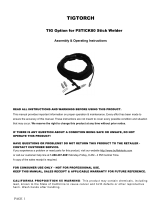
INPUT RECONNECT PROCEDURE
On multiple input voltage welders, be sure the
machine is connected per the following instructions
for the voltage being supplied to the welder.
Failure to follow these instructions can cause
immediate failure of components within the welder
and void machineʼs warranty.
-----------------------------------------------------------------------
Multiple voltage models are shipped connected
for the highest voltage. To change this connection
refer to the following instructions.
ELECTRIC SHOCK can kill.
• Turn the input power OFF at the dis-
connect switch or fuse box before
working on this equipment.
------------------------------------------------------------------------
For the lowest rated voltage connection (Refer to figure A.1):
1. Remove the sheet metal left side cover.
2. Disconnect lead H3 from the power switch and
insulate with the insulation from the H2 lead.
3. Connect lead H2 to the power switch where H3 was
connected.
4. Tighten connections.
5. Replace sheet metal cover and all screws
For the highest rated voltage connection (Refer to figure A.1):
The machine is normally shipped connected for the
highest rated voltage, however verify the following:
1. Remove the sheet metal left side cover.
2. Disconnect lead H2 from the power switch and
insulate with the insulation from the H3 lead.
3. Connect lead H3 to the line switch where H2 was
connected.
4. Tighten connections.
5. Replace sheet metal cover and all screws.
CONNECTIONS FOR TIG (GTAW) WELDING
TIG TORCH CONNECTION
Refer to Included Equipment in the Operation
Section of this manual for TIG welding equipment
which is included with the PRECISION TIG 225.
CAUTION
WARNING
FIGURE A.1 Reconnect Leads
INPUT LEADS INPUT LEADS
L1 & L2L1 & L2
LEAD H1LEAD H1
(DO NOT (DO NOT
REMOVE)REMOVE)
FOR LOWEST RATED VOLTAGEFOR LOWEST RATED VOLTAGE
: H2 CONNECTED: H2 CONNECTED
FOR HIGHEST RATED VOLTAGEFOR HIGHEST RATED VOLTAGE
: H3 CONNECTED: H3 CONNECTED
BACK VIEW OF LINE SWITCHBACK VIEW OF LINE SWITCH
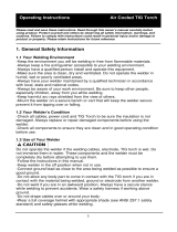
OUTPUT CONNECTIONS
FIGURE A.2 Location of Output Connections
ELECTRODE/GAS
OUTLET
RECEPTACLE
(TWIST-MATE)
WORK CABLE & CLAMP

A-6
INSTALLATION
PRECISION TIG 225
A-6
CONNECTIONS FOR TIG (GTAW) WELDING
TIG TORCH CONNECTION
Refer to Included Equipment in the Operation
Section of this manual for TIG welding equipment
which is included with the PRECISION TIG 225.
A PTA-17 Twist-Mate TIG welding torch with cable
and connector is supplied with the Ready-Pak Models
and available for other models (See Accessories
Section). Turn the Power Switch “OFF”. Connect the
torch cable Twist-Mate quick connect plug into the
Electrode/Gas Output Receptacle on the front of the
welder and turn it clockwise until it is tight. This is a
Twist-Mate quick connect terminal and also provides
the gas connection for the shielding gas to the torch.
To avoid receiving a high frequency shock, keep
the TIG torch and cables in good condition.
------------------------------------------------------------------------
WORK CABLE CONNECTION
A work cable with attached work clamp is factory con-
nected to the PRECISION TIG 225. To minimize high
frequency interference, refer to Input and Ground
and High Frequency Interference Protection sec-
tion of this manual for the proper procedure on
grounding the work clamp and work piece.
SHIELDING GAS CONNECTION
An adjustable gas pressure regulator with flow gage
and hose is supplied with the PRECISION TIG 225
Ready-Pak™ models and available separately for
other models (See Accessories Section). Obtain the
necessary inert shielding gas (usually argon). Connect
the cylinder of gas with the pressure regulator and
flow gage. Install the gas hose between the regulator
and gas inlet (located on the rear of the welder). The
gas inlet has a 5/16-18 right hand female thread;
CGA#032.
The availiable Under-Storage Cart features a low plat-
form that simplifies loading and unloading of gas cylin-
ders.
CYLINDER could explode
if damaged.
• Keep cylinder upright and chained
to a support.
• Keep cylinder away from areas
where it could be damaged.
• Never allow the torch to touch the cylinder.
• Keep cylinder away from live electrical circuits.
• Maximum inlet pressure 150 psi.
------------------------------------------------------------------------
A cylinder is loaded by leaning it slightly sideways and
rocking it up on the platform, being careful not to
allow the Under-Storage Cart to roll. Secure the
cylinder in place with the provided chain. Unload
by following these steps in reverse.
REMOTE CONTROL CONNECTION
A remote control receptacle is provided on the case
front of the welder for connecting a remote control to
to the machine. A Foot Amptrol™, foot activated
remote control, is included with the PRECISION TIG
225 Ready-Pak™ models and availiable separately
for other models. Refer to the Optional Accessories
Section of this manual for other available remote con-
trols.
CONNECTIONS FOR STICK (SMAW)
WELDING
STICK ELECTRODE CABLE AND WORK CABLE
CONNECTION
Refer to Field Installed Options in the Accessories
Section of this manual for STICK welding equipment
which is availiable for use with the PRECISION TIG
225. An electrode holder with Twist-Mate cable and
Twist-Mate connector are availiable separately for use
with the PRECISION TIG 225. (See Accessories
Section). Turn the Power Switch “OFF”. Connect
the Twist-Mate quick connect plug into the
Electrode/Gas Output Receptacle and turn it clock-
wise until it is tight. The work cable and work clamp
are factory connected.
WARNING
WARNING

B-1
OPERATION
PRECISION TIG 225
B-1
ELECTRIC SHOCK
can kill.
• Do not touch electrically live parts
or electrode with skin or wet cloth-
ing.
•
Insulate yourself from work and
ground.
• Always wear dry insulating gloves.
•
Read and follow “Electric Shock Warnings” in the
Safety section if welding must be performed under
electrically hazardous conditions such as welding in
wet areas or on or in the workpiece.
--------------------------------------------------------------------------------
FUMES AND GASES
can be dangerous.
• Keep your head out of fumes.
• Use ventilation or exhaust at the
arc, or both, to remove fumes and
gases from breathing zone and
general area.
------------------------------------------------------------------------
WELDING SPARKS can cause fire or
explosion
• Keep flammable material away.
• Do not weld on containers that
have held combustibles.
------------------------------------------------------------------------
ARC RAYS can burn.
• Wear eye, ear and body
protection.
------------------------------------------------------------------------
SAFETY PRECAUTIONS
Read and understand this entire section before oper-
ating the machine.
Observe additional Safety Guidelines detailed in
the beginning of this manual.
------------------------------------------------------------------------
WARNING
INPUT POWER
POSITIVE OUTPUT
NEGATIVE OUTPUT
DIRECT CURRENT
PROTECTIVE
GROUND
WARNING OR
CAUTION
DO NOT SWITCH
WHILE WELDING
GRAPHIC SYMBOLS THAT APPEAR ON
THIS MACHINE OR IN THIS MANUAL
SINGLE PHASE
TRANSFORMER AC AND
RECTIFIER DC POWER
SOURCE
OFF
ON

B-2
OPERATION
B-2
PRODUCT DESCRIPTION
The PRECISION TIG 225 is a member of our field
acclaimed Precision TIG family of industrial arc welding
power sources. Premium features include:
1. Precise constant current output.
2. Full range square wave AC/DC TIG (GTAW) welding.
3. Enhanced version of the patented Micro-Start II™
Technology for its lower Minimum(5 amps) to higher
Maximum (230 amps) output control range.
4. Built-in high frequency stabilization for DC TIG starting
and continuous AC TIG welding.
5. AC/DC Stick (SMAW capability.) A new undercarriage
(with gas bottle rack) is available for field installation, or is
included with an available Ready-Pak TIG Welding
Package. The Precision TIG patented convenient built-in
storage provisions for welding components and cable
management.
The PRECISION TIG 225 also provides advanced features
such as:
• Digital Meter
• Presettable control, adjustable Auto Balance™
• Fan As Needed (F.A.N.)
• Timers for fixed Preflow and variable Postflow shielding
gas.
• Built-in, easy to set single knob Pulse TIG control with a
"blinking" light to indicate the pulse frequency setting.
• Auto-Sense remote control selection.
• Tool-less Twist-Mate electrode cable connection.
• Built-in work clamp cable permanently attached.
Four models are available for 60Hz. with Domestic and
Canadian input voltages, as well as an International model
with 50/60Hz voltages.
An Auxiliary 115vac Receptacle with Circuit Breaker are
included on the back panel of the Precision TIG 225 models.
The Canadian (K2533-2) and International (K2534-1) mod-
els are rated 6 amps, while the 208/230/1/60 models
(K2533-1 and K2535-1/-2) are rated 20 amps (for use with
Lincolnʼs 115v SP and Power Mig models).
RECOMMENDED PROCESSES AND EQUIP-
MENT
RECOMMENDED PROCESSES
The PRECISION TIG 225 is recommended for the TIG
(GTAW) and Stick (SMAW) welding processes within its out-
put capacity range of 5 amps DC or AC to 225 amps
AC/DC. It is compatible with most Magnum TIG acces-
sories, as well as many industry standard items, such as
TIG torches (adapted for Twist-Mate), hoses, and water
coolers.
PROCESS LIMITATIONS
The Precision TIG machines are not recommended for arc
gouging due to its limited output capacity, and are also not
recommended for pipe thawing.
RECOMMENDED EQUIPMENT/INTERFACE
(See Installed Options in Accessories Section for
more details)
The PRECISION TIG 225 will be available as a basic
Machine (Only) and in two Factory-Configured Welding
Packages:
1. Machine(Only) (K2345-1)
2. Ready-Pak (K2347-1)
3. Ready-Pak w/Cart (K2347-2)
Basic module will also be available as with Domestic,
Canadian and International input voltages for user configu-
ration, with optional accessories.
Select Machine 208/230/1/60 Machine with NEMA 6-50P
Plug Cable and Receptacle (K2533-1)
460/575/1/60 Machine only with cable (K2533-2)
380/400/415/1/50/60 Machine only
with cable (K2534-1)
Torch Starter Kit Air Cooled System: Water Cooled System:
(Select one) TIG-Mate TIG-Mate 20
Torch Starter Kit* Torch Starter Kit*
Water Cooler Not Applicable 115V 50/60Hz
Cool-Arc 40*
Under-Storage K2348-(*)
Cart (Optional )
Optional Remote Arc Start Switch*
Trigger Device Foot Amptrol*
(Select one) Start Pedal Foot Amptrol*
Hand Amptrol*
*For “Part Numbers” or “K Numbers” see Accessories Section.
EQUIPMENT LIMITATIONS
The Precision TIG machines are protected from over loads
beyond the output ratings and duty cycles, per the
Specifications in the Installation Section, with Thermostat pro-
tection of the output power coils and rectifiers.
The PRECISION TIG 225 machine uses Twist-Mate output ter-
minals, therefore stud connection adapters (such as LECO.
S19257-series) cannot be used for torch connection.
If a PRECISION TIG 225 is powered from an engine generator
which doesnʼt have sufficient capacity, the AC Balance control
and the Output control will not provide full range of control.
WELDING CAPABILITY(Duty Cycle)
The PRECISION TIG 225 is rated at 225 amps, 29 volts, at
10% duty cycle on a ten minute basis. It is capable of higher
duty cycles at lower output currents. See rated output graph, on
specification sheet located in the Installation Section. If the duty
cycle is exceeded, a thermal protector will shut off the output
until the machine cools.
PRECISION TIG 225

B-3
OPERATION
B-3
CONTROL FUNCTIONALITY
1. POWER SWITCH – Input line switch turns input
power ON or OFF, as indicated by the on or off sta-
tus of the front panel digital display (See Item 6,
also see the following page for Power-Up
Sequence).
2. POLARITY SWITCH – The rotary power switch has
3-positions for DC+, AC and DC- selections for the
electrode output stud welding polarity.
• Do not switch the polarity switch
while welding or damage may result
to the machine.
------------------------------------------------------------------------
3. MODE SWITCH – The push button switch allows
selection of the two machine welding modes as
indicated by colored mode lights:
• STICK mode – Top position Red light.
• TIG mode – Bottom position Green light.
4. AC BALANCE CONTROL – The potentiometer
control permits AC TIG wave balance adjustment
from Max. Penetration (~80% negative wave) at full
CW rotation setting, to CCW rotation Max. Cleaning
(~60% positive wave), and includes:
• Auto Balance position indicated by the Green panel
light turning on. This feature automatically provides
the proper amount of cleaning and penetration for
normal AC TIG welding.
5. MAXIMUM OUTPUT CONTROL – Presets the out-
put welding current over the rated output range of
the machine:
• With a Remote Current Control (Amptrol) connect-
ed to the Remote Receptacle (See item 10), this
knob sets the Maximum output current level set
table with the remote Amptrol.
• For Pulse TIG (See Item 8) this knob sets the
Peak Pulse level, with the Remote Amptrol (if
used).
6. DIGITAL METER – A 3 digit LED meter is used to
display the preset output current level before weld-
ing, and actual output level while welding:
• A lit display indicates input power is turned on.
(See Item 1).
7. POST FLOW TIME – Sets the TIG mode shielding
gas post flow time over the range of about 1 to 30
seconds after the arc is shut off.
Note: Gas preflow time is fixed at 0.5 second only in
TIG mode, but no preflow time will occur if the arc is
restarted
during Post Flow time, since shielding gas
would not have stopped flowing.
PRECISION TIG 225
CONTROLS AND SETTINGS
All operator controls and adjustments are located on the front of the PRECISION TIG 225. Refer to Figure B.1
and corresponding explanations.
FIGURE B.1 - CONTROL PANEL
1. POWER SWITCH
2. POLARITY SWITCH
3. MODE SWITCH
4. AC BALANCE CONTROL
5. MAXIMUM
OUTPUT CONTROL (AMPS)
6. DIGITAL METERS
7. POST FLOW TIME
8. PULSE TIG CONTROL
9. THERMAL SHUTDOWN LIGHT
10. REMOTE RECEPTACLE
11. ELECTRODE/GAS OUTPUT
RECEPTACLE
12. WORK CABLE
13. REMOVABLE LIFT EYEBOLT
5
13
2
6
3
4
1
7
9
10
11
12
8
CAUTION

B-4
OPERATION
B-4
8. PULSE TIG CONTROL – The Pulse TIG feature
built into the PRECISION TIG 225 is simplified to
be a single knob control which sets the Pulse
Frequency over the peak pulses/sec. range of
about 0.1 to 20 pulses per second:
• Full CCW (min.) setting of the control knob shuts
off Pulse TIG (0.0 pps).
• Peak Pulse level is set by the Max. Output
Control and the Remote Amptrol (if used).
• Background Current level is typically optimized at
a fixed 50% of Peak Pulse level setting.
• Peak Pulse % On-time is typically optimized at a
fixed 50%.
A Green light "blinks" with each Peak Pulse to indi-
cate the Pulse TIG Control setting before
and dur-
ing welding.
9. THERMAL SHUTDOWN LIGHT This Yellow
LED panel light turns on if the machine output is
shutdown because internal overheating has
occurred, and turns off when cooled to reset.
10. REMOTE RECEPTACLE – Provides for connec-
tion of remote control and/or arc start switch only
in TIG Mode: (There is no remote output control
capability when stick welding).
• Plugging a remote current control (Amptrol) into
this receptacle automatically switches the output
control from the panel Max Output Control (See
Item 5) to the remote control.
• The connected remote control will then control
the output current between the Min. range of the
machine and the setting of the panel Max Output
Control.
• Switching Mode Switch (See Item 3) to Stick will
automatically disable
the connected remote con-
trol and switch the output control back to the Max
Output panel control.
11. ELECTRODE/GAS OUTPUT RECEPTACLE -
This quick connect Twist-Mate receptacle provides
electrical connection to the electrode holder and
cable for Stick welding and a combined electrical
and gas connection for the TIG torch when TIG
welding.
12. WORK CABLE - This 10ft.(3.05m) cable with
work clamp is factory connected to the welder and
its clamp is connected to the work piece to com-
plete the welding circuit. Refer to Machine
Grounding and High Frequency Interference
Protection in the Installation section of this manual
for the proper procedure on grounding the work
clamp and work piece to minimize high frequency
interference.
PRECISION TIG 225
POWER-UP SEQUENCE
When the Precision TIG 225 Power switch is initially
turned On , the following will be observed:
(Refer to this Section Controls and Settings Figure
B.1)
• The cooling fan will run for about 5 seconds.
• The previous (prior to Power Off) settings of Mode
and Maximum Output will be initiated.
• If in TIG Mode, the shielding gas solenoid valve will
be activated for the time set by the Post Flow Time
control.

B-5
OPERATION
B-5
CASE REAR COMPONENTS
1. INPUT CABLE– This #6-3 (208/230V) or #12-3
(380V and higher) heavy duty cable with cable
clamp is factory installed on all models. The
Domestic models (208/230V) also are equipped
with a NEMA 6-50P plug.
2. GAS INPUT CONNECTOR – This is a 5/8-18 right-
hand thread female fitting for connection of input
gas supply.
3. COOLING AIR VENTS – Air is drawn in through
the upper vents and exhausted out through the
lower vents. The louver baffle steers exhaust air
down and prevents it from re-entering the upper
vents.
4. MACHINE RATING PLATE
5. RECEPTACLE AND CIRCUIT BREAKER-115vac
auxiliary NEMA 6-20R .
PRECISION TIG 225
FIGURE B.2
1
5
4
2
3

B-6
OPERATION
B-6
PRECISION TIG 225
OPERATING STEPS
WELDING IN TIG MODE
1. Connect the TIG torch and cable Twist-Mate quick
connect plug to the Electrode/Gas output recepta-
cle. This receptacle also contains an integral gas
connection for the torch. Connect the work clamp to
the work piece.
2. Set the TIG/STICK switch to “TIG”.
3. Set the Polarity Switch to DC- for welding steel or
stainless steel; or to AC for welding aluminum.
4. Connect the Foot Amptrol to the Remote Control
Connector.
5. Turn on the cylinder gas valve and adjust the flow
regulator to obtain desired flow.
6. Turn the power switch to “ON”. NOTE: There will be
a 15 second gas flow when the power is turned on.
7. Preset the Output Control on the control panel to
the maximum desired amps, as read on the digital
meter.
8. Depress the Foot Amptrol to energize the torch and
establish an an arc with the work piece. The digital
meter reads the actual amps while welding.
NOTE: When the TIG/STICK switch is set to “TIG”,
depressing the remote control will start a 0.5 second
gas pre-flow before energizing the TIG torch. When
the remote control is released the TIG torch is de-
energized and gas flow will continue for the time set
by the Post Flow Time control. When the polarity
switch is set to DC, the TIG Arc Starter will turn on
and off automatically to start and stabilize the arc. In
AC the TIG Arc Starter will turn on with the output and
remain on continuously until the remote control is
released.
PULSE TIG CONTROL
Use this knob to set the frequency or the number of
pulses per second(pps), from 0.1pps to 20pps.
• This setting adjusts heat output and bead shape for
travel speed. Thinner plate that is welded with faster
travel speed will require higher frequency than thick-
er plate with slower travel speed. 2-3pps is a typical
starting point.

B-7
OPERATION
B-7
REMOTE CONTROL OPERATION
A Foot Amptrol ™is included with the PRECISION
TIG 225 Ready-Pak models and availiable for other
models (See Accessories Section) for remote current
control while TIG welding. An optional Hand Amptrol
may also be used. An optional Arc Start Switch may
be used to start and stop the welding if no remote
control of the current is desired. Refer to the
Accessories Section of this manual.
Both the Hand and Foot Amptrol work in a similar
manner. For simplicity, the following explanation will
refer only to “Amptrols”, meaning both Foot and Hand
models. The term “minimum” refers to a foot pedal in
the “up” position, as it would be with no foot pressure,
or a Hand Amptrol in the relaxed position, with no
thumb pressure.
“Maximum” refers to a fully depressed Foot Amptrol,or
a fully extended Hand Amptrol.
When the welder is in TIG modes activating the
Amptrol energizes the electrode terminal and varies
the output welding current from its minimum value of 5
Amp (DC) or (AC), to the maximum value set by the
Current Control on the control panel. This helps elimi-
nate accidental high current damage to the work piece
and/or tungsten, and provides a fine control of the cur-
rent. When the welder is in the stick mode a remote
control has no effect and is not used.
It is important to note that, in some cases, the tung-
sten will not start an arc at the minimum current
because the tungsten may be too large or cold. To
start an arc reliably, it is important to depress the
Amptrol far enough so that the machine output current
is near the tungsten operating range. For example, a
3/32” tungsten may be used on DC- to weld over the
full range of the machine.
To start the arc, the operator may have to turn the cur-
rent control up and depress the Amptrol approximately
1/4 of the way down. Depressing the Amptrol to its
minimum position may not start the arc. Also if the
current control is set too low, the arc may not start. In
most cases, a large or cold tungsten will not readily
establish an arc at low currents. This is normal. In
Direct Current mode the PRECISION TIG 225 will
start a 3/32”, 2% thoriated tungsten electrode at 15
amperes provided the electrode tip is properly ground-
ed and not contaminated.
BENEFITS OF THE PRECISION TIG 225 DESIGN
In AC TIG welding of aluminum, the positive portion of
the AC wave provides cleaning (removal of aluminum
oxide) of the work piece. This is desirable on materials
with a heavy oxide coating. However the positive por-
tion may also cause the electrode to overheat at high
currents causing “tungsten spitting”. The negative por-
tion of the AC wave offers no cleaning action but con-
centrates more heat on the work.
The AC waveform of the PRECISION TIG 225 opti-
mizes cleaning and heating of the work. The result is
the capability to weld through the complete range in
AC TIG or DC- TIG requiring only one electrode, a
3/32” 2% thoriated tungsten.
PRECISION TIG 225

B-8
OPERATION
B-8
WELDING IN STICK MODE
1. Put the electrode holder and cable quick connect
plug into the electrode output receptacle. Turn
clockwise until tight. Connect the work clamp to the
work piece.
2. Set the TIG/STICK switch to “STICK”.
3. Set the Polarity Switch to the weld mode desired for
the type of electrode being used (most commonly
DC+).
4. Place the electrode in the electrode holder.
• In Stick Mode the output terminal
and electrode will be electrically hot
whenever the power switch is
turned on.
-----------------------------------------------------------------------
5. Turn the power switch to “ON”.
6. Adjust the Current Control to the desired amps.
7. Strike an arc and weld.
NOTE: When the TIG/STICK switch is set to “STICK”
the output is always on when the power switch is on.
A remote control has no effect on the welding current
and the gas flow and high frequency TIG arc starter
are disabled.
PRECISION TIG 225
RECOMMENDED ELECTRODE AMPERAGE RANGES - PRECISION TIG 225
The PRECISION TIG 225 is rated from 5-225 Amps.
SMAW Process
Welding Amp Range for Stick Electrode Size
ELECTRODE TYPE POLARITY 3/32" 1/8" 5/32"
Fleetweld 5P, Fleetweld 5P+ E6010
DC+ 40 - 70 75 - 130 90 - 175
Fleetweld 180 E6011 DC+ 40 - 80 55 - 110 105 - 135
Fleetweld 37 E6013 DC+ 70 - 95 100 - 135 145 - 180
Fleetweld 47 E7014 DC- 75 - 95 100 - 145 135 - 200
Excalibur E7018 DC+ 85 - 110 110 - 160 130 - 200
Blue Max Stainless DC+ 40 - 80 75 - 110 95 - 150
Red Baron Stainless DC+ 40 - 70 60 - 100 90 - 140
Mild steel procedures are based on recommended procedures listed in C2.10 8/94 and the maximum rating of the PRECISION TIG 225
Blue Max procedures are based on C6.1 6/95
Red Baron Procedure are based on ES-503 10/93
GTAW Process
Electrode Polarity DC- AC Approximate Argon
Electrode Tip Preparation
Sharpened Balled Gas Flow Rate
Electrode Type
EWZr C.F.H. (l/min.)
EWTh-1, EWCe-2
EWTh-1, EWTh-2
EWTh-2, EWLa-1
EWP EWCe-2, EWLa-1 Stainless
Tungsten Size (in.) EWG EWG Aluminum Steel
.010 Up to 15 A. Up to 10 A. Up to 15 A. 3-8 (2-4) 3-8 (2-4)
.020 Up to 15 A. Up to 15 A. Up to 20 A. 5-10 (3-5) 5-10 (3-5)
.040 Up to 80 A. Up to 40 A. Up to 60 A. 5-10 (3-5) 5-10 (3-5)
1/16 Up to 150 A. Up to 100 A. Up to 130 A. 5-10 (3-5) 9-13 (4-6)
3/32 Up to MAX. A. Up to 160 A. Up to MAX. A. 13-17 (6-8) 11-15 (5-7)
1/8 X Up to MAX. A. X 15-23 (7-11) 11-15 (5-7)
Tungsten electrodes are classified as follows by the American Welding Society (AWS):
Pure ..................................EWP........green TRI-MIX OF ELEMENTS.............EWG.........gray
+1% Thoria .......................EWTh-1 ...yellow
+2% Thoria .......................EWTh-2 ...red
+2% Ceria.........................EWCe-2...orange
+1.5% Lanthana ...............EWLa-1 ...black
+0.15 to 0.40% Zirconia....EWZr.......brown
Ceriated Tungsten is now widely accepted as a substitute for 2% Thoriated Tungsten in AC and DC applications.
WARNING
/