Page is loading ...

© LINDY ELECTRONICS LIMITED & LINDY-ELEKTRONIK GMBH - FIRST EDITION (MAY 2004)
For Home and Office Use
Tested to Comply with
FCC Standards
CPU Switch LITE USB 2.0
User Manual
English
Benutzerhandbuch
Deutsch
Manuel Utilisateur
Français
Manuale d’uso
Italiano
CPU Switch LITE USB 2.0
2 Port, No. 32825
CPU Switch LITE USB 2.0
4 Port, No. 32826
www.LINDY.com

Content
This manual contains the following parts:
A Quick Start Instructions
B English Manual
C German Manual /
Deutsches Benutzerhandbuch
D French Manual /
Manuel en français
E Italian Manual /
Manuale in italiano
F Technical Data and Compliance Statement

Quick Start Instructions
• Make sure all the devices to be connected to the CPU
Switch LITE USB 2.0 are turned off.
• Connect the CPU Switch LITE USB 2.0 to the computers
keyboards, monitors and mice.
• USB devices are hot pluggable. Please always allow the
connected computers to install their drivers completely
before switching to the next port!
• Switch the monitor on first, then the computers.
• Do not
switch channels during boot up of the connected
computers.
• For operation you can change the computer ports by
pressing the hotkey from your keyboard. To learn about
the advanced hotkey switching possibilities of this
switch please read the manual.
Detailed information can be found under the Installation
and Operation Sections of this manual.

English Manual ENG 1
Overview
The LINDY CPU Switch LITE USB 2.0 combines control of up to 4 computers from one PS/2 or
USB keyboard, mouse and monitor, with the facility to share USB 2.0/1.1 devices.
The unit requires no software installation. Any modern USB 2.0 enabled operating system will
support both the switch and the USB hub. Simply connect the cables and turn on the devices!
CPU Switch function
With the CPU Switch you can eliminate the cost of additional accessories, save valuable desk
space and remove all of the problems associated with using multiple keyboards, monitors and
mice. The CPU Switch LITE USB 2.0 provides flexible switching between the connected
computers, using either the built-in button or PC keyboard hotkeys.
Note: Keyboard hotkey switching is not supported when using USB Mac/Sun keyboards!
USB Share function
When using a PS/2 PC keyboard and mouse, the USB Share function allows USB devices to be
switched independently from the ‘PS/2 + VGA’ part of the CPU Switch. This means you can
switch keyboard, monitor and mouse from one computer whilst keeping the USB devices
connected to the other. For example, you can print to a USB printer from PC 1, and then switch
your keyboard, monitor and mouse to PC 2, leaving the USB printer still connected to PC 1.
Restrictions when using 4D/5D and wireless mice, and extended multimedia keyboards
The CPU Switch LITE USB 2.0 interprets and converts PS/2 to USB signals and then sends
them via the USB bus to the attached computers. The official PS/2 to USB Conversion Standard
does not define any proprietary function for mice with more than 3 buttons and 1 wheel. Also, it
does not define a conversion standard for the additional keys of extended multimedia
keyboards. Furthermore, there is no conversion standard for special wireless functions like
battery status monitoring and RF device ID identification etc. The CPU Switch LITE USB 2.0 is
not able to convert these special functions from PS/2 to USB, indeed these functions will not
work with any current KVM switch which features PS/2 to USB conversion!
Note: If you need these extra functions you can use USB mice and keyboards – but you will
lose the advanced keyboard hotkey switching features, and some of the USB Share
functionality!

English Manual ENG 2
Features
• USB 2.0 specification compliant, backwards compatible with USB 1.1
• Supports EHCI, UHCI, OHCI USB interface
• Compatible with any widely used USB enabled operating system
• Embedded USB hub to share different USB peripherals between all computers
• LED port display for easy status monitoring
• Beep sound when switching between computers
• Auto scan function
• Supports monitor resolution of up to 2048 x 1536 and high bandwidth over 250MHz
• Supports DDC, DDC2, DDC2B
• Bus powered (if used with self powered or low power USB devices) or self powered
(requires power supply, not included)
Package Contents
• LINDY CPU Switch LITE USB 2.0, 2 Port or 4 Port model
• 2 or 4 KVM combo cables USB 2.0 + VGA (depending on model)
• This manual
Installation
1. Before installation, please switch off all of the devices.
2. Connect the computers to the CPU Switch LITE USB 2.0 using the supplied 2m KVM
USB 2.0 + VGA cables.
3. Connect either a PS/2 or USB keyboard and mouse, and a monitor to the sockets on the
LINDY CPU Switch LITE USB 2.0.
4. The console port of the CPU Switch LITE USB 2.0 supports PS/2 or USB keyboards and
mice, in any combination.
5. You can use a (self powered) USB 2.0 hub to connect extra USB devices.
Power requirements / USB bus powered operation
The CPU Switch LITE USB 2.0 can draw its power from either the connected computers or from
an optional external 5V DC power supply (regulated voltage - an old style heavy power supply
with a transformer may damage the connected USB devices and computers).
When using the CPU Switch LITE 2.0 in USB bus power mode (without the optional power
supply), you can connect low power USB devices (driving up to 100mA power from the USB
bus), or self powered USB devices only!
Tip: You can find the power requirement of any USB device which is connected to your PC by
launching –
Windows Device Manager ►USB Controller ►USB Hubs ►Properties ►Power
and then checking the ‘Power Required’ in the ‘Attached Devices’ box.

English Manual ENG 3
Scroll
Lock
For bus powered operation with low power USB devices attached, at least two computers
should be connected, and be powered up. Bus powered operation also depends on the number
of USB devices attached, and how much current they draw from the USB bus.
Alternatively, you can attach a regulated 5V DC power supply to the CPU Switch LITE USB 2.0
or you can connect your USB devices via a self powered USB 2.0 hub.
Operation
To switch between the connected computers press the button on the CPU Switch LITE USB 2.0
or use a hotkey from your PC keyboard.
Hotkey control
(PC USB & PS/2 PC Keyboards only!)
To send commands to the CPU Switch the key must be pressed twice within 2
seconds. This puts the CPU Switch into command mode. You will hear a beep for confirmation.
Any further key presses must follow within another two seconds. If not, the CPU Switch exits
from command mode and any further key presses are transferred to the selected computer.
Note: Hotkey switching is available when using either a PS/2 or USB PC keyboard only! It is
not available when using Mac and Sun keyboards! Advanced Hotkey control is only available
when using a PS/2 PC keyboard!
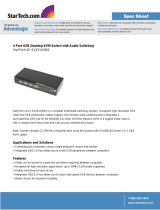
USB PC Keyboard Controls
To switch USB Keyboard, Mouse, Monitor & USB devices (together) between computers
Within 2 seconds
+ + = Previous Channel
or
+ + = Next Channel
Note:
This is the only Hotkey control available when using USB PC Keyboards. For Advanced
Hotkey control you must use a PS/2 PC keyboard!
Advanced Hotkey Control (PS/2 PC Keyboards only!)
To switch PS/2 Keyboard/Mouse, Monitor & USB devices (together) between computers
Within 2 seconds
+ + = Previous Channel
or
+ + = Next Channel
Select PC port :
+ + = To select PC1 ~ PC2 or ~ PC4 directly
Scroll
Lock
Scroll
Lock
↑
↓
Scroll
Lock
Scroll
Lock
Port No.
1…2/4
Scroll
Lock
Scroll
Lock
↑
↓

English Manual ENG 4
To switch PS/2 Keyboard/Mouse & Monitor between computers (not USB devices)
Within 2 seconds
+ + + = Previous Channel
or
+ + + = Next Channel
Select PC port :
+ + + = To select PC1 ~ PC2 or ~ PC4
directly
To switch USB devices only between computers
Within 2 seconds
+ + + = Previous Channel
or
+ + + = Next Channel
Select PC port :
+ + + = To select PC1 ~ PC2 or ~ PC4
directly
To change Auto Scan Mode and Scan Interval
+ + = Auto Scan. To get out of Auto Scan Mode,
Press any key or SPACE bar.
OR
+ + = + any Number between 0-9 with:
1 = 10 seconds, 2 = 20 seconds, 3 = 30 seconds, 4 = 40 seconds, 5 = 50 seconds,
6 = 60 seconds, 7 = 70 seconds, 8 = 80 seconds, 9 = 90 seconds, 0 = 100 seconds
The default Auto Scan Interval is 5 seconds at power on.
The first command switches the console only into Scan mode. USB devices are not switched. It
works only when two computers are powered on at the same time.
Exit Auto Scan Mode by pressing any key
To check beep function
+ + = Beeper , Check beep function is OK
Scroll
Lock
Scroll
Lock
↑
↓
Scroll
Lock
Scroll
Lock
Port No.
1…2/4
END
END
Scroll
Lock
Scroll
Lock
↑
↓
Scroll
Lock
Scroll
Lock
Port No.
1…2/4
Home
Home
Scroll
Lock
Scroll
Lock
S
Scroll
Lock
Scroll
Lock
S
Scroll
Lock
Scroll
Lock
B

English Manual ENG 5
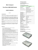
Keyboard Mapping for Mac & Sun Computers
The following diagram shows the Hotkey combinations that emulate Mac and Sun keyboard
commands.
Note: This feature is only available on a PS/2 PC keyboard attached to the CPU Switch LITE
USB 2.0. It is not available when using a USB keyboard!
Example: Left Windows Key = L_Win
Sun Microsystems
Keyboard
Stop
Props
Compose
Front
Open
Find
Again
Undo
Copy
Paste
Cut
Help
Power
Mute
V_DN
V_UP
Windows ps2
Keyboard
L_Win & L_Alt
L_Win & L_Ctrl
L_Win & L_Shift
L_Win & F1
L_Win & F2
L_Win & F3
L_Win & F4
L_Win & F5
L_Win & F6
L_Win & F7
L_Win & F8
L_Win & F11
L_Win & F12
L_Win & "1"
L_Win & "2"
L_Win & "3"
Windows Key
Alt
Print Screen
Scroll Lock
Pause Break
Mac OS
Power
Apple Key
Option
F13
F14
F15
LED Port Display
Two colour LED’s (orange and green) are used to display the status of each port:
1. When a single port LED is
orange
and no other LED is lit, the console (keyboard, mouse
and monitor) and USB hub are both connected to this port.
2. If the console and USB hub are connected to different computer ports, the LED of the port
linked to the
console
will light up
orange
, and the LED of the port connected to the
USB
hub
will light up
green
.
3. If you select a port to which no computer is connected, or to which the attached computer is
shut down, the selected port LED will light up
orange
and flash on and off.

English Manual ENG 6
Troubleshooting
If you experience any problems, first ensure that all cables are well seated and that both the
mouse and keyboard have been correctly installed in each of the connected computers
operating systems before connecting to the CPU Switch Lite USB 2.0.
Tip: To avoid confusion label the cables with the number of each connected computer!
PC Computers
• Error Message: Keyboard or mouse are not found/not recognised during Boot-up.
When connecting a PS/2 keyboard to the CPU Switch LITE USB 2.0’s PS/2 port,
the computer fails to boot because of a keyboard error! The PC’s BIOS (Basic Input
Output System) may need to be upgraded to so that it accepts USB to PS/2 conversion
(normally most modern BIOS will support this). Check your PC/motherboard
manufacturer’s web site for the latest BIOS version.
• The keyboard or mouse is not working or not compatible with the PC! Please
make sure the keyboard and/or mouse works correctly when plugged directly into each
of the computers. If the problem persists, please try another keyboard or mouse.
(Please also regard the restriction remarks on page 1 of this manual).
• Mouse not working in Auto Scan mode! Press any key on the keyboard, or the button
on the CPU Switch to return it to standard mode and then try the keyboard or mouse
again.
• About Auto Scan mode. When the CPU Switch LITE USB is in Auto Scan mode, each
computers display is output to the monitor one by one. The USB Hub is not switched in
auto scan mode! When you see the display of the computer you want to control, simply
press a key and the console connects to that port.
• What is the maximum recommended VGA cable length? The maximum
recommended VGA cable length is 5m (20 feet).
• What are the maximum recommended keyboard and mouse cable lengths? The
recommended maximum keyboard and/or mouse cable length is 3m (10 feet).
• What is the maximum recommended USB cable length? The maximum USB cable
length is 5m (20 foot). If you experience problems using longer cable lengths, please
use a USB Active Extension Cable. Please always regard the maximum USB cable
segment length of 5m, and the maximum number of USB 2.0/1.1 segments.
• When switching the USB Hub from one computer to another and there are many
USB devices attached or shared, it will take about 10 seconds for all USB devices to
be initialised.

English Manual ENG 7
Sun Microsystems Computers
If you use a Sun Microsystems computer with the CPU Switch LITE USB 2.0, you need to
switch the console to the port connected to the Sun Microsystems computer
before
you boot
up. After you finish booting the Sun, you can switch the console to the other computer ports.
If you connect a USB PC keyboard to a USB hub port and a Sun Microsystems computer is
connected to the CPU Switch LITE USB 2.0, then the keyboard will not work correctly as there
is no Sun-to-PC keyboard mapping available. Sun-to-PC keyboard mapping is only available
when using a PS/2 PC keyboard. You can connect a Sun USB keyboard to one of the USB hub
ports.
Note: Please note that most Hotkey switching functions are available from PS/2 PC keyboards
only!
Mac Computers
If you connect a USB PC keyboard to a USB hub port and a Mac is connected to the CPU
Switch LITE USB 2.0, then the keyboard will not work correctly as there is no Mac-to-PC
keyboard mapping available. Mac-to-PC keyboard mapping is only available when using a PS/2
keyboard. You can connect a Mac keyboard to one of the USB hub ports.
Note:
All features, specifications and hotkey functions may be subject to chang
e
when newer firmware revisions are used in future versions of this product.
Version 1.0 February 2004

Technical Specifications, Radio Frequency Energy, Certifications
© LINDY ELECTRONICS LIMITED & LINDY-ELEKTRONIK GMBH - FIRST EDITION (MAY 2004)
For Home and Office Use
Tested to Comply with
FCC Standards
Model No. 32825 : 2 Port CPU Switch LITE USB 2.0 32826 : 4 Port CPU Switch LITE USB 2.0
Computer Ports 2 4
Console Port 1 : VGA + (2x PS/2) and/or via USB device ports 1 : VGA + (2x PS/2) and/or via USB device ports
Computer Port Connector
USB Type B receptacle
VGA HD 15pin Female
USB Type B receptacle
VGA HD 15pin Female
Console Port Connector PS/2 Keyboard mini-Din 6 pin Female (or via USB)
PS/2 Mouse mini-Din 6 pin Female (or via USB)
VGA HDDB 15pin Female
PS/2 Keyboard mini-Din 6 pin Female (or via USB)
PS/2 Mouse mini-Din 6 pin Female (or via USB)
VGA HDDB 15pin Female
Computer selection PS/2 PC Hotkey or Button on the CPU Switch PS/2 PC Hotkey or Button on the CPU Switch
LED 2 4
Scan Intervals 5,10,20,30,40,50,60,70,80,90,100 sec. 5,10,20,30,40,50,60,70,80,90,100 sec
Keyboard Conversion PS/2 to USB PS/2 to USB
Mouse Conversion PS/2 to USB PS/2 to USB
VGA Resolution 2048X1536 2048X1536
Bandwidth 400MHz 400MHz
Power Type Bus Power (Optional to Self power mode) Bus Power (Optional to Self power mode)
Power Adapter Switching Power Optional ( DC5V, 2A ) Switching Power Optional (DC5V, 2.5A)
Operation Temperature 0~50 0~50
Storage Temperature -20 ~ 60 -20 ~ 60
Humidity 0~90%, Non-Condensing 0~90%, Non-Condensing
Size Mini Desktop Desktop
Dimension (mm) 118(L)X87(W)X34(H) 186(L)X92(W)X34(H)
Weight (g) 174 293
Shielded cables must be used with this equipment to maintain compliance with radio
frequency energy emission regulations and ensure a suitably high level of immunity to
electromagnetic
disturbances.
FCC Warning
This equipment has been tested and found to comply with the limits for a Class B Digital device,
pursuant to part 15 of the FCC Rules. These limits are designed to provide reasonable protection
against harmful interference in a residential installation. This equipment generates, uses, and can
radiate radio frequency energy and, if not installed and used in accordance with the instructions, may
cause harmful interference to radio communications. However, there is no guarantee that interference
will not occur in a particular installation. If this equipment does cause harmful interference to radio or
television reception, which can be determined by turning the equipment off and on, the user is
encouraged to try to correct the interference by one or more of the following measures:
Reorient or relocate the receiving antenna
Increase the separation between the equipment and receiver
Connect the equipment into an outlet on a circuit different from that to which the receiver is
connected
Consult the dealer or an experienced technician for help
You are cautioned that changes or modifications not expressly approved by the party responsible for
compliance could void your authority to operate the equipment.
This device complies with part 15 of the FCC Rules.
Operation is subject to the following two conditions:
1. This device may not cause harmful interference, and
2. This device must accept any interference received, including interference that may cause undesired
operation
/