Page is loading ...

Transition Networks
CPSMC0800-100
8-Slot PointSystem™ Chassis
User’s Guide
(revision A)

2
CPSMC0800-100 PointSystem™ Chassis
Tech Support: 7am-6pm CST (GMT -6:00) 1-800-260-1312 International: 00-1-952-941-7600
Compliance Information
UL Listed
C-UL Listed (Canada)
CISPR22/EN55022 Class A + EN55024
CE Mark
FCC Regulations
This equipment has been tested and found to comply with the limits for a class A digital device, pursuant to part 15 of
the FCC rules. These limits are designed to provide reasonable protection against harmful interference when the equip-
ment is operated in a commercial environment. This equipment generates, uses, and can radiate radio frequency ener-
gy and, if not installed and used in accordance with the instruction manual, may cause harmful interference to radio
communications. Operation of this equipment in a residential area is likely to cause harmful interference, in which case
the user will be required to correct the interference at the user’s own expense.
Canadian Regulations
This digital apparatus does not exceed the Class A limits for radio noise for digital apparatus set out on the radio inter-
ference regulations of the Canadian Department of Communications.
Le présent appareil numérique n'émet pas de bruits radioélectriques dépassant les limites applicables aux appareils
numériques de la class A & B prescrites dans le Règlement sur le brouillage radioélectrique édicté par le ministère des
Communications du Canada.
European Regulations
Warning
This is a Class A product. In a domestic environment this product may cause radio interference in which case the user
may be required to take adequate measures.
Achtung !
Dieses ist ein Gerät der Funkstörgrenzwertklasse A. In Wohnbereichen können bei Betrieb dieses Gerätes
Rundfunkstörungen auftreten, in weichen Fällen der Benutzer für entsprechende Gegenmaßnahmen werantwortlich ist.
Attention !
Ceci est un produit de Classe A. Dans un environment domestique, ce produit risque de créer des interférences
radioélectriques, il appartiendra alors à l’utilsateur de prende les measures spécifiques appropriées
Trademark Notice
All trademarks and registered trademarks are the property of their respective owners.
Copyright Restrictions
© 2003 Transition Networks.
All rights reserved. No part of this work may be reproduced or used in any form or by any means – graphic, electron-
ic, or mechanical – without written permission from Transition Networks.
Printed in the U.S.A.
33270.A
CAUTION: THE RJ CONNECTORS ON THE INDIVIDUAL MEDIA CONVERTER SLIDE-IN-MODULES
ARE NOT INTENDED FOR CONNECTION TO THE PUBLIC TELEPHONE NETWORK. Failure to observe
this caution could result in damage to the public telephone network.
Der Anschluss dieses Gerätes an ein öffentlickes Telekommunikationsnetz in den EG-Mitgliedstaaten
verstösst gegen die jeweligen einzelstaatlichen Gesetze zur Anwendung der Richtlinie 91/263/EWG zur Angleichung
der Rechtsvorschriften der Mitgliedstaaten über Telekommunikationsendeinrichtungen einschliesslich der gegenseitigen
Anerkennung ihrer Konformität.

3
CPSMC0800-100 PointSystem™ Chassis
Table of Contents
1 Introduction . . . . . . . . . . . . . . . . . . . . . . . . . . . . . . . . . . . . . . .4
1.1 Description . . . . . . . . . . . . . . . . . . . . . . . . . . . . . . . . . . . . . . . . . .4
1.2 Unpacking the CPSMC0800-100 Equipment . . . . . . . . . . . . . . . . .5
2 Slide-in-Modules . . . . . . . . . . . . . . . . . . . . . . . . . . . . . . . . . . .6
2.1 Media Converter Slide-in-Modules . . . . . . . . . . . . . . . . . . . . . . . . .6
2.1.1 Calculating Power Consumption . . . . . . . . . . . . . . . . . . . . . . . . . . . . . .6
2.1.2 Installing Media Converter Slide-in-Modules . . . . . . . . . . . . . . . . . . . . .7
2.1.3 Replacing Media Converter Slide-in-Modules . . . . . . . . . . . . . . . . . . . . .8
2.2 Managment Modules . . . . . . . . . . . . . . . . . . . . . . . . . . . . . . . . . . .9
2.2.1 Three Types of Management Modules . . . . . . . . . . . . . . . . . . . . . . . . . .9
2.2.2 Installing the Management Modules . . . . . . . . . . . . . . . . . . . . . . . . . . .10
2.2.3 Replacing the Management Modules . . . . . . . . . . . . . . . . . . . . . . . . . .11
3 Powering the CPSMC0800-100 . . . . . . . . . . . . . . . . . . . . . . .12
3.1 Primary Power Supply . . . . . . . . . . . . . . . . . . . . . . . . . . . . . . . . .12
3.2 Auxilliary Power Supply . . . . . . . . . . . . . . . . . . . . . . . . . . . . . . . .13
4 CPSMC0800-100 Chassis . . . . . . . . . . . . . . . . . . . . . . . . . . . .14
4.1 Installing the CPSMC0800-100 Chassis . . . . . . . . . . . . . . . . . . . .14
4.1.1 Standard 19-Inch Rack Installation . . . . . . . . . . . . . . . . . . . . . . . . . . . .14
4.1.2 Table-Top Installation . . . . . . . . . . . . . . . . . . . . . . . . . . . . . . . . . . . . . .15
4.2 Cascade Option . . . . . . . . . . . . . . . . . . . . . . . . . . . . . . . . . . . . . .16
4.3 Connecting the Slide-in-Modules to the Network . . . . . . . . . . . . .17
4.4 Operation . . . . . . . . . . . . . . . . . . . . . . . . . . . . . . . . . . . . . . . . . . .18
5 SNMP Agent in the Management Module . . . . . . . . . . . . . . .19
5.1 SNMP Hardware Connections . . . . . . . . . . . . . . . . . . . . . . . . . . .19
5.2 SNMP Software . . . . . . . . . . . . . . . . . . . . . . . . . . . . . . . . . . . . . .20
6 Fault Isolation and Correction . . . . . . . . . . . . . . . . . . . . . . . .21
Technical Specifications . . . . . . . . . . . . . . . . . . . . . . . . . . . . . . . . . . . . .22
Cable Specifications . . . . . . . . . . . . . . . . . . . . . . . . . . . . . . . . . . . . . . . .23
Contact Us . . . . . . . . . . . . . . . . . . . . . . . . . . . . . . . . . . . . . . . . . . . . . . .24
Warranty . . . . . . . . . . . . . . . . . . . . . . . . . . . . . . . . . . . . . . . . . . . . . . . . .25
Tech Support: 7am-6pm CST (GMT -6:00) 1-800-260-1312 International: 00-1-952-941-7600

4
CPSMC0800-100 PointSystem™ Chassis
introduction
1 Introduction
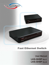
1.1 Description
The Transition Networks PointSystem™ CPSMC0800-100 is a 19-inch, rack-mount-
able chassis for selected Transition Networks Media Converter Slide-In-Modules.
The CPSMC0800-100 allows the network administrator to connect various copper
and fiber-optic network media over protocols that include Ethernet™, Fast
Ethernet™, DS3/E3, and OC-12. The CPSMC0800-100 provides installation space
for up to eight (8) single-slot or four (4) dual-slot Media Converter Slide-in-Modules
in the front of the unit.
The CPSMC0800-100 also comes equipped with an AC or DC power supply. An
optional AC or DC power supply with Instant Fail Over operation is also available.
The primary power supply is accessed through the Power Inlet on the front panel,
while auxilliary power is accessed through the Auxilliary Power Inlet, located on the
back panel.
Four fans, two for the power supplies and two for the Slide-In-Modules, help remove
heat from the chassis.
With installed PointSystem™ Management Module(s) (TN part number CPSMM-
120, -200, or -210), the CPSMC0800-100 can be managed and monitored via:
• An SNMP application such as Transition Networks FocalPoint™ management
software installed at a remote Network Management Station (NMS).
• A remote Web browser.
• A command-line interface (CLI) at an attached terminal.
• A command-line-interface (CLI) at a remote Telnet connection.
The management features include:
• Power control (slot on, slot off, in rush limit) for each individual slot.
• Internal temperature monitor.
• Fan failure monitor.
• Chassis power consumption monitor.
• Power supply type identification.
• Power supply condition monitor.
• Fail-over power detection.
The Management Modules also make it possible to control up to eight (8) cascaded
CPSMC0800-100 chassis, which can accomodate up to 55 installed Media
Converter Slide-in-Modules.
Tech Support: 7am-6pm CST (GMT -6:00) 1-800-260-1312 International: 00-1-952-941-7600
10BASE-T
INPORT
MCCM10
MGMT MASTER
OUTPORT
12C
12C-1TERM
INIT
RX
TX
LNK
PWR
RESET
DB-9
CFETF110
SPD
PWR
FRX
CRX
FLNK
CLNK
10/100TX
RX
TX
10/100SX
LKS
PWR
LKM
Multimode
Singlemode
TX
RX
TX
RX
CFETF110
SPD
PWR
FRX
CRX
FLNK
CLNK
10/100TX
RX
TX
10/100SX
LKS
PWR
LKM
Multimode
Singlemode
TX
RX
TX
RX
CPSMC-0800
8-Slot Chassis
Mpls, MN 55344
Mpls, MN 55344
Input Power:
Input Power:
110-240 VAC
110-240 VAC
1.6A max. (60W max)
1.6A max. (60W max)
50/60 Hz
50/60 Hz
Management Module Installed Slide-In-Module Open Slot Power Inlet
Mpls, MN 55344
Input Power:
110-240 VAC
1.6A max. (60W max)
50/60 Hz
Auxilliary Power Inlet

5
CPSMC0800-100 PointSystem™ Chassis
introduction
2.1 Unpacking the CPSMC0800-100 Equipment
Use the following list to verify the shipment:
Item Part Number
8-Slot chassis with AC power supply CPSMC0800-100
8-Slot chassis with DC power supply CPSMC0810-100
Power Cord (varies by country)
External AC Power Supply CPSMP-180 (optional)
External DC Power Supply CPSMP-190 (optional)
1-slot Master Management Module CPSMM-100 (optional)
2-slot Master Management Module CPSMM-200 (optional)
FocalPoint™ Software Disk FPS (provided with CPSMM-200)
Expansion Management Module CPSMM-210 (optional)
Management Module Cascade Connector 6026 (optional)
Rack Mount Ears CPSRE-238 (optional)
Selectable Media Converter Slide-in-Module(s) (various P/N) - (optional)
User’s Guide 33270
Tech Support: 7am-6pm CST (GMT -6:00) 1-800-260-1312 International: 00-1-952-941-7600

6
CPSMC0800-100 PointSystem
™
Chassis
slide-in-modules
2 Slide-in-Modules
2.1 Media Converter Slide-in-Modules
Transition Networks Media Converter Slide-in-Modules, installed in slots at the front
of the chassis, allow the network administrator to connect various copper and fiber-
optic network media over protocols that include Ethernet, Fast Ethernet, DS3/E3,
and OC-12 as well as many others (see www.transition.com for a complete listing.)
NOTE: Refer to the documentation that comes with each Media Converter Slide-in-
Module for cable, connector, and LED indicator information specific to that Media
Converter Slide-in-Module.
2.1.1 Calculating the Power Consumption
CAUTION: Before installing the Media Converter Slide-in-Modules, refer to the
power consumption data for each individual Media Converter Slide-in-Module
(provided in the User’s Guide shipped with each Media Converter Slide-in-
Module). The combined power consumption of all devices must not exceed the
available power supply. Failure to observe this caution could result in diminishing
system reliability.
In other words, the combined wattage of the CPSMC0800-100 8-Slot chassis plus
all Slide-In-Modules must be less than the available power.
Contact Transition Networks Tech Support to ensure the power requirements for
your specific application do not exceed the available power.
Tech Support: 7am-6pm CST (GMT -6:00) 1-800-260-1312 International: 00-1-952-941-7600

7
CPSMC0800-100 PointSystem
™
Chassis
slide-in-modules
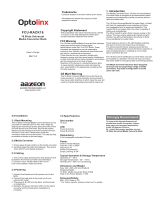
2.1.2 Installing the Media Converter Slide-in-Modules
CAUTION: Wear a grounding device and observe electrostatic discharge precau-
tions when installing the Media Converter Slide-in-Module(s) into the chassis.
Failure to observe this caution could result in damage to, and subsequent failure
of, the Media Converter Slide-in-Module(s).
NOTE: Media Converter Slide-in-Modules can be installed in any installation slot,
in any order.
To install the Media Converter Slide-in-Module into the CPSMC0800-100 8-Slot
chassis:
1. Remove the Media Converter Slide-in-Module protective plate from the instal-
lation slot by removing the one (1) screw that secures the plate to the front of
the chassis.
NOTE: If the Slide-in-Module requires two slots, remove the protective plates
from two (2) adjacent installation slots.
2. Align the Media Converter Slide-in-Module with the chassis installation slot so
that the panel fastener screw is at the left of the Media Converter Slide-in-
Module.
3. Carefully slide the Media Converter Slide-in-Module into the installation slot.
NOTE: Ensure that the Media Converter Slide-in-Module is firmly seated against
the back of the chassis.
4. Install the Media Converter Slide-in-Module by carefully rotating the attached
panel fastener screw clockwise to secure the Media Converter Slide-in-Module
to the chassis.
5. Repeat steps 1 through 4 for additional Media Converter Slide-in-Module(s).
Tech Support: 7am-6pm CST (GMT -6:00) 1-800-260-1312 International: 00-1-952-941-7600
10BASE-T
INPORT
MCCM10
MGMT MASTER
OUTPORT
12C
12C-1TERM
INIT
RX
TX
LNK
PWR
RESET
DB-9
CFETF110
SPD
PWR
FRX
CRX
FLNK
CLNK
10/100TX
RX
TX
10/100SX
LKS
PWR
LKM
Multimode
Singlemode
TX
RX
TX
RX
CFETF110
SPD
PWR
FRX
CRX
FLNK
CLNK
10/100TX
RX
TX
10/100SX
CPSMC-0800
8-Slot Chassis
Mpls, MN 55344
Mpls, MN 55344
Input Power:
Input Power:
110-240 VAC
110-240 VAC
1.6A max. (60W max)
1.6A max. (60W max)
50/60 Hz
50/60 Hz
LKS
PWR
LKM
Multimode
Singlemode
TX
RX
TX
RX
Panel Fastener Screw

8
CPSMC0800-100 PointSystem
™
Chassis
slide-in-modules
Tech Support: 7am-6pm CST (GMT -6:00) 1-800-260-1312 International: 00-1-952-941-7600
2.2.3 Replacing the Media Converter Slide-in-Modules
CAUTION: Wear a grounding device and observe electrostatic discharge precau-
tions when replacing Media Converter Slide-in-Module(s). Failure to observe this
caution could result in damage to, and subsequent failure of, the Media Converter
Slide-in-Module(s).
NOTE: The Media Converter Slide-in-Modules are hot-swappable.
To replace a Media Converter Slide-in-Module:
1. Remove the Media Converter Slide-in-Module to be replaced by loosening the
one (1) screw that secures the Slide-in-Module to the CPSMC0800-100 chassis
front. Slide the Media Converter Slide-In-Module from the CPSMC0800-100
chassis.
2. Align the replacement Media Converter Slide-in-Module with the chassis instal-
lation slot so that the panel fastener screw is to the left.
3. Carefully slide the replacement Media Converter Slide-in-Module into the
installation slot.
NOTE: Ensure that the Media Converter Slide-in-Module is firmly seated against
the back of the chassis.
4. Install the replacement Media Converter Slide-in-Module by carefully rotating
the attached panel fastener screw clockwise to secure the Media Converter
Slide-in-Module to the chassis.
10BASE-T
INPORT
MCCM10
MGMT MASTER
OUTPORT
12C
12C-1TERM
INIT
RX
TX
LNK
PWR
RESET
DB-9
CFETF110
SPD
PWR
FRX
CRX
FLNK
CLNK
10/100TX
RX
TX
10/100SX
LKS
PWR
LKM
Multimode
Singlemode
TX
RX
TX
RX
CFETF110
SPD
PWR
FRX
CRX
FLNK
CLNK
10/100TX
RX
TX
10/100SX
CPSMC-0800
8-Slot Chassis
Mpls, MN 55344
Mpls, MN 55344
Input Power:
Input Power:
110-240 VAC
110-240 VAC
1.6A max. (60W max)
1.6A max. (60W max)
50/60 Hz
50/60 Hz
LKS
PWR
LKM
Multimode
Singlemode
TX
RX
TX
RX
Panel Fastener Screw

9
CPSMC0800-100 PointSystem
™
Chassis
slide-in-modules
Tech Support: 7am-6pm CST (GMT -6:00) 1-800-260-1312 International: 00-1-952-941-7600
2.2 Management Modules
Optional network management is provided by SNMP software embedded in
Transition Networks
PointSystem
™
Management Module(s) that can be installed in
the CPSMC0800-100 8-Slot chassis.
Transition Networks provides two such modules:
• CPSMM-120 Single-Slot Master Management Module.
• CPSMM-200 Dual-Slot Master Management Module.
Along with an additional expansion module:
• CPSMM-210 Single Slot Expansion Management Module
2.2.1 Three Types of Managment Modules
CPSMM-120 Single-Slot Master Managment Module
The optional CPSMM-120 Single-Slot Master Managment Module can
be installed to enable network managment of a single CPSMC0800-100
8-Slot chassis .
Refer to the CPSMM-120 User Guide for more information on the
CPSMM-120 Single-Slot Master Management Module.
CPSMM-200 Dual-Slot Master Management Module
The optional CPSMM-200 Dual-Slot Master Managment Module
can also be installed in the CPSMC0800-100 8-Slot chassis to
enable network managment.
This module has all of the features of the CPSMM-120 plus a pair
of cascade ports, which allow multiple PointSystem chassis to
be connected. See section 4.3 Cascade Option for details on
connecting multiple chassis.
Note also that this module requires two adjacent slots in the
CPSMC0800-100 8-Slot chassis for installation.
Refer to the CPSMM-200/-210 User Guide for more information on the CPSMM-200
Dual-Slot Master Management Module.
CPSMM-210 Single-Slot Expansion Management Module
The CPSMM-210 is used with the CPSMM-200 to connect up to eight (8)
PointSystem™chassis into one managable stack. See section 4.3 Cascade
Option for details.
Refer to the CPSMM-200/-210 User Guide for more information on the
CPSMM-210 Single-Slot Expansion Management Module.
10BASE-T
RX
TX
LNK
PWR
RESET
SERIAL
CPSMM120
10BASE-T
INPORT
CPSMM200
OUTPORT
12C
12C-1TERM
INIT
RX
TX
LNK
PWR
RESET
DB-9
Pwr
RESET
12C
12C-1
TERM
INIT
CPSMM210

10
CPSMC0800-100 PointSystem
™
Chassis
slide-in-modules
Tech Support: 7am-6pm CST (GMT -6:00) 1-800-260-1312 International: 00-1-952-941-7600
2.2.2 Installing the Managment Modules
CAUTION: Wear a grounding device and observe electrostatic discharge precau-
tions when installing the Management Module(s) in the 8-Slot chassis. Failure to
observe this caution could result in damage to, and subsequent failure of, the
Management Module.
Install one (1) Master Management Module (CPSMM-120 or CPSMM-200) in the
primary managed CPSMC0800-100 8-Slot chassis.
If several PointSystem™chassis are to be connected in a cascade fashion (see sec-
tion 4.3 Cascade Option):
• Install one (1) Master Management Module (CPSMM-120 or CPSMM-200) into
the primary managed CPSMC0800-100 8-Slot chassis.
• Install one (1) Master Management Module (CPSMM-200) or one (1) Expansion
Management Module (CPSMM-210) in any secondary managed CPSMC0800-
100 8-Slot chassis.
NOTE: Though the Management Module(s) can be installed in any PointSystem™
chassis slot, use of the left-most installation slot(s) for installing the Management
Module(s) is recommended in order to keep the cascading cables separate from the
network cables connected to the installed on Media Converter Slide-In-Modules.
To install a Management Module:
1a. CPSMM-200 Dual-Slot Master Management Module:
Remove two (2) Management Module protective plates from two (2) installation
slots at the far-left position by removing the one (1) screw that secures each pro-
tective plate to the PointSystem™ chassis.
1b. CPSMM-120 Single-Slot Master Management Module OR
CPSMM-210 Single-Slot Expansion Management Module:
Remove one (1) Management Module protective plate from one (1) installation
slot at the far-left position by removing the one (1) screw that secures the pro-
tective plate to the PointSystem™ chassis.
2. Align the Management Module with the PointSystem™ chassis installation slot
so that the panel fastener screw is to the left of the Management Module.
3. Carefully slide the Management Module into the installation slot, aligning the
Management Module with the installation guides.
NOTE: Ensure that Management Module is firmly seated against backplane.
4. Rotate the attached panel fastener screw clockwise to secure the Management
Module to the PointSystem™ chassis.
PWR
CPSMC-0800
8-Slot Chassis
Mpls, MN 55344
Mpls, MN 55344
Input Power:
Input Power:
110-240 VAC
110-240 VAC
1.6A max. (60W max)
1.6A max. (60W max)
50/60 Hz
50/60 Hz
10BASE-T
INPORT
MCCM10
MGMT MASTER
OUTPORT
12C
12C-1TERM
INIT
RX
TX
LNK
PWR
RESET
DB-9
Panel Fastener Screw

11
CPSMC0800-100 PointSystem
™
Chassis
slide-in-modules
2.2.3 Replacing the Mangement Modules
CAUTION: Wear a grounding device and observe electrostatic discharge precau-
tions when replacing Media Converter Slide-in-Module(s). Failure to observe this
caution could result in damage to, and subsequent failure of, the Management
Module(s).
NOTE: The Managment Modules are NO
T
hot-swappable.
To replace a Managment Module:
1. Remove the Managment Module to be replaced by loosening the one (1) screw
that secures the Managment Module to the CPSMC0800-100 chassis front.
Slide the Management Module from the CPSMC0800-100 chassis.
2. Align the replacement Mangement Module with the installation slot so that the
panel fastener screw is at the top.
3. Carefully slide the replacement Managment Module into the installation slot.
NOTE: Ensure that the Managment Module is firmly seated against the back of
the chassis.
4. Install the replacement Managment Module by carefully rotating the attached
panel fastener screw clockwise to secure the Managment Module to the
chassis.
Tech Support: 7am-6pm CST (GMT -6:00) 1-800-260-1312 International: 00-1-952-941-7600
PWR
CPSMC-0800
8-Slot Chassis
Mpls, MN 55344
Mpls, MN 55344
Input Power:
Input Power:
110-240 VAC
110-240 VAC
1.6A max. (60W max)
1.6A max. (60W max)
50/60 Hz
50/60 Hz
10BASE-T
INPORT
MCCM10
MGMT MASTER
OUTPORT
12C
12C-1TERM
INIT
RX
TX
LNK
PWR
RESET
DB-9
Panel Fastener Screw

12
CPSMC0800-100 PointSystem
™
Chassis
power supply
3 Powering the CPSMC0800-100
The CPSMC0800-100 chassis can be powered through an AC or DC Power Supply.
An optional auxilliary power supply, with Instant Fail Over protections, is also avail-
able.
NOTE: The CPSMC0800-100 8-Slot chassis does not have an ON/OFF switch.
• Power up the chassis by connecting the power supply.
• Power-down the chassis by disconnecting power supply.
WARNING: THE AC AND DC POWER SUPPLIES CONTAIN NO USER-SERVICA-
BLE PARTS. DO NOT ATTEMPT TO SERVICE EITHER POWER SUPPLY. FAILURE
TO OBSERVE THIS CAUTION COULD RESULT IN EQUIPMENT DAMAGE
AND/OR PERSONAL INJURY OR DEATH.
NOTE: Contact Technical Support for any questions concerning power supply.
3.1 Primary Power Supply
The CPSMC0800-100 includes an internal power supply, which is accessed through
a power inlet on the front panel. The power cord is included.
To power the CPSMM0800-100 8-Slot chassis through the Primary Power Supply:
1. Connect the female end of the power cord to the Power Inlet on the front panel
of the chassis.
2. Plug the male end of the power cord into the correct voltage rack or wall sock-
et.
3. Verify that the 8-Slot chassis is powered by observing the illuminated Power
LEDs on the Slide-in-Modules and by the fan operation.
Tech Support: 7am-6pm CST (GMT -6:00) 1-800-260-1312 International: 00-1-952-941-7600
10BASE-T
INPORT
MCCM10
MGMT MASTER
OUTPORT
12C
12C-1TERM
INIT
RX
TX
LNK
PWR
RESET
DB-9
CFETF110
SPD
PWR
FRX
CRX
FLNK
CLNK
10/100TX
RX
TX
10/100SX
LKS
PWR
LKM
Multimode
Singlemode
TX
RX
TX
RX
CFETF110
SPD
PWR
FRX
CRX
FLNK
CLNK
10/100TX
RX
TX
10/100SX
LKS
PWR
LKM
Multimode
Singlemode
TX
RX
TX
RX
CPSMC-0800
8-Slot Chassis
Mpls, MN 55344
Mpls, MN 55344
Input Power:
Input Power:
110-240 VAC
110-240 VAC
1.6A max. (60W max)
1.6A max. (60W max)
50/60 Hz
50/60 Hz
Power Inlet
Power Cord

13
CPSMC0800-100 PointSystem
™
Chassis
power supply
3.2 Auxilliary Power Supply
The CPSMC0800-100 can also be supplied with auxilliary power through the
Auxilliary Power Inlet, located on the back panel. The External Power Converter and
additional power cord are sold separately.
To power the CPSMM0800-100 8-Slot chassis through the Auxilliary Power Supply:
1. Connect the female end of the External Power Converter to the Auxilliary Power
Inlet on the back of the 8-Slot chassis.
2. Connect the female end of the power cord to the male end of the External Power
Converter.
3. Plug the male end of the power cord into the correct voltage AC rack or wall
socket.
4. Verify that the chassis is powered by observing the illuminated Power LEDs on
the Slide-in-Modules and by the fan operation.
Tech Support: 7am-6pm CST (GMT -6:00) 1-800-260-1312 International: 00-1-952-941-7600
Mpls, MN 55344
Input Power:
110-240 VAC
1.6A max. (60W max)
50/60 Hz
Auxilliary Power Inlet
External Power
Converter
Power Cord

14
CPSMC0800-100 PointSystem
™
Chassis
chassis
4 CPSMC0800-100 Chassis
4.1 Installing the CPSMC0800-100 Chassis
The CPSMC0800-100 can be installed in a standard 19-inch rack or on a table,
shelf, or other stable surface.
4.1.1 Standard 19-inch Rack Installation
NOTE: The maximum recommended ambient temperature (Tmra) for the 8-Slot
chassis is 40°C. If the 8-Slot chassis is installed in a closed or mult-unit rack assem-
bly, the operating ambient temperature of the the rack environment may be greater
than room ambient. Consideration should be given to installing the 8-Slot chassis
in an environment compatible with the Tmra.
CAUTION: Installation of the chassis in a rack should be such that the amount of
air flow required for safe operation of the equipment is not compromised .
The 8-Slot chassis is designed so that the installation brackets can be installed to
align the chassis either
flush
against the front or back edge of the rack or
recessed
from the front or back edge of the rack.
WARNING: SELECT MOUNTING BRACKET LOCATIONS ON THE CHASSIS THAT
WILL KEEP THE CHASSIS BALANCED WHEN MOUNTED IN THE RACK. FAILURE
TO OBSERVE THIS WARNING COULD ALLOW THE CHASSIS TO FALL, RESULT-
ING IN EQUIPMENT DAMAGE AND/OR POSSIBLE INJURY TO PERSONNEL.
CAUTION: Consideration should be given to the connection of the chassis to the
supply circuit and the effect that overloading of the circuits might have on over-
current protection and supply wiring. Appropriate consideration of equipment
nameplates should be used when addressing this concern.
CAUTION: Reliable earthing of rack-mounted equipment should be maintained.
Particular attention should be given to supply connections other than direct con-
nections to the branch circuit (e.g., use of power strips).
Tech Support: 7am-6pm CST (GMT -6:00) 1-800-260-1312 International: 00-1-952-941-7600
Recessed Alignment
at back
Flush Alignment
at front
Recessed Alignment
at front
Flush Alignment
at back

15
CPSMC0800-100 PointSystem
™
Chassis
chassis
To install the CPSMC0800-100 8-Slot chassis into a standard 19-inch rack:
1. Determine the preferred alignment of the 8-Slot chassis in the rack.
NOTE: Installation bracket mounting screws are provided. Rackmount screws
and clip nuts are NOT provided.
2. Locate six (6) installation bracket mounting screws (provided) for each chassis
to be installed.
WARNING: Mount the chassis evenly and securely onto the rack. Failure to
observe this warning could allow the chassis to fall, resulting in equipment
damage and/or possible injury to personnel.
3. Align the universal mounting bracket in the selected position against the side of
the chassis so that the chassis installation holes are visible through the univer-
sal bracket installation holes.
4. Using a Phillips screwdriver, install the three (3) screws through the mounting
bracket into the installation holes on side of the chassis.
5. Repeat steps 3 and 4 for the second mounting bracket.
6. Locate four (4) screws (not provided) and optional clip-nuts (not provided) for
each chassis to be installed.
7. Carefully align the chassis at a secure and level position between the 19-inch
site rack mounting rails.
8. Install two (2) screws through the right bracket into the right mounting rail and
two (2) screws through the left bracket into the left mounting rail, using the clip
nuts to secure, if necessary.
4.1.2 Table-Top Installation
The CPSMC0800-100 8-slot chassis is shipped with four (4) rubber feet for optional
installation on a table or other flat, stable surface in a well-ventilated area. If table-
top installation is desired, remove the rubber feet from the card and place one at
each of the four corners on the bottom of the chassis.
Tech Support: 7am-6pm CST (GMT -6:00) 1-800-260-1312 International: 00-1-952-941-7600
Step 4:
10BASE-T
INPORT
MCCM10
MGMT MASTER
OUTPORT
12C
12C-1TERM
INIT
RX
TX
LNK
PWR
RESET
DB-9
CFETF110
SPD
PWR
FRX
CRX
FLNK
CLNK
10/100TX
RX
TX
10/100SX
LKS
PWR
LKM
Multimode
Singlemode
TX
RX
TX
RX
CFETF110
SPD
PWR
FRX
CRX
FLNK
CLNK
10/100TX
RX
TX
10/100SX
LKS
PWR
LKM
Multimode
Singlemode
TX
RX
TX
RX
CPSMC-0800
8-Slot Chassis
Mpls, MN 55344
Mpls, MN 55344
Input Power:
Input Power:
110-240 VAC
110-240 VAC
1.6A max. (60W max)
1.6A max. (60W max)
50/60 Hz
50/60 Hz
10BASE-T
INPORT
MCCM10
MGMT MASTER
OUTPORT
12C
12C-1TERM
INIT
RX
TX
LNK
PWR
RESET
DB-9
CFETF110
SPD
PWR
FRX
CRX
FLNK
CLNK
10/100TX
RX
TX
10/100SX
LKS
PWR
LKM
Multimode
Singlemode
TX
RX
TX
RX
CFETF110
SPD
PWR
FRX
CRX
FLNK
CLNK
10/100TX
RX
TX
10/100SX
LKS
PWR
LKM
Multimode
Singlemode
TX
RX
TX
RX
CPSMC-0800
8-Slot Chassis
Mpls, MN 55344
Input Power:
110-240 VAC
1.6A max. (60W max)
50/60 Hz
Step 8:
Mpls, MN 55344
Input Power:
110-240 VAC
1.6A max. (60W max)
50/60 Hz
10BASE-T
INPORT
MCCM10
MGMT MASTER
OUTPORT
12C
12C-1TERM
INIT
RX
TX
LNK
PWR
RESET
DB-9
CFETF110
SPD
PWR
FRX
CRX
FLNK
CLNK
10/100TX
RX
TX
10/100SX
LKS
PWR
LKM
Multimode
Singlemode
TX
RX
TX
RX
CFETF110
SPD
PWR
FRX
CRX
FLNK
CLNK
10/100TX
RX
TX
10/100SX
LKS
PWR
LKM
Multimode
Singlemode
TX
RX
TX
RX
CPSMC-0800
8-Slot Chassis
Mpls, MN 55344
Input Power:
110-240 VAC
1.6A max. (60W max)
50/60 Hz

16
CPSMC0800-100 PointSystem
™
Chassis
chassis
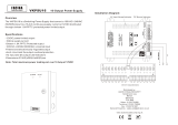
4.2 Cascade Option
The Management Module cascade option allows the network administrator to con-
nect up to eight (8) CPSMC0800-100 8-Slot chassis into one manageable stack, pro-
viding a single management source for up to 55 installed Media Converter devices.
To create the cascade option, the CPSMM-200 Dual Slot Master Management
Module is installed in the first chassis in the series. The CPSMM-210 Single-Slot
Expansion Management Module is installed in each subsequent chassis.
An alternative setup involves installing two CPSMC-200 Dual-Slot Master
Management Modules into two adjacent chassis chassis for redundant management.
Tech Support: 7am-6pm CST (GMT -6:00) 1-800-260-1312 International: 00-1-952-941-7600
The CPSMM-200
Management Module is
installed in the first
chassis in the series
10BASE-T
INPORT
MCCM10
MGMT MASTER
OUTPORT
12C
12C-1TERM
INIT
RX
TX
LNK
PWR
RESET
DB-9
CFETF110
SPD
PWR
FRX
CRX
FLNK
CLNK
10/100TX
RX
TX
10/100SX
LKS
PWR
LKM
Multimode
Singlemode
TX
RX
TX
RX
CFETF110
SPD
PWR
FRX
CRX
FLNK
CLNK
10/100TX
RX
TX
10/100SX
LKS
PWR
LKM
Multimode
Singlemode
TX
RX
TX
RX
CPSMC-0800
8-Slot Chassis
Mpls, MN 55344
Mpls, MN 55344
Input Power:
Input Power:
110-240 VAC
110-240 VAC
1.6A max. (60W max)
1.6A max. (60W max)
50/60 Hz
50/60 Hz
CFETF110
SPD
PWR
FRX
CRX
FLNK
CLNK
10/100TX
RX
TX
10/100SX
LKS
PWR
LKM
Multimode
Singlemode
TX
RX
TX
RX
CFETF110
SPD
PWR
FRX
CRX
FLNK
CLNK
10/100TX
RX
TX
10/100SX
LKS
PWR
LKM
Multimode
Singlemode
TX
RX
TX
RX
CPSMC-0800
8-Slot Chassis
Mpls, MN 55344
Mpls, MN 55344
Input Power:
Input Power:
110-240 VAC
110-240 VAC
1.6A max. (60W max)
1.6A max. (60W max)
50/60 Hz
50/60 Hz
Pwr
RESET
12C
12C-1
TERM
INIT
The CPSMM-210
Management Module is
installed in each
subsequent chassis
CFETF110
SPD
PWR
FRX
CRX
FLNK
CLNK
10/100TX
RX
TX
10/100SX
LKS
PWR
LKM
Multimode
Singlemode
TX
RX
TX
RX
CFETF110
SPD
PWR
FRX
CRX
FLNK
CLNK
10/100TX
RX
TX
10/100SX
LKS
PWR
LKM
Multimode
Singlemode
TX
RX
TX
RX
CPSMC-0800
8-Slot Chassis
Mpls, MN 55344
Mpls, MN 55344
Input Power:
Input Power:
110-240 VAC
110-240 VAC
1.6A max. (60W max)
1.6A max. (60W max)
50/60 Hz
50/60 Hz
Pwr
RESET
12C
12C-1
TERM
INIT
CFETF110
SPD
PWR
FRX
CRX
FLNK
CLNK
10/100TX
RX
TX
10/100SX
LKS
PWR
LKM
Multimode
Singlemode
TX
RX
TX
RX
CFETF110
SPD
PWR
FRX
CRX
FLNK
CLNK
10/100TX
RX
TX
10/100SX
LKS
PWR
LKM
Multimode
Singlemode
TX
RX
TX
RX
CPSMC-0800
8-Slot Chassis
Mpls, MN 55344
Mpls, MN 55344
Input Power:
Input Power:
110-240 VAC
110-240 VAC
1.6A max. (60W max)
1.6A max. (60W max)
50/60 Hz
50/60 Hz
Pwr
RESET
12C
12C-1
TERM
INIT
The CPSMM-200
Management Module is
installed in the first
chassis in the series
Another CPSMM-200
Managment Module is
installed in the next
chassis as a backu
p
10BASE-T
INPORT
MCCM10
MGMT MASTER
OUTPORT
12C
12C-1TERM
INIT
RX
TX
LNK
PWR
RESET
DB-9
CFETF110
SPD
PWR
FRX
CRX
FLNK
CLNK
10/100TX
RX
TX
10/100SX
LKS
PWR
LKM
Multimode
Singlemode
TX
RX
TX
RX
CFETF110
SPD
PWR
FRX
CRX
FLNK
CLNK
10/100TX
RX
TX
10/100SX
LKS
PWR
LKM
Multimode
Singlemode
TX
RX
TX
RX
CPSMC-0800
8-Slot Chassis
Mpls, MN 55344
Mpls, MN 55344
Input Power:
Input Power:
110-240 VAC
110-240 VAC
1.6A max. (60W max)
1.6A max. (60W max)
50/60 Hz
50/60 Hz

17
CPSMC0800-100 PointSystem
™
Chassis
chassis
To cascade two or more CPSMC0800-100 8-Slot chassis:
1. Locate one (1) Transition Networks CPSMC0800-100 Management Module cas-
cade cable (with RJ-45 connectors installed at both ends) for each set of two (2)
chassis to be cascaded.
NOTE: Transition Networks Management Module cascade cables are one (1)
meter long. Ensure that the chassis are installed within one (1) meter of each
other.
2. At the first chassis in the series: Plug the RJ-45 connector at one end of the cas-
cade cable into the Management Module’s RJ-45 port labeled “OUTPUT”.
3. At the next chassis in the series: Plug the RJ-45 connector at the other end of
the cascade cable into the Management Module’s RJ-45 port labeled “INPUT”.
4. At the same chassis as in step 3: Plug the RJ-45 connector at one end of the
cascade cable into the Management Module’s RJ-45 port labeled “OUTPUT”.
5. At the next chassis in the series: Plug the RJ-45 connector at the other end of
the cascade cable into the Management Module’s RJ-45 port labeled “INPUT”.
6. Repeat steps 4 and 5 until all chassis have been connected.
4.3 Connecting the Slide-in-Modules to the Network
Once the CPSMC0800-100 chassis has been installed, the Media Converter Slide-
in-Modules may be connected to the network.
CAUTION: Connect input/output network cables ONLY to Media Converter Slide-
In-Module connectors within the same network protocol (such as Ethernet-to-
Ethernet, Fast Ethernet-to-Fast Ethernet, ATM-to-ATM). Failure to observe this cau-
tion will cause data transfer to fail.
Refer to User’s Guides included with the Media Converter Slide-In-Modules for
cabling specifications and instructions.
Tech Support: 7am-6pm CST (GMT -6:00) 1-800-260-1312 International: 00-1-952-941-7600
10BASE-T
INPORT
MCCM10
MGMT MASTER
OUTPORT
12C
12C-1TERM
INIT
RX
TX
LNK
PWR
RESET
DB-9
CFETF110
SPD
PWR
FRX
CRX
FLNK
CLNK
10/100TX
RX
TX
10/100SX
LKS
PWR
LKM
Multimode
Singlemode
TX
RX
TX
RX
CFETF110
SPD
PWR
FRX
CRX
FLNK
CLNK
10/100TX
RX
TX
10/100SX
LKS
PWR
LKM
Multimode
Singlemode
TX
RX
TX
RX
CPSMC-0800
8-Slot Chassis
Mpls, MN 55344
Mpls, MN 55344
Input Power:
Input Power:
110-240 VAC
110-240 VAC
1.6A max. (60W max)
1.6A max. (60W max)
50/60 Hz
50/60 Hz
Check the individual User's Guides for specific information on
how to connect each Slide-in-Module to the network.

18
CPSMC0800-100 PointSystem
™
Chassis
chassis
Tech Support: 7am-6pm CST (GMT -6:00) 1-800-260-1312 International: 00-1-952-941-7600
4.4 Operation
Daily operation of the CPSMC0800-100 8-Slot chassis requires no network admin-
istrator activity except for the occasional monitoring of the status LED indicators on
the installed Media Converter Slide-In-Modules.
Each Media Converter Slide-in-Module and each Management Slide-in-Module has
one or more LED indicators to help monitor the CPSMC0800-100 PointSystem™
chassis network.
Refer to the User’s Guide included with each Transition Networks Slide-in-Module
to interpret the LED indicators on the Managment and Media Converter modules.
10BASE-T
INPORT
MCCM10
MGMT MASTER
OUTPORT
12C
12C-1TERM
INIT
RX
TX
LNK
PWR
RESET
DB-9
CFETF110
SPD
PWR
FRX
CRX
FLNK
CLNK
10/100TX
RX
TX
10/100SX
LKS
PWR
LKM
Multimode
Singlemode
TX
RX
TX
RX
CFETF110
SPD
PWR
FRX
CRX
FLNK
CLNK
10/100TX
RX
TX
10/100SX
LKS
PWR
LKM
Multimode
Singlemode
TX
RX
TX
RX
CPSMC-0800
8-Slot Chassis
Mpls, MN 55344
Mpls, MN 55344
Input Power:
Input Power:
110-240 VAC
110-240 VAC
1.6A max. (60W max)
1.6A max. (60W max)
50/60 Hz
50/60 Hz
LED Indicators on the Management Module and Slide-in-Modules

19
CPSMC0800-100 PointSystem
™
Chassis
SNMP
Tech Support: M-F 7am-6pm CST (GMT -6:00) 1-800-260-1312 International: 00-1-952-941-7600
5 SNMP Agent in the Management Module
Both Management Modules (CPSMM-120 and (CPSMM-200) have an SNMP
(Simple Network Managment Protocol) Agent installed in the module that allows
remote managment of networked devices.
The SNMP agent includes the Transition Networks PointSystem™ Command Line
Interface (CLI) and an embedded Telnet server.
These tools allow the network adminsitrator to configure and manage the
CPSMC0800-100 8-Slot from an attached terminal or from a remote, networked
computer.
In addition, Transition Networks FocalPoint™ software can be installed in the net-
worked computer to provide a graphical user interface to monitor the Conversion
Center.
5.1 SNMP Hardware Connections
The SNMP software can be accessed either through the Management Module’s DB-
9 serial port or through the RJ-45 Ethernet™ port.
DB-9 Serial Port
The DB-9 serial port allows the network administrator to configure and manage the
CPSMC0800-100 8-Slot chassis using the SNMP Command-Line Interface (CLI) at
an attached terminal or terminal emulator.
Use a null modem cable to attach a terminal to the DB-9 serial port on the
Management Module as shown.
10BASE-T
INPORT
CPSMM200
OUTPORT
12C
12C-1TERM
INIT
RX
TX
LNK
PWR
RESET
DB-9
10BASE-T
RX
TX
LNK
PWR
RESET
SERIAL
CPSMM120
RJ-45 Ethernet Port
CPSMM-200 CPSMM-120
DB-9 Serial Port
10BASE-T
INPORT
MCCM10
MGMT MASTER
OUTPORT
12C
12C-1TERM
INIT
RX
TX
LNK
PWR
RESET
DB-9
CFETF110
SPD
PWR
FRX
CRX
FLNK
CLNK
10/100TX
RX
TX
10/100SX
LKS
PWR
LKM
Multimode
Singlemode
TX
RX
TX
RX
CFETF110
SPD
PWR
FRX
CRX
FLNK
CLNK
10/100TX
RX
TX
10/100SX
LKS
PWR
LKM
Multimode
Singlemode
TX
RX
TX
RX
CPSMC-0800
8-Slot Chassis
Mpls, MN 55344
Mpls, MN 55344
Input Power:
Input Power:
110-240 VAC
110-240 VAC
1.6A max. (60W max)
1.6A max. (60W max)
50/60 Hz
50/60 Hz
Attached terminal or terminal emulator
connected to the DB-9 serial port
via null modem cable.

20
CPSMC0800-100 PointSystem
™
Chassis
SNMP
Tech Support: M-F 7am-6pm CST (GMT -6:00) 1-800-260-1312 International: 00-1-952-941-7600
RJ-45 Ethernet™ Port
The RJ-45 Ethernet™ Port allows the network administrator to manage the
CPSMC1800-100 8-Slot chassis via a remote Network Management Station (NMS)
in one of two ways:
1. Using the Transition Networks FocalPoint™ graphical user interface.
2. Using a remote Telnet connection.
Use an RJ-45 network cable to attach a terminal (via a network hub or switch) to the
RJ-45 Ethernet™port on the Management Module as shown.
NOTE: To manage the PointSystem™ chassis via a remote NMS, both the RJ-45
Ethernet™ port and the NMS must be connected to a network with Internet accesi-
bility.
5.2 SNMP Software
The SNMP software is described in a separate manual available from Transition
Networks.
10BASE-T
INPORT
MCCM10
MGMT MASTER
OUTPORT
12C
12C-1TERM
INIT
RX
TX
LNK
PWR
RESET
DB-9
CFETF110
SPD
PWR
FRX
CRX
FLNK
CLNK
10/100TX
RX
TX
10/100SX
LKS
PWR
LKM
Multimode
Singlemode
TX
RX
TX
RX
CFETF110
SPD
PWR
FRX
CRX
FLNK
CLNK
10/100TX
RX
TX
10/100SX
LKS
PWR
LKM
Multimode
Singlemode
TX
RX
TX
RX
CPSMC-0800
8-Slot Chassis
Mpls, MN 55344
Mpls, MN 55344
Input Power:
Input Power:
110-240 VAC
110-240 VAC
1.6A max. (60W max)
1.6A max. (60W max)
50/60 Hz
50/60 Hz
Network hub or switch connected
to the RJ-45 Ethernet port.
Remote Telnet connection O
R
Remote NMS with an SNMP application
/