Setting Up Your Dell EMC SCv3000 and SCv3020 Storage System (iSCSI Front End)
To add capacity to your storage system, you can connect SCv300, SCv320, or SCv360 expansion enclosures to an SCv3000 series storage system.
Each expansion enclosure includes two Enclosure Management Modules (EMM) in two interface slots.
NOTE: If the storage system is installed without expansion enclosures, do not interconnect the back-end SAS ports on the storage controllers.
1. Power on any network switches, routers, or other standalone
components.
2. Power on any expansion enclosures that might be a part of the system.
3. Power on the storage system by turning on both power supply/cooling
fan modules.
CAUTION: Do not power off the storage system until it can be
discovered with the Dell Storage Manager Client. During the initial
power up, the storage system might take up to twenty minutes to boot
completely.
The Unisphere web interface provides access to the initial setup wizards. The wizards help you remotely discover and configure storage
systems.
To access the Initialize Storage Center wizard from the Data Collector
1. Open a web browser.
2. Type the address of the Data Collector in the browser using the following format:
https://Data Collector host name or IP address:3033/
3. Type the user name and password of a Data Collector user in the User Name and Password fields.
4. Click Log In.
The web broser connects to the Data Collector and displays the Unisphere Central Home page.
5. From the Unisphere Central Home page, click (New), and select Initalize Storage Center.
The Initialize Storage Center wizard opens and the Introduction page is displayed.
6. Follow the prompts in the Initialize Storage Center wizard to proceed.
To access the Initialize Storage Center wizard by connecting directly to a Storage Center
NOTE: The Storage Center must be installed on a DHCP-enabled network.
1. Open a web browser.
2. Type the service tag or IP address of the Storage Center in the browser using the following format:
https://Storage Center service tag or IP address/
3. Type Admin in the User Name field.
4. Type mmm in the Password field.
5. Click Log In.
The web browser connects to the Storage Center and the Change Password dialog box is displayed in the Unisphere interface.
6. Type mmm in the Current Password field.
7. Type a new password for the Admin user in the New Password and Confirm New Password fields.
8. Click OK.
The Initialize Storage Center wizard opens and the Welcome page is displayed.
9. Follow the prompts in the Initialize Storage Center wizard to proceed.
If you do not have access to a Data Collector and you are unable to connect directly to a Storage Center, use the Unisphere Discovery
Utility to discover and initialize a Storage Center.
8
6
9
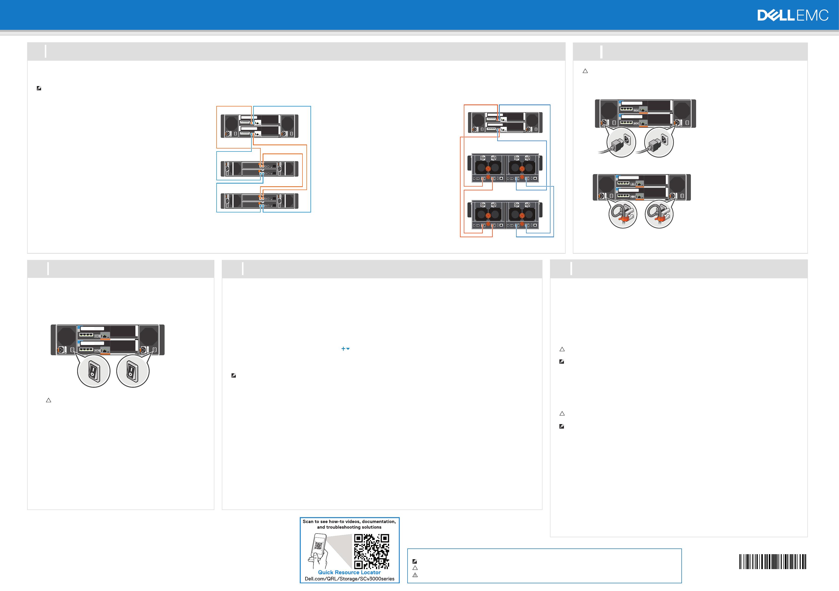
Power on Storage System Components
Cable the Backend
Discover and Configure the Storage Center
Cable SCv300 or SCv320 Expansion
Enclosures
To connect SCv300 or SCv320 expansion enclosures to the storage
system:
Chain 1: A Side (Orange)
1. Connect port 1 on the top storage controller to port 1 on the top
EMM of the first expansion enclosure.
2. Connect the remaining expansion enclosures in series from port
2 to port 1 using the top EMMs.
3. Connect port 2 on the top EMM of the last expansion enclosure
to port 2 on the bottom storage controller.
Chain 1: B Side (Blue)
1. Connect port 1 on bottom storage controller to port 1 on the
bottom EMM of the first expansion enclosure.
2. Connect the remaining expansion enclosures in series from port
2 to port 1 using the bottom EMM.
3. Connect port 2 on the bottom EMM of the last expansion
enclosure to port 2 on the top storage controller.
Information in this document is subject to change without notice.
Reproduction of this material in any manner whatsoever without the written permission of Dell is strictly forbidden.
Copyright © 2019 Dell Inc. or its subsidiaries. All rights reserved. Dell, EMC, and other trademarks are trademarks of Dell Inc. or its
subsidiaries. Other trademarks may be trademarks of their respective owners.
Notes, Cautions, and Warnings
A NOTE indicates important information that helps you make better use of your product.
A CAUTION indicates potential damage to hardware or loss of data and tells you how to avoid the problem.
A WARNING indicates a potential for property damage, personal injury, or death.
Cable SCv360 Expansion Enclosures
To connect SCv360 expansion enclosures to the storage
system:
Chain 1: A Side (Orange)
1. Connect port 1 on the top storage controller to port 1
on the left EMM of the first expansion enclosure.
2. Connect the remaining expansion enclosures in series
from port 3 to port 1 using the left EMMs.
3. Connect port 3 on the left EMM of the last expansion
enclosure to port 2 on the bottom storage controller.
Chain 1: B Side (Blue)
1. Connect port 1 on bottom storage controller to port 1
on the right EMM of the first expansion enclosure.
2. Connect the remaining expansion enclosures in series
from port 3 to port 1 using the right EMM.
3. Connect port 3 on the right EMM of the last
expansion enclosure to port 2 on the top storage
controller.
CAUTION: Make sure that the power switches are in the OFF position
before connecting the power cables.
1. Connect the power cables to both power supply/cooling fan modules in the storage system
chassis.
2. Use the velcro straps to secure the power cables to the storage system chassis.
3. Plug the other end of the power cables into a grounded electrical outlet or a separate power
source such as an uninterrupted power supply (UPS) or a power distribution unit (PDU).
7
Connect the Power Cables
10
Attach the Host Servers
Refer to the Dell EMC Storage Compatibility Matrix for a list of supported iSCSI network adapters.
Windows and Linux Hosts
Install the iSCSI HBAs or network adapters, install the drivers, and make sure that the latest supported BIOS
is installed.
1. Install the iSCSI HBAs or network adapters dedicated for iSCSI traffic in the host servers.
2. Install supported iSCSI HBA drivers and make sure that iSCSI HBAs have the latest supported firmware.
3. Use the iSCSI cabling diagrams to cable the host servers to switches. Connecting host servers directly
to the storage system without using Ethernet switches is not supported.
4. Assign IP addresses to each iSCSI port to match the subnets for each fault domain.
CAUTION: Make sure to assign the correct IP addresses to the HBAs or network adapters. Assigning IPs
to the wrong ports can cause connectivity issues.
NOTE: If using jumbo frames, enable and configure jumbo frames on all devices in the data path.
VMware ESXi Hosts
Install the iSCSI HBAs or network adapters (NICs) and make sure that the latest supported BIOS is installed.
1. Install the iSCSI HBAs or NICs dedicated for iSCSI traffic in the ESXi hosts.
2. Use the iSCSI cabling diagrams to cable the ESXi hosts to switches. Connecting ESXi hosts directly to the
storage system without using Ethernet switches is not supported.
3. Create a VMkernel port for each iSCSI HBA or NIC to be used for iSCSI.
4. Assign IP addresses for each adapter port to match the subnets for each fault domain.
CAUTION: Make sure to assign the correct IP addresses to the HBAs or network adapters. Assigning IPs
to the wrong ports can cause connectivity issues.
NOTE: If using jumbo frames, enable and configure jumbo frames on all devices in the data path: adapter
ports, switches, and storage system.
5. If using the software iSCSI initiator and the server has iSCSI offload, the iSCSI hardware initiator must be
disabled.
6. If using iSCSI HBAs, configure Network Port Binding to add the VMkernel ports to the iSCSI
Storage Adapter. Do not bind NICs to the software initiator.
7. If using software iSCSI initiator, add the Storage Center's iSCSI target IPs to the Dynamic Discovery.
Configure Host Access to a Storage Center
1. For Windows and Linux servers, click the Configure this host to access a Storage Center link and log
in to the Storage Center.
For VMware ESXi servers, click Configure VMware vSphere to access a Storage Center.
2. Follow the steps in the wizard to configure the host to access the Storage Center and configure best
practices for performing I/O.
When the host configuration is complete, use the Storage Manager Client to create and map volumes.
0FDX2PA00

