Page is loading ...

MAINTENANCE INSTRUCTIONS
DHP-H, DHP-L, DHP-C, DHP-A, DHP-AL
Navigate through the control computer’s menu by:
To increase or reduce the set values use:
To adjust the room temperature: starting by pressing
The degree information that now appears in the display is the
last desired room temperature.
To increase the temperature: press
To lower the temperature: press
The temperature you now require is registered immediately.
(After approximately ten seconds the desired room tempera-
ture appears in the display again, together with other infor-
mation.) The heat pump now starts to work to reach the new
temperature.
Want to know more? Read the Maintenance instructions!
VUBMA202

Danfoss – 2 VUBMA202

Danfoss – 3
VUBMA202
Table of contents
1 Important information........................................................4
1.1 Safety precautions .......................................................................4
1.2 Protection ...............................................................................5
2 About your heat pump........................................................6
2.1 Principles of function ....................................................................6
2.2 Components.............................................................................7
2.3 Auxiliary heat, DHP-H, DHP-L, DHP-C ..........................................................8
2.4 Auxiliary heat, DHP-A, -AL .....................................................................8
2.5 Water heater, DHP-H, DHP-C ..................................................................9
2.6 Water heater, DHP-A, -AL .....................................................................10
2.7 Regulation information .................................................................10
2.8 Installation principle, DHP-H, DHP-C .........................................................17
2.9 Installation principle, DHP-L .................................................................18
2.10 Installation principle, DHP-A .................................................................19
2.11 Installation principle, DHP-AL ................................................................20
3 Control computer ...........................................................21
3.1 Display .................................................................................22
3.2 Menus..................................................................................25
4 Trimming the heating system ................................................32
5 Instructions ................................................................33
5.1 Setting operating mode.................................................................33
5.2 Setting ROOM values ...................................................................33
5.3 Adjusting CURVE values.................................................................33
5.4 Adjusting a specific part of the heat curve ...............................................34
5.5 Setting MIN and MAX values ............................................................34
5.6 Setting HEATSTOP ......................................................................34
5.7 Reading off temperatures ...............................................................35
5.8 Calculating energy consumption, DHP-H, DHP-L, DHP-C.....................................35
5.9 Calculating energy consumption, DHP-A, -AL................................................36
5.10 Manual defrost, DHP-A, -AL ..................................................................37
6 Regular checks ..............................................................38
6.1 Checking operation.....................................................................38
6.2 Checking the brine level ................................................................38
6.3 Checking the water level in the heating system..........................................39
6.4 Checking the safety valve ...............................................................39
6.5 In the event of leakage..................................................................40
6.6 Cleaning the strainer for the heating system.............................................40
6.7 Cleaning the strainer for the brine circuit ................................................41
7 Accessories .................................................................42
7.1 Room temperature sensor...............................................................42
8 Troubleshooting ............................................................43
8.1 Alarm...................................................................................43
9 Terms and abbreviations.....................................................45
10 Default settings in the control computer ......................................46
11 References ..................................................................47
11.1 Installation carried out by: ..............................................................48

Danfoss – 4 VUBMA202
1 Important information
• If the installation is not used during the winter, the heating system must be drained of
water, otherwise there is a risk of frost damage to the installation. (Contact an authorized
installer, see the ”References” section)
• The installation can be considered maintenance free but certain checks are necessary (see
“Regular checks”).
• Before changing the control computer’s settings, first find out what these changes mean.
• Contact your installer for any service work.
1.1 Safety precautions
Installation and maintenance
• Only authorized installers may install, operate and carry out maintenance and repair work
on the heat pump. (See the ”References” section)
• Only authorized electricians may modify the electrical installation. (See the ”References”
section)
⚠
DANGER TO LIFE! Only authorized refrigeration technicians may work on the refriger-
ant circuit. (See the “Reference list” section.)
System modifications
Only authorized installers may carry out modifications on the following components:
• The heat pump unit
• The pipes for the refrigerant, brine, water and power
• The safety valve
You must not carry out construction installations that may affect the operational safety of the
heat pump.
Safety valve
The following safety precautions apply to the hot water circuit’s safety valve with correspond-
ing overflow pipe:
• Never block the connection to the safety valve’s overflow pipe.
• Water expands when it is heated, this means that a small amount of water is released
from the system via the overflow pipe. The water that exits the overflow pipe can be hot!
Therefore, allow it to flow to a floor drain where there is no risk of burning yourself.

Danfoss – 5
VUBMA202
1.2 Protection
Corrosion Protection
Due to the risk of corrosion, avoid using different types of sprays in the vicinity of the heat
pump. This particularly applies to:
• Solvents
• Chlorinated cleaning agents
• Paints
• Adhesives

Danfoss – 6 VUBMA202
2 About your heat pump
2.1 Principles of function
A heat pump utilises the free energy found in a natural heat source, such as rock, ground, or
ground water. The heat pump can be compared to a reversed refrigerator. In a refrigerator, heat
is transferred from the inside of the refrigerator to the outside. In a heat pump the heat that is
stored in a heat source is transferred to the inside of the house. The heat pump uses the energy in
the heat source and gives back two to three times more heat energy than what it uses in electri-
cal energy. The heat pump is, therefore, a very environmentally friendly and economical way of
heating a house.
In order for the heat pump to be able to retrieve heating energy from the heat source and trans-
fer it to the heating system of the house, three separate fluid circuits are required.
The circuit that retrieves the heating energy from the heat source is called the brine circuit and it
maintains a low outgoing temperature to be heated by the heat source.
The next circuit is called the refrigerant circuit and is a closed circuit which takes the retrieves
heating energy and transfers it to the last circuit, the heat transfer fluid circuit.
The heat transfer fluid circuit holds the fluid that circulates in the heating system of the house
and in the heat pump’s water heater.
The figure below shows how the different circuits work together in the transfer of heating energy.
Figure 1: Function principles of a heat pump.
1 A fluid (brine) filled hose is lowered into a lake, buried in the ground or lowered into bed-
rock. The brine obtains energy from the heat source by the fluid temperature in the hose
being heated a few degrees by the surrounding heat source. The fluid filled hose is also
known as a collector.
2 The brine is guided into the heat pump’s evaporator. The enclosed refrigerant in the
Expansion valve/
pressure drop
Enclosed
refrigerant
Compressor/
pressure increasing
Brine
Condenser
Evaporator
Heat transfer fluid circuit – is the circuit that contains
the water that transports the heat/energy to the heating
system and the water heater.
Refrigerant circuit – is the circuit that contains a chlorine
and freon free refrigerant which, inside the heat pump,
transfers the energy retrieved from the brine circuit
through evaporation, compression and condensation,
and supplies it to the heat transfer fluid circuit.
Brine circuit – is the circuit that contains an antifreeze
water based mix that obtains and transports energy from
the heat source to the heat pump. This circuit is also
known as the collector.
Rock, ground or ground water
Heating system and
water heater

Danfoss – 7
VUBMA202
1
4
3
5
2
Figure 2: Heat pump components.
2.2 Components
The Danfoss heat pump is a complete heat pump installation for heating and hot water. It has
the market’s first compressor developed solely for heat pumps. It has an integrated 180 litre
water heater and auxiliary heating. The water heater uses TWS, which stands for Tap Water
Stratificator, which is technology that results in more effective
heat transfer and effective layering of the water in the water
heater.
The Danfoss heat pump is equipped with control equipment,
which is controlled via a control panel.
Heat enters the house via a water borne heating system, a
low temperature system. The heat pump supplies as much
of the heat demand as possible before auxiliary heating is
engaged and assists.
The Danfoss heat pump unit consists of five basic units:
1 Heat pump unit
• Scroll compressor
• Stainless steel heat exchanger
• Circulation pumps for brine and heating systems
• Valves and safety equipment for cooling systems and
corresponding electrical components.
2 Water heater
• 180 litres
• Internal anti-corrosion protection with copper or stain-
less steel
• It does not have an anode, which makes it maintenance
free
3 Exchange valve
• The heated water either passes through to the heating
system or to the water heater depending on whether
heating or hot water is to be produced
refrigerant circuit is forced to boil as the pressure in the expansion valve drops and
later evaporates to a gas in the evaporator. The energy produced during this process is
released by the heated brine.
3 The refrigerant that now contains a large quantity of energy in the form of heat is trans-
ferred to the compressor, which both increases its temperature and pressure.
4 The refrigerant then continues to the condenser. When condensing, the refrigerant
supplies its heat energy to the heat transfer fluid circuit. The refrigerant’s temperature
decreases and returns to a liquid state.
5 The heat transfer fluid circuit transports the heat energy out to the water heater, radiator
or the under floor heating system, which heat up.
6 The refrigerant is then transported through the expansion valve where the pressure
drops and the refrigerant starts to boil and then the process starts again.

Danfoss – 8 VUBMA202
4 Auxiliary heat
• 9 kW electric heating element (DHP-A, -AL: 15 kW electric heating element)
• Electric heating element control in a maximum of three steps (DHP-A, -AL: maximum of
five steps)
• Installed on the heating system’s supply pipe
• Covers the demand of extra energy if the heat pump’s capacity is exceeded
• Automatically connected in the heat pump unit if operating mode AUTO is selected.
5 Control equipment
• Control computer with graphic display
• Temperature sensors (outdoor, supply pipe, return pipe, brine in, brine out and hot
water)
• Room sensor (option)
The control equipment controls the heat pup unit’s included components (compressor, circu-
lation pumps, auxiliary heaters and exchange valve) and determines when to start and stop
the pump as well as producing heat for the house or hot water.
2.3 Auxiliary heat, DHP-H, DHP-L, DHP-C
If the heat demand is greater than the heat pump’s capacity, the auxiliary heater engages
automatically. The auxiliary heater is made up of an electric heating element on the supply
pipe that has two outputs, ADD.HEAT 1 and ADD.HEAT 2, and can be controlled in three steps:
• Step 1 = ADD.HEAT 1 = 3 kW
• Step 2 = ADD.HEAT 2 = 6 kW
• Step 3 = ADD.HEAT 1 + ADD.HEAT 2 = 9 kW
To calculate the total energy consumption, see the ”Settings- Calculating energy consump-
tion” section.
In the event of an alarm, the auxiliary heater engages automatically.
2.4 Auxiliary heat, DHP-A, -AL
The auxiliary heater is made up of an electric heating element on the supply pipe that has
three outputs, ADD.HEAT 1, ADD.HEAT 2 and ADD.HEAT 3, and can be controlled in five steps:
• Step 1 = ADD.HEAT 1 = 3 kW
• Step 2 = ADD.HEAT 2 = 6 kW
• Step 3 = ADD.HEAT 1 + ADD.HEAT 2 = 9 kW
• Step 4 = ADD.HEAT 2 + ADD.HEAT 3 = 12 kW
• Step 5 = ADD.HEAT 1 + ADD.HEAT 2 + ADD.HEAT 3 = 15 kW
To calculate the total energy consumption, see the ”Settings- Calculating energy consump-
tion” section.
In the event of an alarm, the auxiliary heater engages automatically.

Danfoss – 9
VUBMA202
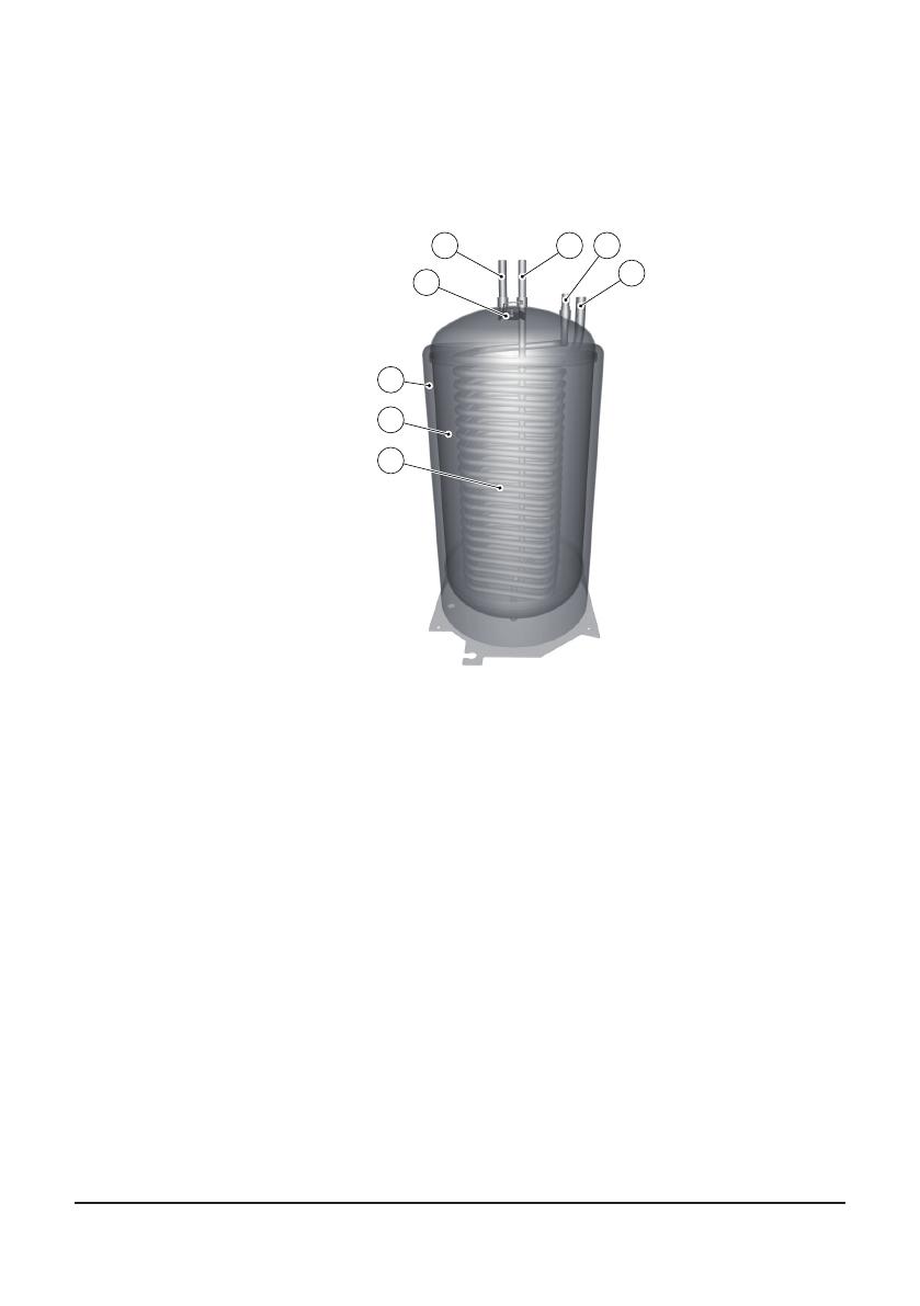
2.5 Water heater, DHP-H, DHP-C
Danfoss heat pumps DHP-H, DHP-C, are supplied with an integrated 180 litre water heater.
Figure 3: Water heater in DHP-H and DHP-C.
Using a regular time interval, the water in the water heater is heated to 60°C to prevent the
build up of bacteria (legionella function). The factory set time interval is seven days.
Hot water production is prioritised ahead of heat production, i.e. no heat is produced if there
is a hot water demand at the same time.
The temperature of the hot water cannot be adjusted. Hot water production does not cease
at a determined temperature but when the compressor’s operating pressure switch reaches
its maximum operating pressure, which corresponds to a hot water temperature of approxi-
mately 50-55°C.
In the control computer’s TEMPERATURE menu, a number of measured and calculated tem-
peratures for the hot water and supply are displayed. There you can see the current hot water
temperature and the temperature of the supply pipe during heating and hot water produc-
tion. The temperature of the supply pipe often exceeds the maximum permitted hot water
temperature, but usually during hot water production.
1 7 8
2
3
4
6
5
Position Name
1 Hot water line
2 Temperature sensors
3 Water heater
4 TWS coil
5 Start temperature sensor
Danfoss – 10 VUBMA202
2.6 Water heater, DHP-A, -AL
Danfoss DHP-A is supplied with an integrated 180 litre water heater. Danfoss DHP-AL is supplied
with an external 180 litre water heater positioned to the side of the heat pump. Both hot water
heaters require a tank outside the water heater that contains defrosting liquid. The difference
between these water heaters and other models is the defrost function of the outdoor unit, oth-
erwise they are the same and have the same functions.
Figure 4: Water heater in DHP-A, -AL.
2.7 Regulation information
Heat production - calculating
The indoor temperature is adjusted by changing the heat pump’s heat curve, which is the con-
trol computer’s tool for calculating what the supply temperature should be for water that is sent
out in the heating system. The supply temperature is calculated from the outdoor temperature
and two adjustable values: CURVE and ROOM. The lower the outdoor temperature, the higher
the supply temperature required. In other words, the supply temperature of the water fed to
the heating system will increase exponentially as the outside air temperature falls.
The heat curve will be adjusted in connection with installation. It must be adapted later on,
however, to obtain a pleasant indoor temperature in any weather conditions. A correctly set
heat curve reduces maintenance and saves energy.
CURVE
The control computer shows the value for CURVE by means of a graph in the display. You can
set the heat curve by adjusting the CURVE value. The CURVE value indicated which supply tem-
perature the heating system is to have at an outdoor temperature of 0°C.
Position Name
1 Hot water line
2 Temperature sensors
3 Tank for anti-freeze
4 Water heater
5 TWS coil
1 6 7
8
2
3
4
5

Danfoss – 11
VUBMA202
Figure 5: Graph showing the set value 40 for CURVE.
At outdoor temperatures colder than 0°C, supply water hotter than 40°C is sent out to the
heating system and at outdoor temperatures greater than 0°C, supply water cooler than 40°C
is sent out.
Figure 6: Increasing or reducing the CURVE changes the slope of the curve
If you increase the CURVE value, the heat curve will become steeper and when you reduce it,
it will become flatter.
The most energy efficient and cost effective setting is achieved by changing the CURVE value
to adjust the temperature in the house to an even and constant temperature. For a tempo-
rary increase or reduction, adjust the ROOM value instead.
Value for CURVE is 40...
Outdoor temperature
Supply temperature
...at zero degrees
Maximum supply tem-
perature
Supply temperature
Outdoor temperature
Maximum supply tem-
perature

Danfoss – 12 VUBMA202
ROOM
If you wish to increase or reduce the indoor temperature, change the ROOM value. The differ-
ence between changing the ROOM value and the CURVE value is that the system’s heat curve
does not become steeper or flatter if the ROOM value is changed, which the curve becomes
if the CURVE value changes, instead the entire heat curve is moved by 3°C for every degree
change of the ROOM value. The reason that the curve is adjusted 3° is that an approximate 3°
increase in supply temperature is needed to increase the indoor temperature 1°.
Figure 7: Changing the ROOM value changes the heat curve upwards or downwards.
The relationship of the supply temperature to outdoor temperature will not be affected. The
supply temperature will be increased or reduced by the same number of degrees all along
the heat curve. I.E. the entire heat curve rises or drops instead of the curve gradient changing.
This method of adjusting the indoor temperatures can only be for a rise or fall.
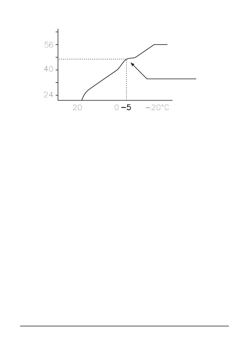
Sometimes, at outdoor temperatures between -5°C and +5°C, part of the heat curve may
need adjusting if the indoor temperature is not constant. For this reason, the control system
includes a function adjusting the curve at three outdoor temperatures: -5°C, 0°C and +5°C.
If, for example, the outdoor temperature is -5°C, the supply temperature will change gradu-
ally between 0°C and -10°C, maximum adjustment being reached at -5°C. The figure below
displays the adjusted CURVE -5. The adjustment can be seen on the graph in the form of a
bump.
Supply temperature
Outdoor temperature
Maximum supply tem-
perature
Danfoss – 13
VUBMA202
Figure 8: The adjusted curve at -5°C
You can choose to adjust the heat curve individually at three specified outdoor temperatures:
-5°C, 0°C and +5°C. The supply temperature can be changed by plus/minus 5 degrees.
HEATSTOP
The HEATSTOP function automatically stops all production of heat when the outdoor tem-
perature is equal to, or higher than, the value entered for heat-stop.
When the heat-stop function is activated, the circulation pump will be turned off - except
when hot water is being produced. The circulation pump will be "exercised" for 1 minute per
day. The factory set value for activating heat-stop is an outdoor temperature of 17°C. If the
heat-stop function is active, the outdoor temperature must drop 3°C when setting, before the
heat-stop stops.
MIN and MAX
The MIN and MAX values are the lowest, respectively highest set point values that are allowed
for the supply temperature.
Adjusting the minimum and maximum supply temperatures is particularly important if your
home has under floor heating.
If your house has under floor heating and parquet floors, the supply temperature must not
exceed the recommendations of the floor manufacturer. Otherwise there is a risk that the
parquet floors might be damaged. If you have under floor heating and stone tiles, the MIN
value should be 22-25°C, even in summer when no heating is required. Also remember that
the value for HEATSTOP needs adjusting upwards for summer heating. This is to achieve a
comfortable floor temperature.
If your house has a basement, the MIN value should be adjusted to a suitable temperature
for the basement in summer. A condition for maintaining the heat in the basement in the
summer is that all radiators have thermostat valves that switch off the heat in the rest of the
house. It is extremely important that the heating system in the house is trimmed correctly,
see the ”Trimming the heating system” section for further information. Also remember that
the value for HEATSTOP needs adjusting upwards for summer heating.
Supply temperature
Outdoor temperature
Local higher supply tem-
perature at -5°

Danfoss – 14 VUBMA202
TEMPERATURES
The heat pump can display a graph showing the history of the various sensors’ temperatures
and you can see how they have changed over 100 measurement points in time. The time
interval between the measurement points can be adjusted between one minute and one
hour, factory setting is one minute.
History is available for all sensors, but only the set value is shown in the display for the room
sensor. The integral value that may appear is the heating system’s energy balance.
INTEGRAL
The information below tells you how your heat pump works, there are no values that you as a
customer have to set.
The heat demand in the house depends on the season and weather conditions and is not
constant. The heat demand can be expressed as temperature difference over time and can be
calculated giving an integral value as a result (heat demand). To calculate the integral value,
the control computer uses several parameters.
A heat deficit is needed to start the heat pump, and there are two integral values, A1 and A2,
which start the compressor and auxiliary heater. During heat production, the deficit reduces
and when the heat pump stops, the inertia in the system causes a surplus of heat.
The integral value is a measurement of the surface under the time axis and is expressed in
degree minutes. The figure below shows the factory settings for the integral values that the
heat pump has. When the integral value has reached the set value for INTEGRAL A1, the
compressor starts and if the integral value does not drop but continues to rise, the auxiliary
heater starts when the integral value has reached the set value for INTEGRAL A2.
Figure 9: Starting and stopping heat pump operation based on integral values.
The integral value calculation stops during hot water production and during heat-stop.
Integral value calculation resumes two minutes after completed hot water production to give
the heating system time to stabilise the temperature.
Heat surplus
Integral
INTEGRAL A1
Heat surplus
Heating deficit
Compressor
start (-60)
INTEGRAL A2
INTEGRAL A1
INTEGRAL A2
Auxiliary heater
start (-660)
Compressor
stop (≥0)
Auxiliary heater
stop (latest at -60)
Auxiliary
heater
Compressor
No operation No operation
Compressor
start (-60)
Auxiliary heater
start (-660)
Auxiliary
heater
Compressor
Time
Heat pump operation
(Heat demand)

Danfoss – 15
VUBMA202
HYSTERESIS
The information below tells you how your heat pump works, there are no values that you as
a customer have to set.
In order to start the heat in advance during sudden changes of the heat demand, there is a
value, HYSTERESIS, which controls the difference between the actual supply temperature, t1
and the calculated supply temperature, t2. If the difference is the same or greater than the
set HYSTERESIS value (x), i.e. there is a heat demand, or the heat demand disappears, quicker
than the usual integral calculation, the integral value is forced to either the start value
INTEGRAL A1 or to the stop value 0°min.
Figure 10: Conditions for HYSTERESIS to force the integral value to change.
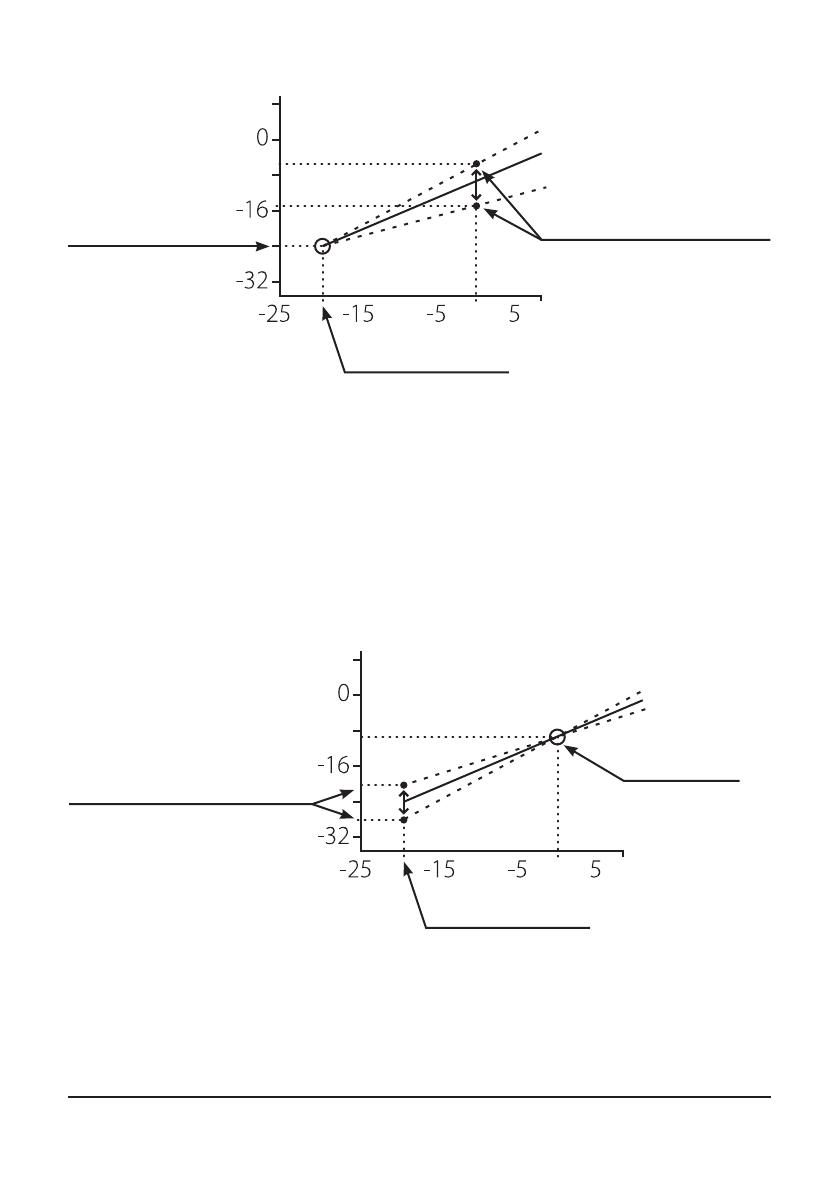
DEFR CURVE, defrosting curve for DHP-A, -AL
When defrosting the outdoor unit of DHP-A, -AL, the control computer makes a calculation
using a combination of the temperature on the incoming supply line and outdoor tempera-
ture.
What guides the calculation is a linear defrosting curve that can be set so that the heat
pump and outdoor unit work optimally. The setting of three different values can be changed:
OUTDOOR STOP, DEFR CURVE 0 and DEFR CURVE [value OUTDOOR STOP ]. The defrosting
sequence starts when the temperature of the incoming brine line reaches the outdoor tem-
perature somewhere along the set defrosting curve. The control computer shows the value
for DEFR CURVE 0 and DEFR CURVE [value OUTDOOR STOP] by means of a graph in the dis-
play.
HYSTERESIS
(∆t) ≥ x
Compressor start
(-60)
Compressor stop
(0)
t1
t2
HYSTERESIS
(∆t) ≥ x
TIME
INTEGRAL
SUPPLY TEMP.
Danfoss – 16 VUBMA202
Figure 11: Graph that shows how the value for DEFR CURVE 0 can be set.
The value for OUTDOOR STOP that is set means that outdoor unit is no longer used for heat-
ing or hot water production if the outdoor temperature is the same as or lower than the
value. Heating and hot water production then occurs with the help of the auxiliary heater.
The value for DEFR CURVE 0 is the temperature that the input brine return has when a
defrost must start at outdoor temperature 0°C.
In the corresponding way the value for DEFR CURVE [value OUTDOOR STOP] is the tempera-
ture that the incoming brine return has when a defrost should start at the set outdoor tem-
perature for OUTDOOR STOP.
Figure 12: Graph that shows how the value for DEFR CURVE [OUTDOOR STOP] can be set.
These three settings together create the defrosting curve and all three values have an effect
on when the defrosting will start.
Temperature, input brine
pipe
Outdoor temperature
Adjustable interval for incoming brine
temperature at 0°C outdoor tempera-
ture is -5°C to -15°C
Set value for OUTDOOR STOP
Set value for
DEFR CURVE
[value OUTDOOR STOP]
Temperature, input brine
pipe
Outdoor temperature
AT the outdoor temperature for
OUTDOOR STOP, the adjustable range for
DEFR CURVE [value UTESTOPP]
is -1°C to -8°C lower than OUTDOOR STOP
Set value for OUTDOOR STOP
Set value for
DEFR CURVE 0

Danfoss – 17
VUBMA202
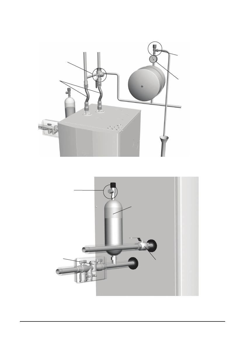
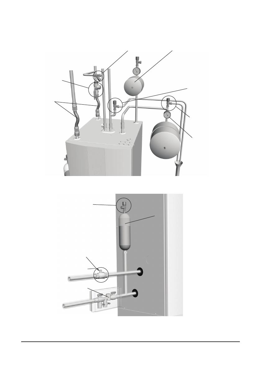
2.8 Installation principle, DHP-H
The image shows the principles of a piping installation with all components.
Figure 13: Principle solution for a piping installation.
Figure 14: Principle solution for a brine installation.
Safety valve
Pressure
gauge
Filler tap
HW = Hot water
CW = Cold water
Exp = Expansion
HW
Expansion
tank
To
outlet
Supply pipe
Return pipe
Safety valve, 9 bar
cold water
CW
Exp
Shut-off cock and
strainer
Flexible hoses
Safety valve, 1,5 bar
Bleed and expan-
sion tank
Filler cock incl.
strainer
Shut-off valve
Strainer
Brine in
Brine out

Danfoss – 18 VUBMA202
2.8 Installation principle, DHP-C
The image shows the principles of a piping installation with all components.
Figure 13: Principle solution for a piping installation.
Figure 14: Principle solution for a brine installation.
Safety valve
Pressure
gauge
Filler tap
HW = Hot water
CW = Cold water
Exp = Expansion
HW
Expansion
tank
To
outlet
Supply pipe
Return pipe
Safety valve, 9 bar
cold water
CW
Exp
Shut-off cock and
strainer
Flexible hoses
Safety valve, 1,5 bar
Bleed and expan-
sion tank
Filler cock incl.
strainer
Strainer
Brine in
Brine out
Shut-off valve
Danfoss – 19
VUBMA202
2.9 Installation principle, DHP-L
The image shows the principles of a piping installation with all components.
Figure 15: Principle solution for a piping installation.
Figure 16: Principle solution for a brine installation.
Supply pipe Return pipe
Connection to any
water heaters
Flexible hoses
Shut-off cock and
strainer
To
outlet
Expansion
tank
Pressure
gauge
Safety valve
Safety valve, 1,5 bar
Bleed and expan-
sion tank
Filler cock incl.
strainer
Shut-off valve
Strainer
Brine in
Brine out
Danfoss – 20 VUBMA202
2.10 Installation principle, DHP-A
The image shows the principles of a piping installation with all components.
Figure 17: Principle solution for a piping installation.
Figure 18: Principle solution for a brine installation.
Location of expansion tank,
manometer and safety valve (1.5
bar) at pressurised brine circuit
when the outdoor unit is positioned
higher than the heat pump.
Safety valve
Pressure
gauge
Filler tap
HW = Hot water
CW = Cold water
Exp = Expansion
Exp BRINE = Expansion
brine circuit
HW
Expansion
tank
To
outlet
Supply pipe
Return pipe
Safety valve, 9 bar
cold water
CW
Exp
Shut-off cock and
strainer
Exp BRINE
Flexible hoses
Safety valve, 1.5 bar
Location of the bleed and expan-
sion tank when the outdoor unit
is located at the same level or
lower than the heat pump.
NOTE! The fluid level in the tank
must be above the highest point
of the outdoor unit.
Filler cock incl.
strainer
Shut-off valve
Strainer
Brine in
Brine out
/