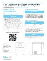
2 Dispenser and Ice Machine 230 V/50 Hz and 220 V/60 Hz
Contents
Welcome ......................................................................................3
Before You Begin ...............................................................................3
Important Safety Information .....................................................................4
Specications .................................................................................4
Dimensions .................................................................................4
Ambient Information ..........................................................................4
Plumbing ...................................................................................4
Specications .................................................................................5
Water .....................................................................................5
Clearances .................................................................................5
Electrical ...................................................................................5
Refrigeration ................................................................................5
Heat Rejection ..............................................................................5
_7 Series Detailed Drawing ....................................................................6
_15 Series Detailed Drawing ...................................................................7
Installation ....................................................................................8
Countertop Installation ........................................................................8
Freestanding Installation .......................................................................9
Maintenance/Cleaning Mode ....................................................................12
Accessing Internal Components .................................................................12
Filter Display Indicator Activation ................................................................13
NSF-approved Cleaning and Sanitizing Procedure ..................................................14
Service ......................................................................................15
LED Indicator Description .....................................................................15
Evaporator Disassembly ......................................................................16
Evaporator Assembly ........................................................................19
Water Feed Schematic .......................................................................23
Bin Melt Water/Evaporator Feed/Clean Out System Schematic .......................................24
Vent System Schematic ......................................................................24
Refrigeration Schematic ......................................................................25
Condenser Fan Motor Removal (_7 Series Shown) ................................................26
User Interface Display Identication .............................................................27
Electrical Wiring Diagram .....................................................................29
Parts ........................................................................................30
_7 Series Exterior ...........................................................................30
_7 Series Interior ...........................................................................32
Parts ........................................................................................34
_15 Series Exterior ..........................................................................34
_15 Series Interior ..........................................................................36
_7 Series Bin Assembly ......................................................................38
_15 Series Bin Assembly .....................................................................40
Evaporator Assembly ........................................................................42
Base Stand ................................................................................44