Page is loading ...

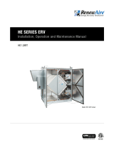
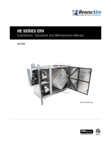
CA4XIN shown
CA2XIN
CA3XIN
CA4XIN
CA SERIES ERV
Installation, Operation and Maintenance Manual

1.800.627.44992
CA-Series Indoor
ERV
RISK OF FIRE, ELECTRIC SHOCK, OR INJURY.
OBSERVE ALL CODES AND THE FOLLOWING:
1. Before serviceing or cleaning the unit, switch power off at
system disconnect switch or service panel and lock-out/
tag-out to prevent power from being switched on acciden-
tally. More than one disconnect switch may be required to
de-energize the system for servicing.
2. This installation manual shows the suggested installation
method. Additional measures may be required by local
codes and standards.
3. Installation work and electrical wiring must be done by
qualified professional(s) in accordance with all applicable
codes, standards, and licensing requirements.
4. Any structural alterations necessary for installation must
comply with all applicable building, health, and safety code
requirements.
5. Electrical equipment connected to this unit must be properly
grounded.
6. Sufficient air is needed for proper combustion and exhaust-
ing of gases through the flue (chimney) of fuel burning
equipment that might be installed in the area affected by
this equipment. If this unit is exhausting air from a space in
which chimney-vented fuel burning equipment is located,
take steps to assure that combustion air supply require-
ments of applicable codes and standards.
7. Use the unit only in the manner intended by the manufac-
turer. If you have questions, contact the manufacturer.
8. This unit is intended for general ventilating only. Do not use
to exhaust hazardous or explosive materials and vapors. Do
not connect this unit to range hoods, fume hoods, or collec-
tion systems for toxics.
9. This unit must be properly ducted to the outdoors. Outside
air inlets must not be located where air may be contami-
nated, for example by vehicle or appliance exhausts.
WARNING
Maximum Differential Pressure
The maximum pressure differential between the two air-
streams shound not exceed 4 inches (H2O).
CAUTION
Danger of carbon monoxide poisoning! Outside air intake
should be 10' (minimum) away from sources of carbon mon-
oxide or other toxic gases such as chimneys, furnace, or water
heater exhausts.
Do not locate outside air intake where vehicles may be ser-
viced or left idling. Do not locate the outside air intake inside
an enclosed space.
WARNING
DANGER OF DAMAGE DUE TO CONDENSATION IN OR ON
DUCTS TO OUTSIDE.
Both ducts connecting the unit to the outside must be insulated
with sealed vapor barriers inside and out to prevent condensa-
tion and/or freezing inside the insulation or on the duct surface.
CAUTION
ALWAYS DISCONNECT POWER SOURCE BEFORE SERVICING,
TO ENSURE NO AIR FLOW IN THE SYSTEM.
High volume of air in the case when operating! If you open
an access door when the system is running, you may be
exposed to as much as 8,000 CFM! Severe eye injury could
result!
WARNING
Install clean filters prior to airflow testing.
Select the static pressure test points with care—try several
locations and pick the most stable and representative sampling
point.
CAUTION
Never locate the outside air inlet inside a structure.
CAUTION
Filters must be used or the energy exchanger core will become
blocked by dust and the unit will not do its job. In extreme
cases components may be damaged.
CAUTION
Do Not Wash the Energy Exchange Core.
Keep it away from water or fire to avoid damaging it. Always
handle the core carefully.
CAUTION

31.800.627.4499
CA-Series Indoor ERV
SAVE THIS MANUAL
UNIT INFORMATION
Record information as shown below.
In the unlikely event that factory assistance is ever required, information located on the unit
label will be needed.
Locate the RenewAire unit label found on the outside of the unit.
NOTE: This information is for purposes of identifying the unit-specific option data from the
Option Code.
UNIT INFORMATION
UNIT LABEL (TYPICAL)
C -X - -- -I - -A - -J - --N -
OPTION CODE:
SERIAL NUMBER:
SO #:
OWNER INFORMATION
NOTE: This page
is to be completed
by the installing
contractor. The completed
document is to be turned
over to the owner after
start-up.
N

1.800.627.44994
RENEWAIRE.COM 1.800.627.4499
4
SPECIFICATIONS & DIMENSIONS
Specifi cations may be subject to change without notice.
INDOOR UNIT
Modular Cabinets
Insulation:
One inch, high density, FSK faced, fi berglass
Options:
Double wall construction
Exterior paint - white, custom colors
Accessories:
Filters - MERV 13, 2" (shipped loose)
SPECIFICATIONS
Ventilation Type:
Static plate, heat and humidity transfer
Standard Features:
Insulated sheet metal cabinets with energy
exchange cores and fi lters.
Individual CA-Series units or stacks of units can be
built into larger air handling systems.
Blower not included and must be specifi ed to meet
job requirements.
CORE PERFORMANCE AIRFLOW PERFORMANCE
Description CA2XIN CA3XIN CA4XIN
Typical Airfl ow
Range CFM 500-2,200 750-3,300 1,000-4,400
AHRI 1060 Certifi ed Core Two L125-G5 Three L125-G5 Four L125-G5
Unit Dimensions
& Weight
36" L x 42 1/2" W x 35" H
225-304 lbs.
36" L x 62 1/4" W x 35" H
325-430 lbs.
36" L x 81 3/4" W x 35" H
400-531 lbs.
Max. Shipping Dimensions
& Weight (on pallet)
62" L x 42" W x 40" H
350 lbs.
70" L x 47" W x 40" H
500 lbs.
96" L x 47" W x 40" H
620 lbs.
Filters: MERV 8:
20" x 20" x 2" Total qty. 4 Total qty. 6 Total qty. 8
dPRatingsCA‐IN2015.xlsx dPCA2X‐4XIN
0.0
0.5
1.0
1.5
0 1000 2000 3000 4000
Static Presure
Drop (in.w.g)
Airflow (CFM)
Note: Airfl ow performance includes effect of clean,
standard fi lter supplied with unit.
CA‐RTFlowRatingsAnalysis.xlsx Chart
0.0
0.5
1.0
1.5
2.0
0 1000 2000 3000 4000
Static Presure
Drop (in.w.g)
Airflow (CFM)
ThermalPerformanceRatingsG52015.2.xlsx 2Cores(IOM)
30%
50%
70%
90%
500 1000 1500 2000
Effectiveness(%)
Airflow(CFM)
CA2XIN
ThermalPerformanceRatingsG52015.2.xlsx 3Cores(IOM)
30%
50%
70%
90%
500 1000 1500 2000 2500 3000 3500
Effectiveness(%)
Airflow(CFM)
CA3XIN
ThermalPerformanceRatingsG52015.2.xlsx 4Cores(IOM)
30%
50%
70%
90%
1000 2000 3000 4000
Effectiveness(%)
Airflow(CFM)
CA4XIN
At AHRI 1060 standard conditions.
See all AHRI certifi ed ratings at www.ahrinet.org.
INDOORCA Energy Recovery Module
Download specification at:
renewaire.com/specifications
APPLICATION
(800) 627-4499 • Fax: (608) 221-2824
66
Applied Products
Similar designs can use PA-Series arrays.
(PA-Series provide top service access and an “over-under” airow arrangement.)
Central Air Handler using CA4X and exhaust and make-up air blowers.
(CA-Series provide side service access and a “side-by-side” airow arrangement.)
Installation Example
Some ventilation projects require more exibility than packaged ERVs allow. RenewAire offers both
indoor and outdoor cabinets of ERV cores in insulated sheet metal cabinets with MERV 8 or MERV 13
lters. Realize your energy-efciency goals with RenewAire’s Applied Products family of ERVs.
• Cost effective energy recovery for virtually any air handling system
• Complete exibility in locating eld supplied blowers
– great for acoustically sensitive applications
• AHRI certied performance data for efciency and cross leakage
• UL tested ammability and smoke generation that meets
NFPA 90A and 90B test standards for commercial applications
• Ten year core performance warranty
CA-Series
• Cores stacked side-by-side horizontally
• Each cabinet contains 2, 3, or 4 energy exchange cores
• Indoor (IN) and outdoor (RT) models available
• Indoor cabinets can be stacked up to ve high (with support structure)
accommodating up to 20,000 CFM (NOTE: outdoor cabinets cannot be stacked)
• Side access service door(s)
• Double wall construction optional
PA-Series
• Cores stacked vertically 3 or 4 cores high
• Each cabinet contains 6, 8, 9, or 12 energy exchange cores
• Indoor (IN) models only
• Indoor cabinets can be joined together lengthwise to accommodate unlimited airows
• Top access service panels
• Shipped knock down (K) or factory assembled (A)
- Each component ts through 3 foot swing door. Ideal for tight applications.
CA4X
CA-SERIES
34 7/8" Case
36" Overall
FRONT VIEW
Note: Pleated, disposable
20" X 20" X 2" filters are
provided for installation
and are interchangeable
based on your airflow
path requirements. Filters
are to be mounted
upstream to the core in
the direction of airflow
entering the unit.
42 3/8" Overall
34 7/8" Overall
LEFT VIEW
42 3/8" Case
1 1/8"
Typ.
5 3/4"
Typ.
1 1/8"
Typ.
5 3/4"
Typ.
34 7/8" Case
RIGHT VIEW
14 1/8" X 14 1/8"
Typ.
33 7/8" Minimum
Service Area Typ.
35" Minimum
Service Area Typ.
TOP VIEW
Door
Swing
Door
Swing
Model: CA2XIN
Drawing Type: Unit Dimension
Version: MAY16
ABBREVIATION
EA: Exhaust Air to outside
OA: Outside Air intake
RA: Room Air to be exhausted
FA: Fresh Air to inside
INSTALLATION ORIENTATION
Unit may be installed in any
orientation.
NOTE:
1. UNLESS OTHERWISE SPECIFIED,
DIMENSIONS ARE ROUNDED TO THE
NEAREST EIGHTH OF AN INCH.
2. SPECIFICATIONS MAY BE SUBJECT
TO CHANGE WITHOUT NOTICE.
CA2XIN Energy Recovery Module
AIRFLOW CONFIGURATION
Available as shown in dimension drawing.
UNIT MOUNTING & APPLICATION
Can be mounted in any orientation. RA/EA airstream
can be switched with OA/FA airstream. Can be
stacked three high.

51.800.627.4499
FOR THE MOST COMPLETE AND CURRENT INFORMATION VISIT RENEWAIRE.COM 5
SPECIFICATIONS & DIMENSIONS
Specifi cations may be subject to change without notice.
INDOOR UNIT
Modular Cabinets
Insulation:
One inch, high density, FSK faced, fi berglass
Options:
Double wall construction
Exterior paint - white, custom colors
Accessories:
Filters - MERV 13, 2" (shipped loose)
SPECIFICATIONS
Ventilation Type:
Static plate, heat and humidity transfer
Standard Features:
Insulated sheet metal cabinets with energy
exchange cores and fi lters.
Individual CA-Series units or stacks of units can be
built into larger air handling systems.
Blower not included and must be specifi ed to meet
job requirements.
CORE PERFORMANCE AIRFLOW PERFORMANCE
Description CA2XIN CA3XIN CA4XIN
Typical Airfl ow
Range CFM 500-2,200 750-3,300 1,000-4,400
AHRI 1060 Certifi ed Core Two L125-G5 Three L125-G5 Four L125-G5
Unit Dimensions
& Weight
36" L x 42 1/2" W x 35" H
225-304 lbs.
36" L x 62 1/4" W x 35" H
325-430 lbs.
36" L x 81 3/4" W x 35" H
400-531 lbs.
Max. Shipping Dimensions
& Weight (on pallet)
62" L x 42" W x 40" H
350 lbs.
70" L x 47" W x 40" H
500 lbs.
96" L x 47" W x 40" H
620 lbs.
Filters: MERV 8:
20" x 20" x 2" Total qty. 4 Total qty. 6 Total qty. 8
dPRatingsCA‐IN2015.xlsx dPCA2X‐4XIN
0.0
0.5
1.0
1.5
0 1000 2000 3000 4000
Static Presure
Drop (in.w.g)
Airflow (CFM)
Note: Airfl ow performance includes effect of clean,
standard fi lter supplied with unit.
CA‐RTFlowRatingsAnalysis.xlsx Chart
0.0
0.5
1.0
1.5
2.0
0 1000 2000 3000 4000
Static Presure
Drop (in.w.g)
Airflow (CFM)
ThermalPerformanceRatingsG52015.2.xlsx 2Cores(IOM)
30%
50%
70%
90%
500 1000 1500 2000
Effectiveness(%)
Airflow(CFM)
CA2XIN
ThermalPerformanceRatingsG52015.2.xlsx 3Cores(IOM)
30%
50%
70%
90%
500 1000 1500 2000 2500 3000 3500
Effectiveness(%)
Airflow(CFM)
CA3XIN
ThermalPerformanceRatingsG52015.2.xlsx 4Cores(IOM)
30%
50%
70%
90%
1000 2000 3000 4000
Effectiveness(%)
Airflow(CFM)
CA4XIN
At AHRI 1060 standard conditions.
See all AHRI certifi ed ratings at www.ahrinet.org.
INDOORCA Energy Recovery Module
Download specification at:
renewaire.com/specifications
APPLICATION
(800) 627-4499 • Fax: (608) 221-2824
66
Applied Products
Similar designs can use PA-Series arrays.
(PA-Series provide top service access and an “over-under” airow arrangement.)
Central Air Handler using CA4X and exhaust and make-up air blowers.
(CA-Series provide side service access and a “side-by-side” airow arrangement.)
Installation Example
Some ventilation projects require more exibility than packaged ERVs allow. RenewAire offers both
indoor and outdoor cabinets of ERV cores in insulated sheet metal cabinets with MERV 8 or MERV 13
lters. Realize your energy-efciency goals with RenewAire’s Applied Products family of ERVs.
• Cost effective energy recovery for virtually any air handling system
• Complete exibility in locating eld supplied blowers
– great for acoustically sensitive applications
• AHRI certied performance data for efciency and cross leakage
• UL tested ammability and smoke generation that meets
NFPA 90A and 90B test standards for commercial applications
• Ten year core performance warranty
CA-Series
• Cores stacked side-by-side horizontally
• Each cabinet contains 2, 3, or 4 energy exchange cores
• Indoor (IN) and outdoor (RT) models available
• Indoor cabinets can be stacked up to ve high (with support structure)
accommodating up to 20,000 CFM (NOTE: outdoor cabinets cannot be stacked)
• Side access service door(s)
• Double wall construction optional
PA-Series
• Cores stacked vertically 3 or 4 cores high
• Each cabinet contains 6, 8, 9, or 12 energy exchange cores
• Indoor (IN) models only
• Indoor cabinets can be joined together lengthwise to accommodate unlimited airows
• Top access service panels
• Shipped knock down (K) or factory assembled (A)
- Each component ts through 3 foot swing door. Ideal for tight applications.
CA4X
CA-SERIES
34 7/8" Case
36" Overall
FRONT VIEW
Note: Pleated, disposable
20" X 20" X 2" filters are
provided for installation
and are interchangeable
based on your airflow
path requirements. Filters
are to be mounted
upstream to the core in
the direction of airflow
entering the unit.
42 3/8" Overall
34 7/8" Overall
LEFT VIEW
42 3/8" Case
1 1/8"
Typ.
5 3/4"
Typ.
1 1/8"
Typ.
5 3/4"
Typ.
34 7/8" Case
RIGHT VIEW
14 1/8" X 14 1/8"
Typ.
33 7/8" Minimum
Service Area Typ.
35" Minimum
Service Area Typ.
TOP VIEW
Door
Swing
Door
Swing
Model: CA2XIN
Drawing Type: Unit Dimension
Version: MAY16
ABBREVIATION
EA: Exhaust Air to outside
OA: Outside Air intake
RA: Room Air to be exhausted
FA: Fresh Air to inside
INSTALLATION ORIENTATION
Unit may be installed in any
orientation.
NOTE:
1. UNLESS OTHERWISE SPECIFIED,
DIMENSIONS ARE ROUNDED TO THE
NEAREST EIGHTH OF AN INCH.
2. SPECIFICATIONS MAY BE SUBJECT
TO CHANGE WITHOUT NOTICE.
CA2XIN Energy Recovery Module
AIRFLOW CONFIGURATION
Available as shown in dimension drawing.
UNIT MOUNTING & APPLICATION
Can be mounted in any orientation. RA/EA airstream
can be switched with OA/FA airstream. Can be
stacked three high.

1.800.627.44996
RENEWAIRE.COM 1.800.627.4499
6
SPECIFICATIONS & DIMENSIONS
34 3/4" Case
36" Overall
FRONT VIEW
Note: Pleated, disposable
20" X 20" X 2" filters are
provided for installation
and are interchangeable
based on your airflow path
requirements. Filters are to
be mounted upstream to
the core in the direction of
airflow entering the unit.
34 7/8" Overall
62" Overall
LEFT VIEW
1 1/8"
Typ.
5 3/4"
Typ.
1 1/8"
Typ.
5 3/4"
Typ.
62" Case
34 7/8" Case
RIGHT VIEW
14 1/8" X 24 1/8"
Typ.
33 7/8" Minimum
Service Area Typ.
35" Minimum
Service Area Typ.
TOP VIEW
Door
Swing
Door
Swing
Model: CA3XIN
Drawing Type: Unit Dimension
Version: MAY16
ABBREVIATION
EA: Exhaust Air to outside
OA: Outside Air intake
RA: Room Air to be exhausted
FA: Fresh Air to inside
INSTALLATION ORIENTATION
Unit may be installed in any
orientation.
NOTE:
1. UNLESS OTHERWISE SPECIFIED,
DIMENSIONS ARE ROUNDED TO THE
NEAREST EIGHTH OF AN INCH.
2. SPECIFICATIONS MAY BE SUBJECT
TO CHANGE WITHOUT NOTICE.
CA3XIN Energy Recovery Module
AIRFLOW CONFIGURATION
Available as shown in dimension drawing.
UNIT MOUNTING & APPLICATION
Can be mounted in any orientation. RA/EA airstream
can be switched with OA/FA airstream. Can be
stacked three high.
CA-SERIES
34 7/8"
Case
36"
Overall
FRONT VIEW
Note: Pleated, disposable
20" X 20" X 2" filters are
provided for installation
and are interchangeable
based on your airflow path
requirements. Filters are to
be mounted upstream to
the core in the direction of
airflow entering the unit.
34 7/8" Overall
81 5/8" Overall
LEFT VIEW
81 5/8" Case
7 5/8" Typ.
1 1/8" Typ.
7 5/8"
Typ.
1 1/8"
Typ.
34 7/8"
Case
RIGHT VIEW
14 1/8" X 32 1/8"
Typ.
33 7/8" Minimum
Service Area Typ.
35" Minimum
Service Area Typ.
TOP VIEW
Door
Swing
Door
Swing
Model: CA4XIN
Drawing Type: Unit Dimension
Version: MAY16
ABBREVIATION
EA: Exhaust Air to outside
OA: Outside Air intake
RA: Room Air to be exhausted
FA: Fresh Air to inside
INSTALLATION ORIENTATION
Unit may be installed in any
orientation.
NOTE:
1. UNLESS OTHERWISE SPECIFIED,
DIMENSIONS ARE ROUNDED TO THE
NEAREST EIGHTH OF AN INCH.
2. SPECIFICATIONS MAY BE SUBJECT
TO CHANGE WITHOUT NOTICE.
CA4XIN Energy Recovery Module
AIRFLOW CONFIGURATION
Available as shown in dimension drawing.
UNIT MOUNTING & APPLICATION
Can be mounted in any orientation. RA/EA airstream
can be switched with OA/FA airstream. Can be
stacked three high.

71.800.627.4499
FOR THE MOST COMPLETE AND CURRENT INFORMATION VISIT RENEWAIRE.COM 7
SPECIFICATIONS & DIMENSIONS
34 3/4" Case
36" Overall
FRONT VIEW
Note: Pleated, disposable
20" X 20" X 2" filters are
provided for installation
and are interchangeable
based on your airflow path
requirements. Filters are to
be mounted upstream to
the core in the direction of
airflow entering the unit.
34 7/8" Overall
62" Overall
LEFT VIEW
1 1/8"
Typ.
5 3/4"
Typ.
1 1/8"
Typ.
5 3/4"
Typ.
62" Case
34 7/8" Case
RIGHT VIEW
14 1/8" X 24 1/8"
Typ.
33 7/8" Minimum
Service Area Typ.
35" Minimum
Service Area Typ.
TOP VIEW
Door
Swing
Door
Swing
Model: CA3XIN
Drawing Type: Unit Dimension
Version: MAY16
ABBREVIATION
EA: Exhaust Air to outside
OA: Outside Air intake
RA: Room Air to be exhausted
FA: Fresh Air to inside
INSTALLATION ORIENTATION
Unit may be installed in any
orientation.
NOTE:
1. UNLESS OTHERWISE SPECIFIED,
DIMENSIONS ARE ROUNDED TO THE
NEAREST EIGHTH OF AN INCH.
2. SPECIFICATIONS MAY BE SUBJECT
TO CHANGE WITHOUT NOTICE.
CA3XIN Energy Recovery Module
AIRFLOW CONFIGURATION
Available as shown in dimension drawing.
UNIT MOUNTING & APPLICATION
Can be mounted in any orientation. RA/EA airstream
can be switched with OA/FA airstream. Can be
stacked three high.
CA-SERIES
34 7/8"
Case
36"
Overall
FRONT VIEW
Note: Pleated, disposable
20" X 20" X 2" filters are
provided for installation
and are interchangeable
based on your airflow path
requirements. Filters are to
be mounted upstream to
the core in the direction of
airflow entering the unit.
34 7/8" Overall
81 5/8" Overall
LEFT VIEW
81 5/8" Case
7 5/8" Typ.
1 1/8" Typ.
7 5/8"
Typ.
1 1/8"
Typ.
34 7/8"
Case
RIGHT VIEW
14 1/8" X 32 1/8"
Typ.
33 7/8" Minimum
Service Area Typ.
35" Minimum
Service Area Typ.
TOP VIEW
Door
Swing
Door
Swing
Model: CA4XIN
Drawing Type: Unit Dimension
Version: MAY16
ABBREVIATION
EA: Exhaust Air to outside
OA: Outside Air intake
RA: Room Air to be exhausted
FA: Fresh Air to inside
INSTALLATION ORIENTATION
Unit may be installed in any
orientation.
NOTE:
1. UNLESS OTHERWISE SPECIFIED,
DIMENSIONS ARE ROUNDED TO THE
NEAREST EIGHTH OF AN INCH.
2. SPECIFICATIONS MAY BE SUBJECT
TO CHANGE WITHOUT NOTICE.
CA4XIN Energy Recovery Module
AIRFLOW CONFIGURATION
Available as shown in dimension drawing.
UNIT MOUNTING & APPLICATION
Can be mounted in any orientation. RA/EA airstream
can be switched with OA/FA airstream. Can be
stacked three high.

1.800.627.44998
CA-Series Indoor
ERV
1.0 OVERVIEW 10
1.1 CA-SERIES INDOOR OPERATION ........................... 10
1.2 APPLICATION GUILDLINES .....................................10
1.2.1 Purpose of CA-Series Indoor Cabinets ...............................10
1.2.2 General Layout ................................................................. 10
1.2.3 Stacked Installations......................................................... 11
1.2.4 Location ........................................................................... 11
1.3 SERVICE ACCESS ..................................................11
1.3.1 Service Access ................................................................. 11
1.3.2 Connection to HVAC System .............................................. 11
2.0 INSTALLATION 12
2.1 BLOWER ORIENTATION .........................................12
2.1.1 Push-Push and Pull-Pull—Recomended ............................12
2.1.2 OA Push–EA Pull—Use with Caution ................................. 12
2.2 BLOWER SIZING ...................................................13
2.3 STATIC PRESSURE DROP THROUGH THE CABINET .13
2.4 STACKED INSTALLATIONS .....................................14
2.5 SPECIAL CONSIDERATIONS FOR OUTSIDE AIR AND
EXHAUST AIR DUCTS ..................................................15
3.0 OPERATION 16
3.1 PRINCIPAL OF OPERATION ....................................16
TABLE OF CONTENTS
TABLE OF ILLUSTRATIONS
Figure 1.2.0 Opposide Side Airflow Entries ............................................................................................................................................... 10
Figure 1.2.1 Same Side Airflow Entries ..................................................................................................................................................... 10
Figure 1.3.0 CA-Series Indoor Cabinet Application Example ...................................................................................................................... 11
Figure 2.1.0 “Push-Push” Blower Orientation ........................................................................................................................................... 12
Figure 2.1.1 “Pull-Pull” Blower Orientation ............................................................................................................................................... 12
Figure 2.1.2 “OA Push- EA Pull” Blower Orientation .................................................................................................................................. 12
Figure 2.1.3 “RA Push- FA Pull” Blower Orientation Not Recommended ..................................................................................................... 12
Figure 2.3.0 Rated Pressure Drop Through Cabinet .................................................................................................................................. 13
Figure 2.4.0 Stack and Secure Cabinets ................................................................................................................................................... 14
Figure 2.4.1 Attach Flanges ..................................................................................................................................................................... 14
Figure 2.4.2 Flange Sizes for use in Stacked Installations ......................................................................................................................... 14
Figure 2.4.3 Connect Ductwork ................................................................................................................................................................ 15
Figure 4.3.0 CA-2X Initial Pressure Drop 20" x 20" MERV 8 Filters ........................................................................................................... 18
Figure 4.3.1 CA-3X Initial Pressure Drop 20" x 20" MERV 8 Filters ........................................................................................................... 19
Figure 4.3.2 CA-4X Initial Pressure Drop 20" x 20" MERV 8 Filters ........................................................................................................... 19
3.2 CHECKING THE OPERATION OF THE CA-SERIES
INDOOR CABINETS .....................................................16
3.2.1 Airflow–General................................................................16
3.3 ENERGY EXCHANGE .............................................. 16
3.4 OPERATING CONTROLS ......................................... 16
3.5 CONTINUOUS OPERATION .....................................16
3.6 OPERATION IN EXTREME COLD WEATHER .............16
3.7 FIELD MEASUREMENT OF AIRFLOW THROUGH
CORES .......................................................................17
4.0 MAINTENANCE 17
4.1 CHANGING THE FILTERS .......................................17
4.2 CLEAN THE ENERGY EXCHANGE CORE ..................18
4.3 FILTERS ...............................................................18
4.3.1 Filter Specifications ..........................................................18
4.3.2 Filter Resistance ...............................................................18
5.0 FACTORY ASSISTANCE 19

91.800.627.4499
CA-Series Indoor ERV
CONFIGURATION CODE
MODEL NUMBER
Model
1 2 3 4 5 6 7 8 9 10 11 12 13 14 15 16 17 18 19 20 21 22 23 24 25
J - -
DIGIT NUMBER
Digits 1 - 5:
*NOTES:
Digit 6 "J" = G5 Core Type Digits 9-10 and 12-23 are not used in these models.
Other Options
Digit 24:
"-" = None
"X" = Custom Unit
Safety Listing
Digit 25:
"N" = Non-Listed
"CA-2X" = Cabinet Applied 2 Cores
"CA-3X" = Cabinet Applied 3 Cores
"CA-4X" = Cabinet Applied 4 Cores
---- ------ N
Wall Type
Digit 11:
"S" = Single
"D" = Double
CA-IN--
CA INDOOR APPLIED PRODUCT CONFIGURATION CODE

1.800.627.449910
CA-Series Indoor
ERV
OVERVIEW
NOTE: Filters
are placed at the
INLET FACE of the
energy exchange core.
OA = Outside Air into unit.
RA = Return Air into unit.
FA = Fresh Air to inside.
EA = Exhaust Air to out-
side.
Never locate the outside air
inlet inside a structure.
CAUTION 1.0 OVERVIEW
1.1 CA-SERIES INDOOR OPERATION
The CA-Series Indoor cabinets have one basic purpose: to transfer heating or cooling energy
from an exhaust airstream to a fresh airstream.
The CA-Series Indoor cabinets operate with no moving parts. The cores in the modules will
transfer energy between the two airstreams as long as the two system blowers are moving air
through the module. (These blowers are separate from the cabinets).
1.2 APPLICATION GUIDELINES
1.2.1 Purpose of CA-Series Indoor Cabinets
The CA-Series Indoor cabinet(s) are modular cases with 2, 3, or 4 energy recovery cores. The
cabinets may be installed individually, or may be stacked and manifolded for larger-capacity
installations. A variety of duct connection configurations are possible. Disposable filters are
provided; they are of a common size and can easily be replaced.
1.2.2 General Layout
The CA-Series Indoor cabinet(s) are used to transfer energy from exhaust air leaving a building,
into fresh air being brought in from the outside for ventilation. By recoverying energy from the
exhaust airstream, the benefits of ventilation can be enjoyed without the full energy cost to
condition the outside air.
The CA-Series Indoor cabinet(s) do not contain blowers. Therefore, two blowers must be
installed as part of the system. Several ducts must also be installed.
FIGURE 1.2.0 OPPOSITE SIDE AIRFLOW ENTRIES
FIGURE 1.2.1 SAME SIDE AIRFLOW ENTRIES

111.800.627.4499
CA-Series Indoor ERV
OVERVIEW
1.2.3 Stacked Installations
When the installation requires more airflow than a single CA-Series Indoor cabinet can handle,
up to three cabinets can be stacked and manifolded.
1.2.4 Location
The CA-Series Indoor cabinet is designed for installation in a sheltered location, out of the
weather. The ideal location for the CA-Series Indoor cabinet is central to the inside duct runs,
and close to both the exhaust air duct (to the outside) and the fresh air duct (from the outside).
1.3 SERVICE ACCESS
1.3.1 Service Access
Install the ERV where you can remove the door for cleaning the core and filter. Although there is
no electrical connection to the cabinet(s), there should be a nearby system disconnect switch,
so service people can shut off the blowers connect to the system when changing filters.
1.3.2 Connection to the HVAC System
In most cases, one or two ducts connect the CA-Series Indoor cabinet to the building’s ducted
HVAC system. A variety of connection approaches are possible, depending on the number of CA-
Series Indoor cabinets in the installation, purpose of the system, and available space.
Cabinets may be flipped and rotated to fit the job. Whatever orientation of the cabinet is
selected, the airstreams must cross, as shown below.
The filters must cover the INLET FACES of the cores. Filter racks are provided at each face to
handle all possible airflow configurations.
FIGURE 1.3.0 CA-SERIES INDOOR CABINET APPLICATION EXAMPLE

1.800.627.449912
CA-Series Indoor
ERV
NOTE: This bypass
air volume is lower
than in most com-
peting technolo-
gies, such as heat wheels,
and even some other plate-
type exchangers.
2.1.2 OA Push–EA Pull—USE WITH CAUTION
This blower orientation causes the supply airstream to be at a much higher static pressure than
the exhaust airstream. This may result in bypass airflow, which must be evaluated in the design
process.
The advantage to this orientation is that both blowers are on the “outside” of the cabinets,
taking advatage of the acoustic attenuation offered by the cabinets. If outside airstream bypass
airflow occurs, it additionally insures no exhaust contaminants leak past seals into the fresh air.
The disadvantage to this orientation is that both blowers must be sized to provide the additional
bypass air, which in most cases is a needless waste of energy.
The higher overall static pressure tend to increase duct leakage.
FIGURE 2.1.2 “OA PUSH-EA PULL” BLOWER ORIENTATION
FIGURE 2.1.3 “RA PUSH-FA PULL” BLOWER ORIENTATION
NOT RECOMMENDED!
FIGURE 2.1.0 “PUSH-PUSH” BLOWER ORIENTATION
2.1.1 Push-Push and Pull-Pull—RECOMMENDED
These are the recommended blower orientations for virtually every application. In “Push-Push”
applications, both push from the cabinet(s). In “Pull-Pull” applications, both pull from the
cabinets(s).
With Push-Push or Pull-Pull blower orientations, there is generally no need to review the static
pressure differences between the two airstreams.
FIGURE 2.1.1 “PULL-PULL” BLOWER ORIENTATION
2.0 INSTALLATION
2.1 BLOWER ORIENTATION
Two blowers will be required: one for the air to be exhausted from the building, another for the
fresh air to be brought into the building. See diagram for proper and improper blower locations.
The maximum pressure
differential between the
two airstreams shound not
exceed 4 inches (H2O).
CAUTION
INSTALLATION

131.800.627.4499
CA-Series Indoor ERV
2.3 STATIC PRESSURE DROP THROUGH THE CABINET
The following chart is to be used when considering a Push-Push or Pull-Pull orientation of the
blowers. The chart represents clean filters. It will be necessary to add an additional drop to
allow for the build-up of dirt on the filters.
FIGURE 2.3.0 RATED PRESSURE DROP THROUGH CABINET
2.2 BLOWER SIZING
Most “low airflow” problems in the field are caused by under-sized blowers. Systems can
under-perform if the designer does not make sufficient allowance for duct leakage, variations in
duct layout from ideal design, less-than-ideal blower outlet conditions, dirty filters, and the like.
In general, ventilation systems with energy-recovery components tend to need blowers with
relatively high static pressure curves. In addition, parts of the duct system may be operating
at higher static pressures than usual, and greater duct leakage may result. While these
effects may be small, they may consume a large portion of the “safety factor” that a designer
conventionally adds in every blower selection exercise.
Given all these concerns, it is prudent to select blowers and motors that can be operated at
higher RPMs than required by the nominal design.
INSTALLATION

1.800.627.449914
CA-Series Indoor
ERV
INSTALLATION
2.4 STACKED INSTALLATIONS
When the installation requires more airflow than a single CA-Series Indoor cabinet can handle,
up to three cabinets can be stacked and manifolded.
1. Stack and align the cabinets. Make sure all Inlets and Outlets are visible! Open the doors.
Drive 1-1/2" self-drilling sheet metal screws through the door frames of the upper cabinet
into the lower cabinet. See Figure 2.4.0.
FIGURE 2.4.0 STACK AND SECURE CABINETS
USE 1-1/2" SELF TAPPING
SCREWS AT BOTH ENDS OF
CABINET
TAPE LONG JOINTS OF
CABINET WITH FOIL
TAPE
2. Fabricate and attach four sets of flanges on the sides of the stacked cabinets. Each flange
will enclose one opening of each cabinet. See Figure 2.4.1.
See Figure 2.4.2 for flange sizes for various cabinet stacks.
FIGURE 2.4.1 ATTACH FLANGES
FIGURE 2.4.2 FLANGE SIZES FOR USE IN STACKED INSTALLATIONS
MODEL NUMBER OF UNITS IN STACK
1 UNIT 2 UNITS 3 UNITS
CA-2X 14" x 14" 14" x 50" 14" x 84"
CA-3X 24" x 14" 24" x 50" 24" x 84"
CA-4X 32" x 14" 32" x 50" 32" x 84"

151.800.627.4499
CA-Series Indoor ERV
INSTALLATION
2.5 SPECIAL CONSIDERATIONS FOR OUTSIDE AIR AND EXHAUST AIR DUCTS
Danger of Damage Due to Condensation in or on Ducts to Outside.
Both ducts connecting the unit to the outside must be insulated with sealed vapor barriers inside
and out to prevent condensation and/or freezing inside the insulation or on the duct surface.
CAUTION
Danger of carbon monoxide poisoning! Outside air intake should be 10' (minimum) away from
sources of carbon monoxide or other toxic gases such as chimneys, furnace, or water heater
exhausts.
Do not locate outside air intake where vehicles may be serviced or left idling. Do not locate the
outside air intake inside an enclosed space.
WARNING
FIGURE 2.4.3 CONNECT DUCTWORK
3. Connect ductwork to the flanges. See Figure 2.4.3.

1.800.627.449916
CA-Series Indoor
ERV
OPERATION
NOTE: Some juris-
dictions may allow
less separation, or
may require more.
Check with your local code
officials!
NOTE: The exhaust
outlet should not
dump air into an
enclosed space
or any other structure.
The inlets and outlets
should be screened against
insects and vermin and
shielded from the weather
to prevent the entry of rain
or snow.
3.0 OPERATION
3.1 PRINCIPAL OF OPERATION
The CA-Series Indoor has one basic purpose: to exhaust air from a structure and bring in fresh
air from outside, while transferring heating or cooling energy from the exhaust air to the fresh
air.
The CA-Series Indoor is a very simple device, and will accomplish this purpose as long as the
blowers for both airstreams are able to move air through the energy-exchange core.
3.2 CHECKING THE OPERATION OF THE CA-SERIES INDOOR CABINETS
3.2.1 Airflow—General
Airflow should be occurring in both airstreams. Sometimes the easiest place to confirm that air
is moving is at the weatherhoods where air is exhausted and brought in.
If exact airflow is critical, it may be desirable to permanently install flow measuring stations and
manometers in the ductwork connected to the unit. These also can be used to determine when
filters should be cleaned or changed.
3.3 ENERGY EXCHANGE
Precise determination of installed sensible energy exchange effectiveness requires careful
measurement of temperatures and air flows in all four airstreams.
The temperature increase or decrease in each airstream is a function of:
1. the number of cores in the system;
2. the flow rates of the two airstreams;
3. the temperature difference between the two airstreams.
See the product specification sheets to determine the energy exchange effectiveness under
specific conditions.
3.4 OPERATING CONTROLS
The operating controls are entirely separate from the CA-Series Indoor cabinets. A wide
variety of control schemes may be selected by the engineering, installer, or owner to meet the
ventilation needs of the facility.
3.5 CONTINUOUS OPERATION
Continuous operation is acceptable in virtually all conditions. Unit will not be damaged by
continuous operation as long as air flow occurs. Blower motors may overheat if filters become
completely blocked due to lack of maintenance. With continuous operation, in very cold weather
(see below), some frost may accumulate on the outside of the case. If the system is cycled
off periodically, this frost will evaporate. Frost on the outside of the case does not necessarily
indicate any frost inside the energy exchange core.
3.6 OPERATION IN EXTREME COLD WEATHER
Unit is capable of operating at outside temperatures down to -10˚F, with indoor humidities below
40%, without any internal frosting. Unit can operate at more severe conditions occasionally
with little or no impact on its performance. At lower humidities, it can operate at lower outside
temperatures without freezing the energy-exchange core.

171.800.627.4499
CA-Series Indoor ERV
MAINTENANCE
4.2 CLEAN THE ENERGY EXCHANGE CORE
Clean the core annually or every 5000 operating hours, whichever comes first. Dust collects
only on the faces of the energy exchange core. The interior of the energy exchange core stays
clean even if the core faces are dust-covered.
u Remove the filters.
u Vacuum the exposed faces of the energy exchanger core with a soft brush.
u Vacuum out dust from the rest of the unit case.
u Install new filters.
If necessary, it is possible to remove the cores. Reach in to grasp the back of each core, and
pull it gently forward. If it is difficult to remove, you may want to lighly oil the four projecting
lips of the core before replacing it in the unit.
The energy exchange core should not need replacement in normal use. If you think a
replacement is required, contact your local representative, or the factory.
3.7 FIELD MEASUREMENT OF AIRFLOW THROUGH CORES
In most cases, conventional test-and-balance methods will be used to confirm proper airflows
in the entire ventilation system.
Sometimes it is desirable to estimate airflow in the CA-Series Indoor cabinets themselves, for
example, to localize the location of duct leaks. If it is possible to obtain stable static pressure
readings just upstream of the inlets and just downstream of the outlets, the static pressure drop
curves on page 7 can be expected to be accurate to +/- 10%.
Install Clean Filters Prior to Testing.
Select the static pressure test points with care—try several locations and pick the most stable
and representative sampling point.
CAUTION
4.0 MAINTENANCE
4.1 CHANGING THE FILTERS
Inspect and/or replace filters every 2–3 months when the unit is in regular use, or as needed. In
some applications it may be necessary to replace the filters more frequently.
u Turn off unit completely! Lock-out and tag-out the system disconnect switch.
u Open the door. The door is secured with turn-type latches.
u Remove and dispose of all filters. Replace all filters.
u Close the door.
NOTE: The filters
supplied in the unit
are usually able to
keep the energy exchage
core clear for several
months. Finer filters can be
used, but must be cleaned
more often. If using finer
filters, their increased re-
sistance to flow must be
allowed for in the system
design.

1.800.627.449918
CA-Series Indoor
ERV
MAINTENANCE
4.3 FILTERS
4.3.1 Filter Specifications
u 20" x 20" x 2" (nominal) pleated filters
u Actual size: 19.5" x 19.5" x 1.75"
Units are shipped with MERV 8 Filters. Minimum recommended effectiveness is MERV 6.
4.3.2 Filter Resistance
Initial Resistance of Filters supplied with this unit:
Pleated_Filter_PD_APR16 (2)20x20x2 MERV 8 (IOM)
0.0
0.1
0.2
0.3
0.4
500 1000 1500 2000
Clean-filter Pressure Drop (in.w.g.)
Unit Airflow (CFM)
Initial Pressure Drop of MERV 8 Filters
supplied with this unit
FIGURE 4.3.0 CA-2X INITIAL PRESSURE DROP 20" X 20" MERV 8 FILTERS
Filters must be used or the energy exchanger core will become blocked by dust and the unit will
not do its job. In extreme cases components may be damaged.
CAUTION
Do Not Wash the Energy Exchange Core.
Keep it away from water or fire to avoid damaging it. Always handle the core carefully.
CAUTION
ALWAYS DISCONNECT POWER SOURCE BEFORE SERVICING, TO ENSURE NO AIR FLOW IN THE
SYSTEM.
High volume of air in the case when operating! If you open an access door when the system
is running, you may be exposed to as much as 8,000 CFM! Severe eye injury could result!
WARNING
IMPORTANT
Make sure all four lips of the core enter the receiver channels when re-inserting the core into
the unit.

191.800.627.4499
CA-Series Indoor ERV
Pleated_Filter_PD_APR16 (4)20x20x2 MERV 8 (IOM)
0.0
0.1
0.2
0.3
0.4
500 1000 1500 2000 2500 3000 3500 4000
Clean-filter Pressure Drop (in.w.g.)
Unit Airflow (CFM)
Initial Pressure Drop of MERV 8 Filters
supplied with this unit
FIGURE 4.3.2 CA-4X INITIAL PRESSURE DROP 20" X 20" MERV 8 FILTERS
In the unlikely event that you need assistance from the factory for a specific issue, make sure
that you have the information called for in the Unit Records page in the Owner Information
section of this manual. The person you speak with at the factory will need that information to
properly identify the unit and the installed options.
To contact RenewAire Customer Service:
Call 800-627-4499
Email: RenewAireSuppor[email protected]
Remember that RenewAire Customer Service can only assist with the products sold by
RenewAire, it cannot resolve engineering issues that result from air handling system design by
others.
5.0 FACTORY ASSISTANCE
FACTORY ASSISTANCE
Pleated_Filter_PD_APR16 (3)20x20x2 MERV 8 (IOM)
0.0
0.1
0.2
0.3
0.4
500 1000 1500 2000 2500 3000 3500
Clean-filter Pressure Drop (in.w.g.)
Unit Airflow (CFM)
Initial Pressure Drop of MERV 8 Filters
supplied with this unit
FIGURE 4.3.1 CA-3X INITIAL PRESSURE DROP 20" X 20" MERV 8 FILTERS

About RenewAire
For over 30 years, RenewAire has been a pioneer in enhancing indoor air quality (IAQ)
in commercial and residential buildings of every size.This is achieved while maximizing
sustainability through our fifth-generation, static-plate, enthalpic-core Energy Recovery
Ventilators (ERVs) that optimize energy efficiency, lower capital costs via load reduction and
decrease operational expenses by minimizing equipment needs, resulting in significant energy
savings. Our ERVs are competitively priced, simple to install, easy to use and maintain and have
a quick payback. They also enjoy the industry’s best warranty with the lowest claims due to
long-term reliability derived from innovative design practices, expert workmanship and Quick
Response Manufacturing (QRM).
As the pioneer of static-plate core technology in North America, RenewAire is the largest ERV
producer in the USA. We’re committed to sustainable manufacturing and lessening our
environmental footprint, and to that end our Waunakee, WI plant is 100% powered by wind
turbines. The facility is also one of the few buildings worldwide to be LEED and Green Globes
certified, as well as having achieved ENERGY STAR Building status. In 2010, RenewAire joined
the Soler & Palau (S&P) Ventilation Group in order to provide direct access to the latest in energy-
efficient air-moving technologies. For more information, visit: renewaire.com
Member of the S&P Group
Family of Brands
2021 © RenewAire LLC
134783_004_JUN21
201 Raemisch Road | Waunakee, WI | 53597 | 800.627.4499 | RenewAire.com
/