Page is loading ...


6CORE: "J" = G5
11WALL TYPE: "S" = SINGLE, "D" = DOUBLE
12PHASE: "1" = SINGLE-PHASE, "3" = THREE-PHASE
19
21
22
OPTION 1: 24V TRANSFORMER
25 SAFETY LISTING (RESTRICTION 15)
MODEL
NUMBER
MULTIPLE-CHOICE OR
OPTIONAL FEATURES STANDARD
FEATURES
9BASE TYPE
"V", "H"
10 UNUSED IN THESE MODELS
13VOLTAGE: (SEE RESTRICTIONS 2, 3 & 4)
7-8 INDOOR/OUTDOOR
1-5 MODEL: "HE1.5"
20
16-17 UNUSED IN THESE MODELS
15EA HORSEPOWER14 FA HORSEPOWER
"E" = EC DIRECT DRIVE MOTORS
"S" = STANDARD DIRECT DRIVE MOTORS
"1" = 115V, "4" = 460V, "5" = 208-230V, "9" = 277V
24
"L" = LISTED "N" = NON-LISTED
OPTION 4: OTHERS
"T" = TR (TRANSFORMER WITH ISOLATION RELAY)
"-" = NONE,
"W" = WHITE PAINT
"C" = CUSTOM PAINT
"X" = CUSTOM UNIT
RESTRICTION 7
1 2 3 4 5 6 7 8 9 10 11 12 13 14 15 16 17 18 19 20 21 22 23 24 25
UNIT CONTROL (RESTRICTION 9 )
DISCONNECT
"N" = NON-FUSED (STANDARD)
"F" = FUSED
OPTION 2: FILTER MONITOR
"-" = NONE,
"F" = FILTER MONITOR BOTH AIRSTREAMS
23 OTHER OPTIONS (RESERVED)
"-" = NONE
RESTRICTIONS:
1:
2: VOLTAGE CODES "1" & "9" AVAILABLE WITH PHASE
CODE "1" (SINGLE-PHASE) ONLY.
3: VOLTAGE CODES "4" AVAILABLE WITH PHASE CODE
"3" (THREE-PHASE) ONLY.
4: : VOLTAGE CODE "9" AVAILABLE WITH MOTOR CODE
"S" STANDARD MOTOR.
5:
6:
7: MOTOR CODE "EE" (EC MOTORS) AVAILABLE ONLY
WITH PHASE CODE "1" (SINGLE PHASE)
8:
9: UNIT CONTROL "G" (TERMINAL STRIP) ONLY AVAILABLE
WITH MOTOR OPTION "EE" (EC MOTORS).
10:
11
12:
13:
14:
15: SOME UNITS WITH CUSTOM "X" CODE UNITS ARE NOT
SAFETY LISTED.
"A" = STANDARD UNIT CONTROL WIRING
"D" = INDEPENDENT BLOWER CONTROL
"G" = TERMINAL STRIP FOR EC MOTORS
J - - - T
DAMPERS
"-" = NO DAMPERS (STANDARD)
"D" = MOTORIZED DAMPERS BOTH AIRSTREAMS
"E" = MOTORIZED DAMPER EA AIRSTREAM
"F" = MOTORIZED DAMPER FA/OA AIRSTREAM
“B” = BACKDRAFT DAMPER BOTH AIRSTREAMS
“R” = BACKDRAFT DAMPER EA AIRSTREAM
“S”=BACKDRAFTDAMPER OA AIRSTREAM
“T” = MOTORIZED DAMPER OA, BACKDRAFT DAMPER EA
18
HE1 . 5 I N
"IN" = INDOOR
ERV HE1.5XIN
WWW.RENEWAIRE.COM INSTALLATION, OPERATION AND MAINTENANCE MANUAL 1.800.627.4499
2
HE1.5XIN info ...................... 2-5
Installation ......................... 6-15
Start-up ............................ 16-17
Maintenance .....................18-19
TABLE OF CONTENTS
HE1.5XIN INFO
HE1.5X CONFIGURATION CHART
NOTE: RenewAire reserves the right to make changes in the design or specifications of products at any time without notice. Unless otherwise
specified, dimensions are rounded to the nearest eighth of an inch.
ABOUT RENEWAIRE
For over 30 years, RenewAire has been a pioneer in enhancing indoor air quality (IAQ) in commercial
and residential buildings of all sizes. This is achieved while maximizing sustainability through fifth-gen-
eration, enthalpic-core, static-plate Energy Recovery Ventilators (ERVs) that improve energy efficiency,
lower capital costs via load reduction and decrease operational expenses by minimizing equipment
needs, resulting in significant energy savings. Our ERVs are competitively priced, simple to install, easy
to use and maintain and have a quick payback. They also enjoy the industry’s lowest warranty claims
due to long-term reliability derived from innovative design practices, expert workmanship and Quick
Response Manufacturing (QRM).
As the first producer of static-plate core technology in North America, RenewAire presently has over
180,000 units in operation and is now one of the largest ERV companies in the world. We’re committed
to sustainable manufacturing and lessening our environmental footprint, and to that end our Madison,
WI plant is 100% powered by wind turbines. The facility is also one of the few buildings worldwide to be
LEED- and Green Globes-certified, as well as having achieved ENERGY STAR Building status. In 2010,
RenewAire joined the Soler & Palau (S&P) Ventilation Group in order to provide direct access to the
latest in HVAC technologies. For more information, visit: www.renewaire.com.
RENEWAIRE.COM 1.800.627.4499
36
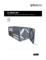
SPECIFICATIONS & DIMENSIONS
Specifications may be subject to change without notice.
Indoor UnIt
HE 1.5XInH
SpecIfIcatIonS
aIrfLow performance
Ventilation Type:
Static plate, heat and humidity transfer
Typical Airflow Range:
375–1,575 CFM
AHRI 1060 Certified Core:
One L62-G5 and one L125-G5
Standard Features:
Non-fused disconnect
24 VAC transformer/relay package
Filters:
Total Qty. 4, MERV 8: (2) 14" x 20" x 2" and
(2) 16" x 20" x 2"
Unit Dimensions & Weight:
53 1/4" L x" 34 1/2" W x 53 3/4" H
337-464 lbs.
Max. Shipping Dimensions & Weight (on pallet):
70" L x 47" W x 53" H
530 lbs.
Motor(s):
Qty. 2, 1.0 HP ea., Direct drive motorized
impeller packages
Options:
Qty. 2, ECM Motor (see ECM spec page)
- 1.0 HP 120V/1Ph/60HZ
- 1.0 HP 208-230V/1Ph/60HZ
Fused disconnect
Double wall construction
Gravity backdraft dampers
Motorized isolation dampers - OA, EA or
both airstreams
Qty. 2, Factory mounted filter alarms
Independent blower control
Accessories:
Filters - MERV 13, 2" (shipped loose)
Backdraft damper - OA or EA
Digital time clock - wall mount (TC7D-W)
Digital time clock - in exterior enclosure (TC7D-E)
Motion occupancy control - ceiling mount (MC-C)
Motion occupancy control - wall mount (MC-W)
Carbon dioxide control - wall mount (CO2-W)
Carbon dioxide control - duct mount (CO2-D)
Motor HP
Phase
External Static Pressure (Inches Water Column)
0.0 0.25 0.50 0.75 1.00 1.25 1.50
1.0
Single Phase
1,575 CFM
1,545 Watts
1,470 CFM
1,525 Watts
1,350 CFM
1,500 Watts
1,225 CFM
1,475 Watts
1,090 CFM
1,435 Watts
950 CFM
1,380 Watts
795 CFM
1,300 Watts
1.0
Three Phase
1,675 CFM
1,410 Watts
1,570 CFM
1,400 Watts
1,435 CFM
1,380 Watts
1,280 CFM
1,340 Watts
1,115 CFM
1,280 Watts
940 CFM
1,210 Watts
760 CFM
1,135 Watts
eLectrIcaL data
HP V HZ Phase
FLA
per
motor
Min.
Cir.
Amps
Max.
Overcurrent
Protection
Device
1.0 120 60 Single 6.5 14.6 20
1.0 208-230 60 Single 3.3-3.4 7.7 15
1.0 277 60 Single 2.7 6.1 15
1.0 208-230 60 Three 2.2-2.2 5.0 15
1.0 460 60 Three 1.1 2.5 15
core performance
ThermalPerformanceRatingsG52015.2.xlsx HE1.5X(IOM)
30%
50%
70%
90%
300 600 900 1,200 1,500
Effectiveness (%)
Airflow (CFM)
Note: Watts is for the entire unit (2 motors).
Note: Airflow performance includes effect of clean, standard filter supplied with unit.
At AHRI 1060 standard conditions. See all AHRI certified ratings at www.ahrinet.org.

3
1.800.627.4499 InstallatIon, operatIon and MaIntenance Manual renewaire.com
RENEWAIRE.COM 1.800.627.4499
36
SPECIFICATIONS & DIMENSIONS
Specifications may be subject to change without notice.
Indoor UnIt
HE 1.5XInH
SpecIfIcatIonS
aIrfLow performance
Ventilation Type:
Static plate, heat and humidity transfer
Typical Airflow Range:
375–1,575 CFM
AHRI 1060 Certified Core:
One L62-G5 and one L125-G5
Standard Features:
Non-fused disconnect
24 VAC transformer/relay package
Filters:
Total Qty. 4, MERV 8: (2) 14" x 20" x 2" and
(2) 16" x 20" x 2"
Unit Dimensions & Weight:
53 1/4" L x" 34 1/2" W x 53 3/4" H
337-464 lbs.
Max. Shipping Dimensions & Weight (on pallet):
70" L x 47" W x 53" H
530 lbs.
Motor(s):
Qty. 2, 1.0 HP ea., Direct drive motorized
impeller packages
Options:
Qty. 2, ECM Motor (see ECM spec page)
- 1.0 HP 120V/1Ph/60HZ
- 1.0 HP 208-230V/1Ph/60HZ
Fused disconnect
Double wall construction
Gravity backdraft dampers
Motorized isolation dampers - OA, EA or
both airstreams
Qty. 2, Factory mounted filter alarms
Independent blower control
Accessories:
Filters - MERV 13, 2" (shipped loose)
Backdraft damper - OA or EA
Digital time clock - wall mount (TC7D-W)
Digital time clock - in exterior enclosure (TC7D-E)
Motion occupancy control - ceiling mount (MC-C)
Motion occupancy control - wall mount (MC-W)
Carbon dioxide control - wall mount (CO2-W)
Carbon dioxide control - duct mount (CO2-D)
Motor HP
Phase
External Static Pressure (Inches Water Column)
0.0 0.25 0.50 0.75 1.00 1.25 1.50
1.0
Single Phase
1,575 CFM
1,545 Watts
1,470 CFM
1,525 Watts
1,350 CFM
1,500 Watts
1,225 CFM
1,475 Watts
1,090 CFM
1,435 Watts
950 CFM
1,380 Watts
795 CFM
1,300 Watts
1.0
Three Phase
1,675 CFM
1,410 Watts
1,570 CFM
1,400 Watts
1,435 CFM
1,380 Watts
1,280 CFM
1,340 Watts
1,115 CFM
1,280 Watts
940 CFM
1,210 Watts
760 CFM
1,135 Watts
eLectrIcaL data
HP V HZ Phase
FLA
per
motor
Min.
Cir.
Amps
Max.
Overcurrent
Protection
Device
1.0 120 60 Single 6.5 14.6 20
1.0 208-230 60 Single 3.3-3.4 7.7 15
1.0 277 60 Single 2.7 6.1 15
1.0 208-230 60 Three 2.2-2.2 5.0 15
1.0 460 60 Three 1.1 2.5 15
core performance
ThermalPerformanceRatingsG52015.2.xlsx HE1.5X(IOM)
30%
50%
70%
90%
300 600 900 1,200 1,500
Effectiveness (%)
Airflow (CFM)
Note: Watts is for the entire unit (2 motors).
Note: Airflow performance includes effect of clean, standard filter supplied with unit.
At AHRI 1060 standard conditions. See all AHRI certified ratings at www.ahrinet.org.
Specifications may be subject to change without notice.

renewaire.com InstallatIon, operatIon and MaIntenance Manual 1.800.627.4499
4
For the most complete and current inFormation visit renewaire.com
He-SeRieS
37
45 1/8"
Overall
1 1/8"
53 1/8"
Overall with
Damper Flanges
5 1/4"
17 3/4" Typ.
3 1/4"
FRONT VIEW
Pressure
Ports (4) Typ.
Door-interlocked
Disconnect Switch
Optional
Motorized
Damper
Optional
Motorized
Damper
FA
RA
SEE NOTE 3
EA
OA
6 1/4"
6"
6 3/8"
32"
52 3/4"
Case
LEFT VIEW
Power Wiring
Inlet 7/8" dia.
Control Wiring
Inlet 7/8" dia.
EA Duct
Flange
18" x 18"
FA Duct
Flange
18" x 18"
53 5/8"
Overall
6 3/8"
6"
32"
6 1/4"
49 3/8"
Minimum Service
Area
20 1/8"Minimum
Service Area
(Doors can be
Removed from Hinges.)
24 1/2"
RIGHT VIEW
RA Duct
Flange
18" x 18"
OA Duct
Flange
18" x 18"
Door
Swing
Door
Swing
32 5/8"
Case
34 1/2"
Overall
42 5/8" Case
5 1/4" Duct
Flange Typ.
TOP VIEW
Model: HE1.5XINH
Drawing Type: Unit Dimension
Version: APR16
ABBREVIATIONS
EA: Exhaust Air to outside
OA: Outside Air intake
RA: Room Air to be exhausted
FA: Fresh Air to inside
INSTALLATION ORIENTATION
Unit may be installed in any
orientation.
NOTE
1. UNLESS OTHERWISE SPECIFIED,
DIMENSIONS ARE ROUNDED TO THE
NEAREST EIGHTH OF AN INCH.
2. SPECIFICATIONS MAY BE SUBJECT
TO CHANGE WITHOUT NOTICE.
3. DAMPER SWING IS AWAY FROM
THE UNIT. MIN. DUCT CLEARANCE
FROM DAMPER BLADE WHEN FULLY
OPENED TO BE 2". SMACNA RULES
APPLY.
HE1.5XInH
AIrfLOw CONfIGUrATION
Available as shown in dimension drawing.
UNIT MOUNTING & APPLICATION
Can be mounted in any orientation. RA/EA airstream
can be switched with OA/FA airstream unless
certain options are selected. Duct configuration is
field convertible.

5
1.800.627.4499 InstallatIon, operatIon and MaIntenance Manual renewaire.com
For the most complete and current inFormation visit renewaire.com
He-SeRieS
41
56 1/8"
Overall with
Damper Flange
1 1/8"
17 3/4" Typ.
3 1/4"
52"
Overall without
Damper Flange
FRONT VIEW
Door-Interlocked
Disconnect Switch
Pressure
Ports (4) Typ.
Optional
Motorized
Damper
Optional
Motorized
Damper
OA
RA
FA
EA
SEE NOTE 3
46 1/4"
Overall
6 3/8"
4 1/4"
24 1/2"
6 1/4"
45 3/4"
Case
LEFT VIEW
RA Duct
Flange
18" x 18"
FA Duct
Flange
18" x 18"
6 1/4"
24 1/2"
4 1/4"
6 3/8"
RIGHT VIEW
Control Wiring
Inlet
7/8"
Power Wiring
Inlet
7/8"
EA Duct
Flange
18" x 18"
OA Duct
Flange
18" x 18"
49 5/8" Case
34 1/2"
Overall
32 5/8"
Case
5 1/4" Duct
Flange Typ.
24 1/2"
20 1/8" Minimum
Service Area
(Doors can be
Removed from
Hinges.)
49 1/2" Minimum
Service Area
TOP VIEW
Door
Swing
Door
Swing
Patch Pan
(Opening Used
for Alternative
Unit Configurations.)
Typ.
Model: HE1.5XINV
Drawing Type: Unit Dimension
Version: APR16
ABBREVIATIONS
EA: Exhaust Air to outside
OA: Outside Air intake
RA: Room Air to be exhausted
FA: Fresh Air to inside
INSTALLATION ORIENTATION
Unit may be installed in any
orientation.
NOTE
1. UNLESS OTHERWISE SPECIFIED,
DIMENSIONS ARE ROUNDED TO THE
NEAREST EIGHTH OF AN INCH.
2. SPECIFICATIONS MAY BE SUBJECT
TO CHANGE WITHOUT NOTICE.
3. DAMPER SWING IS AWAY FROM
THE UNIT. MIN. DUCT CLEARANCE
FROM DAMPER BLADE WHEN FULLY
OPENED TO BE 2". SMACNA RULES
APPLY.
HE1.5XInV
AIrfLOw CONfIGUrATION
Available as shown in dimension drawing.
UNIT MOUNTING & APPLICATION
Can be mounted in any orientation. RA/EA airstream
can be switched with OA/FA airstream unless
certain options are selected. Duct configuration is
field convertible.

ERV HE1.5XIN
WWW.RENEWAIRE.COM INSTALLATION, OPERATION AND MAINTENANCE MANUAL 1.800.627.4499
6
PLACEMENT OF THE HE1.5XIN
The HE1.5X is designed for installation indoors. Select a location that is central to the inside duct runs,
and close to both the exhaust duct (to the outside) and the fresh air duct (from the outside). The unit
can be installed in any orientation but the contractor is responsible for safe installation of the unit.
56 1/8"
Overall with
Damper Flange
1 1/8"
17 3/4" Typ.
3 1/4"
52"
Overall without
Damper Flange
FRONT VIEW
Door-Interlocked
Disconnect Switch
Pressure
Ports (4) Typ.
Optional
Motorized
Damper
Optional
Motorized
Damper
OA
RA
FA
EA
SEE NOTE 3
46 1/4"
Overall
6 3/8"
4 1/4"
24 1/2"
6 1/4"
45 3/4"
Case
LEFT VIEW
RA Duct
Flange
18" x 18"
FA Duct
Flange
18" x 18"
6 1/4"
24 1/2"
4 1/4"
6 3/8"
RIGHT VIEW
Control Wiring
Inlet
7/8"
Power Wiring
Inlet
7/8"
EA Duct
Flange
18" x 18"
OA Duct
Flange
18" x 18"
49 5/8" Case
34 1/2"
Overall
32 5/8"
Case
5 1/4" Duct
Flange Typ.
24 1/2"
20 1/8" Minimum
Service Area
(Doors can be
Removed from
Hinges.)
49 1/2" Minimum
Service Area
TOP VIEW
Door
Swing
Door
Swing
Patch Pan
(Opening Used
for Alternative
Unit Configurations.)
Typ.
Model: HE1.5XINV
Drawing Type: Unit Dimension
Version: APR16
ABBREVIATIONS
EA: Exhaust Air to outside
OA: Outside Air intake
RA: Room Air to be exhausted
FA: Fresh Air to inside
INSTALLATION ORIENTATION
Unit may be installed in any
orientation.
NOTE
1. UNLESS OTHERWISE SPECIFIED,
DIMENSIONS ARE ROUNDED TO THE
NEAREST EIGHTH OF AN INCH.
2. SPECIFICATIONS MAY BE SUBJECT
TO CHANGE WITHOUT NOTICE.
3. DAMPER SWING IS AWAY FROM
THE UNIT. MIN. DUCT CLEARANCE
FROM DAMPER BLADE WHEN FULLY
OPENED TO BE 2". SMACNA RULES
APPLY.
F1Service Area HE1.5XINH
F2Service Area HE1.5XINV
45 1/8"
Overall
1 1/8"
53 1/8"
Overall with
Damper Flanges
5 1/4"
17 3/4" Typ.
3 1/4"
FRONT VIEW
Pressure
Ports (4) Typ.
Door-interlocked
Disconnect Switch
Optional
Motorized
Damper
Optional
Motorized
Damper
FA
RA
SEE NOTE 3
EA
OA
6 1/4"
6"
6 3/8"
32"
52 3/4"
Case
LEFT VIEW
Power Wiring
Inlet 7/8" dia.
Control Wiring
Inlet 7/8" dia.
EA Duct
Flange
18" x 18"
FA Duct
Flange
18" x 18"
53 5/8"
Overall
6 3/8"
6"
32"
6 1/4"
49 3/8"
Minimum Service
Area
20 1/8"Minimum
Service Area
(Doors can be
Removed from Hinges.)
24 1/2"
RIGHT VIEW
RA Duct
Flange
18" x 18"
OA Duct
Flange
18" x 18"
Door
Swing
Door
Swing
32 5/8"
Case
34 1/2"
Overall
42 5/8" Case
5 1/4" Duct
Flange Typ.
TOP VIEW
Model: HE1.5XINH
Drawing Type: Unit Dimension
Version: APR16
ABBREVIATIONS
EA: Exhaust Air to outside
OA: Outside Air intake
RA: Room Air to be exhausted
FA: Fresh Air to inside
INSTALLATION ORIENTATION
Unit may be installed in any
orientation.
NOTE
1. UNLESS OTHERWISE SPECIFIED,
DIMENSIONS ARE ROUNDED TO THE
NEAREST EIGHTH OF AN INCH.
2. SPECIFICATIONS MAY BE SUBJECT
TO CHANGE WITHOUT NOTICE.
3. DAMPER SWING IS AWAY FROM
THE UNIT. MIN. DUCT CLEARANCE
FROM DAMPER BLADE WHEN FULLY
OPENED TO BE 2". SMACNA RULES
APPLY.
PLANNING
YOUR INSTALLATION
INSTALLATION

ERVHE1.5XIN
7
1.800.627.4499 INSTALLATION, OPERATION AND MAINTENANCE MANUAL WWW.RENEWAIRE.COM
The fresh air inlet should be at least 10’ away from
chimneys, furnace and water heater exhausts, and
other sources of carbon monoxide, humidity or other
contamination. Do not locate the fresh air inlet where
vehicles may be serviced or left idling. Never locate the
fresh air inlet inside a structure.
WARNING
NOTE: To prevent the entry of rain through the outside air inlet duct, observe the following:
1. Velocity at face of inlet hood should not exceed 500 feet per minute (fpm).
2. Inlet duct must be at least 18” x 18”.
3. Centerline length along duct from weather hood to unit inlet must be at least 48”.
4. Inlet duct must pitch downward to the outside; centerline of inlet hood must be at least 18” below
the centerline of the unit inlet.
5. Outlet duct must pitch downward to the outside with a slope of at least ¼” to the foot.
Ducts connecting the HE1.5X to the outside must be insulated, with sealed vapor barrier on both inside
and outside of the insulation. Insulate both the Outside Air (OA) and Exhaust Air (EA) ducts.
APPLICATIONS
See figure F3 for examples of some common installation approaches (HE1.5XINH shown).
F3Common Installation Approaches
PLANNING
YOUR INSTALLATION
INSTALLATION
INSIDE DUCTWORK SYSTEM
Ensure Good Ductwork Design
Ductwork should be designed to allow the unit to
provide the required airflow and reduce pressure
drop for efficient, quiet operation. If the inside
ducts run through unconditioned spaces they must
be insulated with a sealed vapor barrier on both
inside and outside of insulation.
Use Non-motorized Dampers to Set and
Balance Air
In most applications, the airflow rate for both the
Fresh Air and the Exhaust Air should be roughly
equal (or “balanced”) for best performance of the
HE1.5X Unit. See unit specification sheet for CFM/
ESP curves.
DUCTS TO THE OUTSIDE
The exhaust outlet and fresh air inlet on the
outside of the building should be at least ten feet
apart to avoid cross-contamination. The exhaust
outlet should not dump air into an enclosed space
or any other structure. The inlets and outlets
should be screened against insects and vermin
and shielded from the weather to prevent the
entry of rain or snow.

ERV HE1.5XIN
RENEwaIRE.com InstallatIon, operatIon and MaIntenance Manual 1.800.627.4499
8
PLANNING
YOUR INSTALLATION
1. Before servicing or cleaning the unit, switch power
off at disconnect switch or service panel and lock-
out/tag-out to prevent power from being switched
on accidentally. More than one disconnect switch
may be required to de-energize the equipment
for servicing.
2. This installation manual shows the suggested
installation method. Additional measures may be
required by local codes and standards.
3. Installation work and electrical wiring must be
done by qualified professional(s) in accordance
with all applicable codes, standards and licens-
ing requirements.
4. Any structural alterations necessary for instal-
lation must comply with all applicable building,
health, and safety code requirements.
5. This unit must be grounded.
6. Sufficient air is needed for proper combus-
tion and exhausting of gases through the flue
(chimney) of fuel burning equipment that might be
installed in the area affected by this equipment.
If this unit is exhausting air from a space in
which chimney-vented fuel burning equipment is
located, take steps to assure that combustion
air supply is not affected. Follow the heating
equipment manufacturer’s requirements and the
combustion air supply requirements of applica-
ble codes and standards.
7. Use the unit only in the manner intended by the
manufacturer. If you have questions, contact the
manufacturer.
8. This unit is intended for general ventilating only.
Do not use to exhaust hazardous or explosive
materials and vapors. Do not connect this unit to
range hoods, fume hoods or collection systems
for toxics.
9. When cutting or drilling into wall or ceiling, do not
damage electrical wiring and other hidden utilities.
10. If installed indoors this unit must be properly
ducted to the outdoors.
RISK OF FIRE, ELECTRIC SHOCK, OR INJURY. OBSERVE ALL CODES AND THE FOLLOWING:
WARNING
INSTALLATION
Take these simple steps to attenuate noise from the unit.
OUTSIDE THE BUILDING
Exhaust velocity noise is the primary cause of
unit-related noise outside the building. Size the
exhaust duct and grille for less than 1000 FPM
air velocity. When practical, orient the exhaust air
hood to point away from houses or public areas.
DUCTS
Make sure the ductwork at the unit outlets is
stiff enough to resist the flexure and resulting
booming associated with system start-up and
shut-off.
In general, provide smooth transitions from the
ERV’s outlets to the duct. The ducts connecting
to the outlets should be straight for a sufficient
distance, with gradual transitions to the final
duct size.
These guidelines are consistent with SMACNA
recommended duct layout practices for efficient
and quiet air movement. Follow SMACNA guidelines.
RADIATED NOISE
The HE1.5XIN is insulated with high-density
fiberglass. This provides significant attenuation
of radiated sound.
The inlet ducts can be significant sources of
radiated sound as well. The OA and RA ducts
(inlet ducts) should be insulated for sound
control. This insulation should start at the unit.
At a minimum the first ten feet of duct should be
insulated. All parts of the OA and RA ducts located
in the mechanical space should be insulated for
sound control, both to minimize sound radiation
out of these ducts and also to control sound
radiation into the ducts.
SOUND ATTENUATION
To avoid motor bearing damage
and noisy and/or unbalanced
blowers, keep drywall spray,
construction dust, etc., out of unit.
CAUTION

ERVHE1.5XIN
9
1.800.627.4499 InstallatIon, operatIon and MaIntenance Manual renewaire.com
FIELD CONVERSION
FIELD CONVERSION OF OPENINGS
The HE1.5XIN is designed to allow field conversion
of the unit openings. This means the motorized im-
peller subassemblies can be moved to an adjacent
wall of the unit if that opening is preferred. The
outlet openings can also be moved to an adjacent
wall. Before you start, plan the duct work layout.
Determine which openings are to be converted.
- Turn off the disconnect switch on the unit.
Make sure electrical power is shut off to
the unit and disconnect switch.
- Remove the access doors from the unit.
- Remove the core strap, filters, and energy
exchanger cores from the unit.
TO FIELD CONVERT INLET OPENING
1. Disconnect motor harness connector (A) by the
motor. Move the wire harness out of the way if
necessary.
2. Support the impeller subassembly. Remove the eight
¼-20 bolts (B) retaining the impeller subassembly
plate to the side rails and front and back tabs.
3. Lift the entire impeller subassembly (C) out of the
unit and set aside. Leave the rails in the unit.
4. Remove the patch pan (D) from the desired opening.
5. Using the exposed sheet metal cutout, cut the
insulation from the desired opening.
6. Seal the edges of the cut insulation to prevent
erosion of the insulation edges and having debris in
the air stream.
7. Install the patch pan over the undesired opening.
8. Install the insulation in the undesired opening. Seal
the insulation.
9. Remove the duct flange from the undesired opening
and install it at the desired opening.
10. If both inlet openings are to be converted, repeat
Steps 2 – 9 for the second inlet opening.
11. At this point, if there are outlet openings for
conversion, you will want to address them before
proceeding with the inlet opening.
12. After converting the outlet openings move the unit
floor brackets (E), if necessary, so when the unit
is re-oriented the floor brackets support the unit
on the floor.
13. Rotate the unit to the desired orientation, if necessary.
14. Install the impeller subassembly into the new inlet
opening and fasten with eight ¼-20 bolts to retain
to the side rails and front and back tabs. Make
sure the motor harness connector is towards the
front of the unit.
15. Connect the motor harness.
16. Repeat Steps 14 – 15 for other impeller
subassembly if required.
17. Tidy up any wire harnesses that were moved
making sure motor wires are taut and away from
the impeller blades.
TO FIELD CONVERT OUTLET OPENING
1. Remove the patch pan (F) from the desired opening.
2. Using the exposed sheet metal cutout, cut the
insulation from the desired opening.
3. Seal the edges of the cut insulation to prevent
erosion of the insulation edges and having debris
in the air stream.
4. Install the patch pan over the undesired opening.
5. Install the insulation in the undesired opening.
Seal the insulation.
6. Remove the duct flange (G) from the undesired
opening and install it at the desired opening.
7. If both outlet openings are to be converted, repeat
Steps 1 – 6 for the second outlet opening.
8. If Inlet Openings are being converted return to
Step 12 in the “To Field Convert Inlet Opening”
instructions.
After completion of the field conversion,
- Clean out the interior of the unit to remove any debris.
- Install energy exchanger cores, filters, and core strap.
- Install access doors on the unit
INSTALLATION

ERV HE1.5XIN
RENEwaIRE.com InstallatIon, operatIon and MaIntenance Manual 1.800.627.4499
10
INSTALLATION INSTRUCTIONS ACCESSORIES
These ERVs may be ordered with factory-installed features including Isolation Dampers and Electronically
Commutated Motors. Consult the supplemental Installation and Operation Manual(s) for these features if
supplied.
ELECTRICAL SPECIFICATIONS
Use conduit, strain reliefs, etc. as required by
code to secure the field wiring. Electrical knockouts
are provided for alternate line voltage and voltage
control locations for field wiring to the internal
electrical box. If the alternate sites are desired for
field wiring then carefully remove the knockout
plugs from the alternate sites. Insulate and plug the
open knockout locations.
NOTE: If your unit is equipped with EC Motors,
please refer to “EC Motor Manual Supplement for
RenewAire Light Commercial Units” for more detail.
MOUNTING THE UNIT
The HE1.5X is manufactured with two floor stands
for installation at floor level in an upright position.
Adequate clearance for the access door latches
must be provided.
The HE1.5X may also be hung on the wall or
suspended from a ceiling. Screw or bolt mounting
straps or brackets directly to the sheet metal case
as necessary. Remove the access doors before
installing screws — make sure your fasteners
don’t damage internal parts. Do not screw into the
access doors.
INSTALLATION
The HE1.5X weighs 340 lbs. It is the installer’s
responsibility to make sure that the screws or bolts
used for securing the units are properly selected for
the loads and substrates involved.
CAUTION
Standard HE1.5XIN with single phase original
equipment motors are NOT suitable for use with
solid state speed control.
Three phase motors are NOT suitable for use with
solid state speed control. If speed control is desired
use the VFD option.
Single phase ECM motors are NOT suitable for use
with solid state speed control. They already have
speed control built into the motor electronics.
Le HE1.5XIN avec moteurs d’équipement d’origine
monophasés ne convient pas pour une utilisation avec
regulateur de vitesse electronique.
Moteurs de trois phase ne convient pas pour utilisation
avec regulateur de vitesse electronique. Si la régulation
de vitesse est souhaité, utiliser l’option VDF.
Moteurs d’une phase de l’ECM ne conviennent pas pour
une utilisation avec regulateur de vitesse electronique.
Ils ont déjà le contrôle de vitesse intégré dans le moteur
électronique.
WARNING
Secure the HE1.5X with straps or clamps so that it
cannot fall or tip in the event of accident, structural
failure or earthquake.
WARNING

ERVHE1.5XIN
11
1.800.627.4499 InstallatIon, operatIon and MaIntenance Manual renewaire.com
TRANSFORMER
with Circuit Breaker
TRANSFORMER
with Circuit Breaker
24VAC
T1
L2 T2
L3 T3
L1
FUSES (opt.)
UNIT DISCONNECT
GND
POWER SUPPLY - 60 Hz
SEE UNIT RATING LABEL
FOR PHASE, VOLTAGE,
24VAC
1L1 2T1
3L2 4T2
5L3 6T3
C
A2 A1
CONTACTOR
MOTOR
EA
Call for Unit Operation.
24VAC
EXTERNAL NON-POWERED RELAY CONTACT
CONNECT CONTACT BETWEEN RED AND ONE YELLOW
LEAD.
CONNECT OTHER YELLOW LEAD TO BLUE.
24VAC POWER AVAILABLE AT RED AND BLUE LEAD.
KEY:
"FA" = Fresh Outside Air Blower
"EA" = Exhaust Air Blower
FACTORY WIRING HIGH-VOLTAGE
FACTORY WIRING 24VAC
FIELD WIRING HIGH-VOLTAGE
FIELD WIRING 24VAC
Unit 24VAC
Power Supply
RED
BLUE
YEL
YEL
Unit 24VAC
Power Supply
C
CONTROL CONNECTION EXAMPLES
24VAC FROM AN EXTERNAL SOURCE
CONNECT EXTERNAL 24VAC TO YELLOW LEADS.
CAP RED AND BLUE LEADS.
Call for Unit Operation.
YEL
YEL C
RED
BLUE
BLUE
RED
YEL
YEL
Damper Actuator
UNIT INTERNAL WIRING
Damper Actuator
UNIT INTERNAL WIRING
DO NOT interconnect this unit's
Class 2 Power Supply with an
External Power Supply.
MOTOR
FA
DOOR
INTERLOCK
SWITCH
14
35
C
RELAY (FA)
MOTOR THERMAL
PROTECTOR
WIRES
UNIT CONTROL WIRING SHOWN
IN CONTROL OPTIONS AT LEFT
HE1.5XIN P3 THREE PHASE UNIT - STANDARD
TRANSFORMER
with Circuit Breaker
TRANSFORMER
with Circuit Breaker
24VAC
T1
L2 T2
L3 T3
L1
FUSES (opt.)
UNIT DISCONNECT
14
35
C
RELAY
LABEL PN 165951_002
GND
POWER SUPPLY - 60 Hz
SEE UNIT RATING LABEL
FOR PHASE, VOLTAGE,
MCA AND MOPD.
L2 OMITTED WITH SINGLE-PHASE
POWER SUPPLY.
24VAC
1L1 2T1
3L2 4T2
5L3 6T3
C
A2 A1
CONTACTOR (FA)
MOTOR
FA
MOTOR
EA
UNIT CONTROL WIRING SHOWN
IN CONTROL OPTIONS AT LEFT
Call for Unit Operation.
24VAC
EXTERNAL NON-POWERED RELAY CONTACT
CONNECT CONTACT BETWEEN RED AND ONE YELLOW
LEAD.
CONNECT OTHER YELLOW LEAD TO BLUE.
24VAC POWER AVAILABLE AT RED AND BLUE LEAD.
KEY:
"FA" = Fresh Outside Air Blower
"EA" = Exhaust Air Blower
FACTORY WIRING HIGH-VOLTAGE
FACTORY WIRING 24VAC
FIELD WIRING HIGH-VOLTAGE
FIELD WIRING 24VAC
Unit 24VAC
Power Supply
RED
BLUE
YEL
YEL
Unit 24VAC
Power Supply
Relay/Actuator Coil
C
CONTROL CONNECTION EXAMPLES
UNIT INTERNAL WIRING
UNIT INTERNAL WIRING
24VAC FROM AN EXTERNAL SOURCE
CONNECT EXTERNAL 24VAC TO YELLOW LEADS.
CAP RED AND BLUE LEADS.
Call for Unit Operation.
YEL
YEL Relay/Actuator Coil
C
RED
BLUE
BLUE
RED
YEL
YEL
DO NOT interconnect this unit's
Class 2 Power Supply with an
External Power Supply.
DOOR
INTERLOCK
SWITCH
NOT AVAILABLE IN
EVERY UNIT
This wire omitted with
single-phase power
supply.
These wires omitted
with single-phase
power supply.
HE1.5XIN P1 SINGLE PHASE UNIT - STANDARD WIRING SCHEMATICS
INSTALLATION

ERV HE1.5XIN
RENEwaIRE.com InstallatIon, operatIon and MaIntenance Manual 1.800.627.4499
12
T1
L2 T2
L3 T3
L1
FUSES (opt.)
UNIT DISCONNECT
GND
POWER SUPPLY - 60 Hz
SEE UNIT RATING LABEL
FOR PHASE, VOLTAGE,
MCA AND MOPD.
KEY:
"FA" = Fresh Outside Air Blower
"EA" = Exhaust Air Blower
FACTORY WIRING HIGH-VOLTAGE
FACTORY WIRING 24VAC
FIELD WIRING HIGH-VOLTAGE
FIELD WIRING 24VAC
BLUE
RED
DO NOT interconnect this unit's
Class 2 Power Supply with an
External Power Supply.
24VAC
1L1 2T1
3L2 4T2
5L3 6T3
C
A2 A1
CONTACTOR (FA)
24VAC
1L1 2T1
3L2 4T2
5L3 6T3
C
A2 A1
CONTACTOR (EA)
MOTOR
FA
MOTOR
EA
TRANSFORMER
with Circuit Breaker
TRANSFORMER
with Circuit Breaker
24VAC
BLUE
Call for FA Blower Operation.
Call for EA Blower Operation.
Call for FA Blower Operation.
Call for EA Blower Operation.
24VAC
BLUE
RED
BLUE
YEL-FA
YEL-EA
Unit 24VAC
Power Supply
C
C
BLUE
RED
BLUE
YEL-FA
YEL-EA
Unit 24VAC
Power Supply
C
C
CONTROL CONNECTION EXAMPLES
UNIT INTERNAL WIRING
UNIT INTERNAL WIRING
TWO EXTERNAL NON-POWERED RELAY CONTACTS
SUPPLYING 24VAC FROM AN EXTERNAL SOURCE
CAP RED LEAD AND THE TAGGED BLUE LEAD.
Damper Actuator FA Blower
Damper Actuator FA Blower
TWO EXTERNAL NON-POWERED RELAY CONTACTS
CONNECT BOTH BLUE LEADS.
24VAC POWER AVAILABLE AT RED LEAD AND
TAGGED BLUE LEAD.
Damper Actuator FA Blower
Damper Actuator FA Blower
14
35
C
RELAY (FA)
14
35
C
RELAY (EA)
YEL-EA
YEL-FA
DOOR
INTERLOCK
SWITCH
MOTOR THERMAL
PROTECTOR
WIRES
MOTOR THERMAL
PROTECTOR
WIRES
UNIT CONTROL WIRING SHOWN
IN CONTROL OPTIONS AT LEFT
HE1.5XIN P3 IBC THREE PHASE UNIT WITH INDEPENDENT BLOWER CONTROL
HE1.5XIN P1 IBC SINGLE PHASE UNIT WITH INDEPENDENT BLOWER CONTROL
WIRING SCHEMATICS
INSTALLATION
TRANSFORMER
with Circuit Breaker
TRANSFORMER
with Circuit Breaker
24VAC
T1
L2 T2
L3 T3
L1
FUSES (opt.)
UNIT DISCONNECT
14
35
C
RELAY (FA)
14
35
C
RELAY (EA)
LABEL PN 165955_002
GND 24VAC
1L1 2T1
3L2 4T2
5L3 6T3
C
A2 A1
CONTACTOR (FA)
MOTOR
FA
MOTOR
EA
24VAC
1L1 2T1
3L2 4T2
5L3 6T3
C
A2 A1
CONTACTOR (EA)
POWER SUPPLY - 60 Hz
SEE UNIT RATING LABEL
FOR PHASE, VOLTAGE,
MCA AND MOPD.
L2 OMITTED WITH SINGLE-PHASE
POWER SUPPLY.
KEY:
"FA" = Fresh Outside Air Blower
"EA" = Exhaust Air Blower
FACTORY WIRING HIGH-VOLTAGE
FACTORY WIRING 24VAC
FIELD WIRING HIGH-VOLTAGE
FIELD WIRING 24VAC
Call for FA Blower Operation.
Call for EA Blower Operation.
Call for FA Blower Operation.
Call for EA Blower Operation.
24VAC
BLUE
RED
YEL-FA
YEL-EA
BLUE
BLUE
RED
BLUE
YEL-FA
YEL-EA
Unit 24VAC
Power Supply
C
C
BLUE
RED
BLUE
YEL-FA
YEL-EA
Unit 24VAC
Power Supply
Relay/Actuator Coils
(FA Blower)
(EA Blower)
C
C
CONTROL CONNECTION EXAMPLES
UNIT INTERNAL WIRING
UNIT INTERNAL WIRING
TWO EXTERNAL NON-POWERED RELAY CONTACTS
SUPPLYING 24VAC FROM AN EXTERNAL SOURCE
CAP RED LEAD AND THE TAGGED BLUE LEAD.
Relay/Actuator Coils
(FA Blower)
(EA Blower)
UNIT CONTROL WIRING SHOWN
IN CONTROL OPTIONS AT LEFT
TWO EXTERNAL NON-POWERED RELAY CONTACTS
CONNECT BOTH BLUE LEADS.
24VAC POWER AVAILABLE AT RED LEAD AND
TAGGED BLUE LEAD.
DO NOT interconnect this unit's
Class 2 Power Supply with an
External Power Supply.
NOT AVAILABLE IN
EVERY UNIT
DOOR
INTERLOCK
SWITCH
This wire omitted with
single-phase power
supply.
These wires omitted
with single-phase
power supply.

ERVHE1.5XIN
13
1.800.627.4499 InstallatIon, operatIon and MaIntenance Manual renewaire.com
LOW VOLTAGE CONTROL SYSTEM
This ERV is provided with a Class II 24VAC power
supply system that operates the unit’s contactor(s)
for HE1.5X. The ERV’s 24VAC Power Supply can
also be used to power the externally-installed con-
trols system: up to 8VA of power is available.
The unit’s power supply system includes isolation
relay(s) so you can use external controls whose
contact ratings are as low as 50mA (1.2VA). Also,
it is possible to operate the isolation relays with
24VAC power from an external source (with proper
wiring connections).
A built-in circuit-breaker prevents damage to the
transformer and other low-voltage components in
the event of a short-circuit or overload. In extreme
cases, the transformer itself is designed to fail safely.
SPECIFICATIONS
• Nominal Output Voltage under load: 24VAC
• Typical Output Voltage at no load: 29-31V
• Minimum contact rating for connected control
device: (50mA (1.2VA)
• Circuit Breaker Trip Point: 3A
1. Connect only to components intended for use with 24VAC power.
2. Do not undersize the low-voltage wires connected to this device. Observe the wire length and gauge
limits indicated in this manual.
3. Do not overload this unit’s 24VAC power supply system. Confirm that the power requirements of devices
you connect to this power supply system do not exceed 8VA in total.
4. If an external source of 24VAC power is used to control the unit, consult the wiring schematics and
connect the external power only to the specified terminals in order to avoid damaging the unit or external
controls. Connect only CLASS II power to the control terminals of this unit.
5. Unit is not equipped to receive analog signals (such as 1-10vdc or 4-20mA).
6. Unit is not equipped to communicate directly with Building Management Systems (such as BACNET,
LONWORKS, etc.). However, the unit can be controlled by powered or non-powered contacts operated by
any kind of control system.
CAUTION
HOW TO RESET THE 24VAC CIRCUIT BREAKER
If the transformer is subjected to an excessive load or a short circuit, the circuit breaker will trip to prevent
the failure of the transformer. When it trips the circuit breaker’s button pops up. Shut off the primary-side
power to the unit, and remove the excessive load or the short. The circuit breaker can be reset about
fifteen seconds after it trips by pressing in the button.
LIMITS OF POWER OUTPUT
If limits on wire gauge and length are observed, you may connect control devices that draw up to 8VA to
the blue and red wires. More than one device can be connected as long as total steady-state load does
not exceed 8VA.
OBSERVE THESE LIMITS TO WIRE LENGTH AND GAUGE
in order to ensure reliable operation of the control system.
Wire Gauge #22 #20 #18 #16 #14 #12
Circuit Length 100’ 150’ 250’ 400’ 700’ 1000’
“Circuit Length” is distance from ERV to Control Device.
INSTALLATION INSTRUCTION
If primary-side voltage is 230VAC,
move black primary-side lead from
transformer’s “208V” terminal to
the transformer’s terminal marked
“240V” (“230V” in some units).
Do not move the black primary-
side lead that is connected to the
transformer’s “COM” terminal.
CAUTION
INSTALLATION

ERV HE1.5XIN
RENEwaIRE.com InstallatIon, operatIon and MaIntenance Manual 1.800.627.4499
14
Connect Blue & First Yellow Leads
Connect Control's N.O. Output to 2nd Yellow Lead
External Control is
powered by 24VAC
available between the Red
and Blue leads.
8VA Maximum Load.
Unit 24VAC
Power Supply
C
UNIT INTERNAL CONTROL WIRING
(SIMPLIFIED)
AN EXTERNAL CONTROL DEVICE USING
UNIT'S 24VAC POWER SUPPLY
Isolation
Relay Coil
MPU
Image 2 from filename Control Connections EV450-HE1XIN_DEC14
KMC 12/11/14
BLUE
YEL
YEL
RED
NOTE: The simplified schematics below show
only the relevant portions of the low-voltage
control circuit in the ERV unit and representational
external control approaches. See the complete
unit schematics elsewhere in this manual.
CONTROL WIRING EXAMPLES BY TYPE OF APPLICATION
A. Single 2-wire Control: Use this schematic if the control requires no power to operate and acts like
a simple on/off switch. The control must not supply any power to the ERV unit. Connect the blue lead
to one yellow lead. Connect the control’s contacts to the red lead and the remaining yellow lead.
Control on separate Power Supply, no power present at Control Output:
Wire as shown for the Single 2-wire control.
C. Control operating on Unit’s 24VAC Power Supply: 24VAC power is available at the blue and red
leads. Connect one of the yellow leads to the blue lead. Connect the switched output of the Control
to the red lead to operate the ERV’s isolation relay.
B. Control Sending 24VAC “On” Signal (from an external power source) to ERV: Make sure the blue
and red leads are separately capped and not connected to any other wires. Now you safely can apply
24VAC to the two yellow leads to operate the ERV’s isolation relay.
Be careful if the external control system provides
24VAC power at its control output: make sure
blue and red leads are separately capped and not
connected to any other wires.
CAUTION
Unit 24VAC
Power Supply
Cap Blue and Red Leads when using
24VAC from external source.
C
UNIT INTERNAL CONTROL WIRING
(SIMPLIFIED)
24VAC FROM AN EXTERNAL SOURCE
Isolation
Relay Coil
Image 3 from filename Control Connections EV450-HE1XIN_DEC14
KMC 12/11/14
RED
YEL
YEL
BLUE
Unit 24VAC
Power Supply
Connect Blue & First Yellow Leads
Connect Switch between Red &
Second Yellow Leads
UNIT INTERNAL CONTROL WIRING
CIsolation
Relay Coil
(SIMPLIFIED)
A SWITCH OR NON-POWERED
CONTROL USING UNIT'S 24VAC POWER
SUPPLY
Image 1 from filename Control Connections EV450-HE1XIN_DEC14
KMC 12/11/14
BLUE
YEL
YEL
RED
AA SWITCH OR NON-POWERED CONTROL
USING UNIT’S 24VAC POWER SUPPLY
B24VAC FROM AN EXTERNAL SOURCE
CAN EXTERNAL CONTROL DEVICE USING
UNITS 24 VAC POWER SUPPLY
CONTROL WIRING
SCHEMATICS
INSTALLATION
Make sure the control provides
no voltage or current at its output
terminals.
CAUTION
Supply only 24VAC (not VDC) from
a Class II Power Source.
CAUTION
External control system should
not draw more than 8VA.
CAUTION

ERVHE1.5XIN
15
1.800.627.4499 InstallatIon, operatIon and MaIntenance Manual renewaire.com
INSTALLATION
CONTROL WIRING
SCHEMATICS
Make sure the control provides
no voltage or current at its output
terminals.
CAUTION
Supply only 24VAC (not VDC) from
a Class II Power Source.
CAUTION
D. Control System with 2 Non-powered Relay Contacts: ERVs with Independent Blower Control Only:
Use this schematic if the external control system provides no voltage or current at its output contacts.
Connect the two blue leads together. Connect the red lead to one side of each of the output contacts.
Connect the other side of the output contacts to the appropriate yellow leads (marked “FA Blower”
and “EA Blower”).
e. Control System Sending two 24VAC “On” Signals (from an external power source): ERVs with
Independent Blower Control Only: Make sure the blue and red leads are separately capped and not
connected to any other wires. Now you safely can apply one of the 24VAC signals to the one of the
yellow leads (marked “FA Blower” and “EA Blower”) and the blue lead to operate one of the ERV’s
isolation relay. Supply the second 24VAC signal to the other yellow lead and again to the blue lead
(make sure the polarity of each wire connected to the blue lead is the same).
F. Control System Operating Isolation Dampers with End Switches: Use Isolation Dampers with elec-
trically separate end switches. The end switches are used to separately control the ERV unit’s Isolation
Relays. Also, specify the ERV with Independent Blower Control. This ensures that each damper is open
before the respective blower starts up.
NOTE: Because the ERV’s contactors will only be operating once the Dampers are open, the power
draw of the Damper Actuators is allowed to be as much as 35VA while opening (including power draw
of the external control system, if any). However the power draw of the fully-opened (stalled) Actuators
(and external control system if any) must be less than 8VA.
RED
Isolation Relay Coils
(FA Blower)
(EA Blower)
BLUE
YEL
BLUE
UNIT INTERNAL WIRING
YEL
Non-Powered Relay Contacts Connected
between Red Lead and Yellow Leads
Connect 1st & 2nd Blue Leads
Unit 24VAC
Power Supply
C
C
TWO EXTERNAL NON-POWERED RELAY
CONTACTS
Image 4 from filename Control Connections EV450-HE1XIN_DEC14
KMC 12/11/14
DTWO EXTERNAL NON-POWERED
RELAY CONTACTS
RED
Isolation Relay Coils
(FA Blower)
(EA Blower)
BLUE
YEL
BLUE
UNIT INTERNAL WIRING
YEL
1st Blue Lead Capped
Unit 24VAC
Power Supply
C
C
TWO EXTERNAL RELAY CONTACTS
SUPPLYING 24VAC FROM AN
EXTERNAL SOURCE
Red Lead Capped
Image 5 from filename Control Connections EV450-HE1XIN_DEC14
KMC 12/11/14
ETWO EXTERNAL RELAY CONTACTS SUPPLYING
24VAC FROM AN EXTERNAL SOURCE

ERV HE1.5XIN
RENEwaIRE.com InstallatIon, operatIon and MaIntenance Manual 1.800.627.4499
16
EQUIPMENT REQUIRED
• A magnehelic gauge or other device capable of
measuring 0 to 1.5 in. water of differential pressure.
• 2 pieces of natural rubber latex tubing, 1/8” ID,
1/16” Wall works the best.
NOTE: Be sure to remove cap from pressure port
before inserting tubing. Insure tubing is well seated
in pressure ports.
NOTE: The tubing should extend in the pressure
port approx. 1 inch.
The individual differential static pressures (DSP)
can be measured using the installed pressure ports
located in the front of the units core access doors.
NOTE: These ports have been carefully located on
the unit as to give you the most accurate airflow
measurement. Do not relocate pressure ports.
• To read SCFM of Fresh Air (FA) install the “high”
pressure side (+) of your measuring device to the
Outside Air (OA) port and the “low” pressure side
(-) to the Fresh Air (FA) port.
• To read SCFM of Room Air (RA) install the “high”
pressure side (+) of your measuring device to the
Room Air (RA) port and the “low” pressure side
(-) to the Exhaust Air (EA) port.
• Use the reading displayed on your measurement
device to cross reference the CFM output using
the conversion chart.
NOTE: Be sure to replace cap into pressure port
when air flow measuring is completed.
CROSS CORE STATIC PRESSURE MEASUREMENT INSTRUCTIONS
MEASURING AIR FLOW
START-UP
DIFFERENTIAL STATIC ACROSS CORE DSP VS. CFM
HE1.5XIN
DSP 0.15 0.20 0.25 0.30 0.35 0.40 0.45 0.5 0.55 0.60 0.65
Fresh Air (FA) CFM 380 500 620 740 860 980 1095 1215 1330 1450 1565
Room Air (RA) CFM 320 440 565 695 825 960 1095 1235 1375 1515 -
RA
OA
EA
FA
Pressure Ports (4)
OA
FA
RA
EA
Pressure Ports (4)
RA
OA
EA
FA
Pressure Ports (4)
OA
FA
RA
EA
Pressure Ports (4)
F1AIRFLOW DIAGRAM HE1.5XINH
F1AIRFLOW DIAGRAM HE1.5XINV
NOTE: Pressure drop of clean 2” MERV-8 Filters is included in the Unit Performance Ratings Table.

ERVHE1.5XIN
17
1.800.627.4499 InstallatIon, operatIon and MaIntenance Manual renewaire.com
START-UP
FILTER SPECIFICATIONS
• (2) 14” x 20” x 2” and (2) 16” x 20” x 2” (nominal) pleated filters. Actual size: 13.5” x 19.5” x 1.75”
and 15.5” x 19.5” x 1.75”.
• Optionally (4) 15” x 20” x 2” (nominal) pleated filters can be used. Actual size: 14.5” x 19.5” x 1.75”
• Unit shipped with MERV-8 Filters. Minimum recommended effectiveness: MERV-6
MEASURING AIR FLOW
Pleated_Filter_PD_NOV15.xlsx 14+16x20x2 MERV 13 (IOM)
0.00
0.10
0.20
0.30
0.40
400 600 800 1000 1200 1400 1600
Clean-filter Pressure Drop (in.w.g.)
Unit Airflow (CFM)
Initial Pressure Drop of Optional MERV 13
Filters available for this unit
Pleated_Filter_PD_NOV15.xlsx 14+16x20x2 MERV 8 (IOM)
0.00
0.10
0.20
0.30
0.40
400 600 800 1000 1200 1400 1600
Clean-filter Pressure Drop (in.w.g.)
Unit Airflow (CFM)
Initial Pressure Drop of MERV 8 Filters
supplied with this unit
INITIAL PRESSURE DROP OF MERV 8 FILTERS SUPPLIED WITH THIS UNIT
INITIAL PRESSURE DROP OF MERV13 FILTERS AVAILABLE AS AN OPTION.
NOTE: clean filter pressure drop is included in unit airflow performance tables.
NOTE: pressure drop of standard filter is included in unit airflow performance tables.


ERVHE1.5XIN
19
1.800.627.4499 InstallatIon, operatIon and MaIntenance Manual renewaire.com
MAINTENANCE
Keep your ERV performing at its best by cleaning it as described below:
TO CLEAN THE ENERGY EXCHANGE ELEMENT
Vacuum the face of the energy exchange element yearly. Dust collects only on the entering face of the energy
exchange element, right where the filter sits. The interior of the energy exchange element stays clean even if
the element faces are dust covered.
1. Remove the filters (see below)
2. Vacuum the exposed faces of the energy exchange element with a soft brush attachment
3. Vacuum out dust from the rest of the unit case
4. Install new filters
INSPECT AND CHANGE THE FILTERS REGULARLY.
Inspect and/or replace filters every two or three months when the HE1.5X is in regular use, or as need-
ed. Filters must be used or the energy exchange core will become blocked by dust and the unit will not do its
job. In extreme cases components may be damaged.
1. To access the filters unlatch the access doors. The access doors may be removed.
2. Pull the dirty filters out and replace with new filters.
NOTE: The filters supplied in the unit are usually able to keep the energy exchange core clear for several
months. Finer filters can be used but must be cleaned more often. If using finer filters, their increased
resistance to flow must be allowed for in the system design.
MOTOR MAINTENANCE
The motor needs no lubrication. If necessary vacuum clean the blower wheels at the same time you
clean the face of the energy exchange element (annually).
WARNING
RISK OF INJURY OR DAMAGE.
Motor has an automatic reset thermal protector. Disconnect power before servicing or resetting motor thermal
protector. Use caution, motor may be hot. The motor must cool before it resets the thermal protector.
If the motor thermal protector tripped, correct the issue that caused the motor to overheat (e.g. over motor rated
amperage or locked rotor).
Danger of Electrical Shock when servicing an installed unit.
ALWAYS DISCONNECT POWER SOURCE BEFORE SERVICING! More than one disconnect switch may be required.
Proper Wiring Size Selection and Wiring Installation are the Responsibility of the Electrical Contractor.
WARNING
Don’t allow the access door to drop
when unlatched. Injury to personnel
or damage to unit may occur.
Keep fingers away from
between the access doors when
unlatching and opening the
doors. Potential PINCH POINT.
DO NOT WASH THE ENERGY
EXCHANGE CORE.
Keep it away from water or fire to
avoid damaging it. Always handle
the core carefully.
CAUTION
REQUIREMENTS
WARNING

UNMATCHED VENTILATION SUPPORT
As much as our unsurpassed quality and performance, our customers can also depend on our
professional support staff for swift, professional assistance with all their technical, application,
and service needs. Every time. Anywhere.
At RenewAire — unlike other ventilation suppliers — advanced ventilation solutions are all
we do. Our sole passion. Which is why for all commercial projects, we are the “V” in HVAC...
and the only name you need to know.
USA
(800) 627-4499
FAX: (608) 221-2824
4510 HELGESEN DRIVE
MADISON, WISCONSIN 53718 USA
WWW.RENEWAIRE.COM
CANADA
(905) 475-8989
FAX: (905) 475-5231
WWW.MITSUBISHIELECTRIC.CA
MEXICO,
CENTRAL & SOUTH AMERICA
52 (222) 2 233 911
FAX: 52 (222) 2 233 914
WWW.SOLER-PALAU.MX 138254_003 (08/16)
/