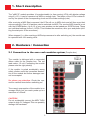
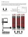
Flame µMLFO MIDI Clock lets you generate up to 14 synchronized waveforms (LFOs) with a bipolar voltage output, simultaneously. These LFOs can be synced to either MIDI or an analog clock, allowing you to effortlessly integrate them into your modular synthesizer system. With its wide range of waveforms, and adjustable rate and phase settings, the µMLFO is an ideal tool for creating dynamic and evolving soundscapes.
Flame µMLFO MIDI Clock lets you generate up to 14 synchronized waveforms (LFOs) with a bipolar voltage output, simultaneously. These LFOs can be synced to either MIDI or an analog clock, allowing you to effortlessly integrate them into your modular synthesizer system. With its wide range of waveforms, and adjustable rate and phase settings, the µMLFO is an ideal tool for creating dynamic and evolving soundscapes.


-
 1
1
-
 2
2
-
 3
3
-
 4
4
-
 5
5
-
 6
6
-
 7
7
-
 8
8
-
 9
9
-
 10
10
-
 11
11
-
 12
12
-
 13
13
-
 14
14
-
 15
15
-
 16
16


Flame µMLFO MIDI Clock lets you generate up to 14 synchronized waveforms (LFOs) with a bipolar voltage output, simultaneously. These LFOs can be synced to either MIDI or an analog clock, allowing you to effortlessly integrate them into your modular synthesizer system. With its wide range of waveforms, and adjustable rate and phase settings, the µMLFO is an ideal tool for creating dynamic and evolving soundscapes.
Ask a question and I''ll find the answer in the document
Finding information in a document is now easier with AI