
©Copyright Task Force Tips LLC 2010-2018 LIA-500 April 3, 2018 Rev07
MANUAL: LDH VALVED APPLIANCES
INSTRUCTIONS FOR INSTALLATION, SAFE OPERATION AND MAINTENANCE
WARNING Understand manual before use. Operation of this device without understanding the manual
and receiving proper training is a misuse of this equipment. Obtain safety information at
tft.com/serial-number
TASK FORCE TIPS LLC
MADE IN USA • tft.com
3701 Innovation Way, Valparaiso, IN 46383-9327 USA
800-348-2686 • 219-462-6161 • Fax 219-464-7155
OPERATING RANGE
Pressure Max 300 PSI
Pressure Min Full Vac
Hydrostatic Proof Test: 900 PSI

©Copyright Task Force Tips LLC 2010-2018 LIA-500 April 3, 2018 Rev07
2
DANGER
PERSONAL RESPONSIBILITY CODE
The member companies of FEMSA that provide emergency response
equipment and services want responders to know and understand the
following:
1. Fireghting and Emergency Response are inherently dangerous activities
requiring proper training in their hazards and the use of extreme caution
at all times.
2. It is your responsibility to read and understand any user’s instructions,
including purpose and limitations, provided with any piece of equipment
you may be called upon to use.
3. It is your responsibility to know that you have been properly trained in
Fireghting and /or Emergency Response and in the use, precautions, and
care of any equipment you may be called upon to use.
4. It is your responsibility to be in proper physical condition and to maintain
the personal skill level required to operate any equipment you may be
called upon to use.
5. It is your responsibility to know that your equipment is in operable
condition and has been maintained in accordance with the manufacturer’s
instructions.
6. Failure to follow these guidelines may result in death, burns or other
severe injury.
FEMSA
Fire and Emergency Manufacturers and Service Association
P.O. Box 147, Lynneld, MA 01940 • www.FEMSA.org

©Copyright Task Force Tips LLC 2010-2018 LIA-500 April 3, 2018 Rev07
3
Table Of Contents
1.0 MEANING OF SAFETY SIGNAL WORDS
2.0 SAFETY
3.0 GENERAL INFORMATION
3.1 PARTS IDENTIFICATION AND MODELS
3.2 SPECIFICATIONS
3.3 CORROSION
3.4 USE WITH SALT WATER:
4.0 INSTALLATION
4.1 MOUNTING THE APPLIANCE
4.2 CHANGING HANDWHEEL SIDE
4.3 CHANGING OFFSET OF CRANK HANDLE
4.4 STORZ SUCTION GASKET REQUEST
5.0 USE
5.1 VALVE OPERATION
5.2 AIR VENT AND WATER DRAIN
5.3 PRESSURE RELIEF VALVE
5.3.1 RELIEF VALVE SETTING PRESSURE
5.4 PRESSURE LOSS
5.5 SUCTION SCREEN
6.0 EXPLODED VIEWS & PARTS LISTS
6.1 MANIFOLD VALVE
6.2 IN-LINE VALVE
6.3 3-WAY MANIFOLD VALVE
6.4 4-WAY MANIFOLD VALVE
6.5 2.5” VALVE HANDLE MECHANISM
6.6 SLOW CLOSE VALVE MECHANISM
6.7 STANDARD GEARBOX
6.8 PARALLEL SHAFT GEARBOX
6.9 AIR VENT/DRAIN VALVE
610 INLET/OUTLET OPTIONS
610.1 COUPLING - MALE HOSE THREADS
6.10.2 COUPLING - FEMALE HOSE THREAD ROCKER LUG
6.10.3 COUPLING - FEMALE HOSE THREADS LONG HANDLE
6.10.4 COUPLING - STORZ
7.0 TROUBLESHOOTING
8.0 WARRANTY
9.0 MAINTENANCE
9.1 SERVICE TESTING
9.1.1 HYDRAULIC TESTING
9.1.2 RELIEF VALVE TESTING
9.1.3 SHUTOFF VALVE TESTING
9.1.4 RECORDS
9.2 CRANKSHAFT OVERRIDE AND REPLACEMENT
9.2.1 CRANKSHAFT OVERRIDE
9.2.2 DIAGNOSIS
9.2.3 CRANKSHAFT REPLACEMENT
10.0 REPAIR
11.0 ANSWERS TO YOUR QUESTIONS
12.0 INSPECTION CHECKLIST

©Copyright Task Force Tips LLC 2010-2018 LIA-500 April 3, 2018 Rev07
4
1.0 MEANING OF SAFETY SIGNAL WORDS
A safety related message is identied by a safety alert symbol and a signal word to indicate the level of risk involved with a particular
hazard. Per ANSI standard Z535.6-2011, the denitions of the four signal words are as follows:
DANGER
DANGER indicates a hazardous situation which, if not avoided, will result in death or serious
injury.
WARNING
WARNING indicates a hazardous situation which, if not avoided, could result in death or serious
injury.
CAUTION CAUTION indicates a potentially hazardous situation which, if not avoided, could result in minor
or moderate injury.
NOTICE NOTICE is used to address practices not related to physical injury.
2.0 SAFETY
WARNING
Quick changes in valve position can cause high pressure spikes due to water hammer and may
result in damaged equipment which could lead to injury or death. Open and close the valve
slowly to avoid water hammer.
WARNING
Injury or death can result from burst hoses and ttings. Be sure the pressure relief valve is set
at the proper pressure for the type of hose and equipment you are using. See NFPA 1961 and
NFPA 1962.
WARNING
Injury or death may occur by attempting to use a damaged valve.
Per NPFA 1962, the device shall be inspected and tested at least quarterly.
Before use, inspect for damage resulting from:
• Failure to drain valve followed by exposure to freezing conditions
• Exposure to temperatures in excess of 160 degrees F
• Missing parts, physical abuse
WARNING This equipment is intended for use by trained personnel for reghting. Its use for other
purposes may involve hazards not addressed by this manual. Seek appropriate guidance and
training to reduce risk of injury.
WARNING
Kinks in supply hose may reduce water ow and cause injury or death to persons dependant on
water ow. Avoid tight bends to minimize risk of hoseline kinks.
CAUTION The appliance may be damaged if frozen while containing signicant amounts of water. Such
damage may be dicult to detect visually and can lead to possible injury or death. Any time the
appliance is subject to possible damage due to freezing, it must be hydrostatically tested by
qualied personnel before being considered safe for use.
CAUTION Maximum operating pressure 300 psi (20 bar). Do not exceed 300 psi (20 bar) on either side of
the valve.
CAUTION Valve must be properly connected. Mismatched or damaged connectors may cause leaking or
uncoupling under pressure and could cause injury.
CAUTION Any alterations to the valve and its markings could diminish safety and constitutes a misuse of
this equipment.
NOTICE Use with salt water is permissible provided the LDH Valved Appliance is thoroughly cleaned with
fresh water after each use. The service life of the LDH Valved Appliance may be shortened due
to the eects of corrosion and is not covered under warranty.

©Copyright Task Force Tips LLC 2010-2018 LIA-500 April 3, 2018 Rev07
5
3.0 GENERAL INFORMATION
The products in the LDH Suite are lightweight, low friction-loss valves and manifolds that can be used in many water distribution
applications. The robust valve mechanism from the TFT Ball Intake Valve is combined with TFT’s 2.5” quarter-turn ball valves and
folding handles for the ultimate in versatility. Valve seats are eld replaceable, and quarter-turn folding valve handles require low
force to move, even under pressure. Automatic valve lock on 2.5” valves maintains valve position while owing at partial openings.
Folding handles minimize required storage space. Devices include pipe threaded port for pressure gages. All models include a
carrying handle or strap. A polymer bearing ring prevents galvanic corrosion on LDH couplings.
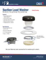
3.1 PARTS IDENTIFICATION AND MODELS
THREE-WAY VALVED MANIFOLDFOUR-WAY VALVED MANIFOLDIN-LINE VALVE
AIR VENT/
DRAIN
VALVE POSITION
INDICATOR
CRANK
PRESSURE
RELIEF VALVE
HANDWHEEL
SIDE B
CARRYING HANDLE
SIDE A
(SEAL SIDE)
VALVE POSITION
INDICATOR
IN-LINE VALVE SIDE B
FOLDING
HANDLES
SIDE A
(SEAL SIDE)
PRESSURE
RELIEF
VALVE
OPEN
CLOSED
OPENCLOSED
LDH WATER THIEF
LDH GATED WATER THIEF
SLOW CLOSE
VALVES
SIDE A
(SEAL SIDE)
SIDE B
PRESSURE
RELIEF VALVE CRANK
VALVE POSITION
INDICATOR
Figure 3.1 Parts Identication

©Copyright Task Force Tips LLC 2010-2018 LIA-500 April 3, 2018 Rev07
6
4.0 INSTALLATION
4.1 MOUNTING THE APPLIANCE
Make connections to re hose or ttings on each side of the valved appliance.
CAUTION
Dissimilar metals coupled together can cause galvanic corrosion that can result in the inability
to unscrew the threads and complete loss of thread engagement over time. Per NFPA 1962 (2013
edition), if dissimilar metals are left coupled together an anti-corrosive lubricant should be applied
to the threads. Also, the coupling should be disconnected and inspected at least quarterly.
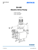
4.2 CHANGING HANDWHEEL SIDE
The handwheel can be switched to the opposite side of the gearbox
for convenience or if it interferes with other equipment.
To move the handwheel to the opposite side:
1. Remove the retaining ring on the end of the shaft.
2. Pull the shaft out of the gear box.
3. As the shaft is withdrawn, grasp the small key on the shaft so
it does not get lost.
4. Remove and switch the two plastic bushings that come out of
the sides of the gearbox. The bushing with the large hole is
installed on the same side as the handwheel.
5. Apply a small dab of grease to the key and insert it into slot
on the shaft.
5) SMALL BUSHING
1) RETAINING
RING
4) LARGE BUSHING
3) KEY
2) SHAFT ASSEMBLY
6. Look through the gear box and note approximate position of the keyway in the worm inside the gearbox. Slide the shaft into the
gearbox on the opposite side of the gearbox wit the key oriented the same as the keyway. Rotate the shaft until the key nds
the keyway and continue to slide the shaft until the hex ats protrude from the small bushing. The retaining groove should be
exposed near the hex ats.
7. Reinstall the retaining ring. Do not over expand the retaining ring.
4.3 CHANGING OFFSET OF CRANK HANDLE
REINSTALL CRANK IN THIS HOLE
IF SHORTER SWING IS DESIRED
When equipped with a crank handle, two oset positions are
available to adjust the swing radius of the crank and knob as
shown in the gure below. The longer oset position oers reduced
eort to operate the valve. The shorter oset is available to avoid
interference with other equipment. To change the oset, remove
the two 1/4-20 x 1/2” button head cap screws from crank. Place
crank in desired position and replace screws.
4.4 STORZ SUCTION GASKET REQUEST
If your application of this product requires drafting, you may need a suction gasket.
Please call 1-800-348-2686 to receive a free suction gasket by mail.
Part Numbers: 4” Storz- item #A4216, 5” Storz – item #A4221
3.2 SPECIFICATIONS
Main LDH Waterway size (at valve seat): 3.65” (93mm)
2.5” Valve waterway size: 2.5” (63.5mm)
LDH Valve meets NFPA 1965 slow close requirement.
Maximum Operating Pressure: 300 psi (20 bar)
Hydrostatic Proof Test Pressure: 900 psi (62 bar)
Temperature Rating*: -25°F to 135°F (-32°C to 57°C)
For temperatures below 32°F (0°C), valves must be drained after use to avoid damage.
See section 2.0 SAFETY.
3.3 CORROSION
Aluminum parts are hard anodized. All castings are then powder coated inside and out to help prevent corrosion. Most hose
couplings are attached using polymer bearing rings which provide electrical insulation to help prevent galvanic corrosion. The eects
of corrosion can be minimized by good maintenance practice. See section 9.0 MAINTENANCE.
3.4 USE WITH SALT WATER
Use with salt water is permissible provided valve is thoroughly cleaned with fresh water after each use. The service life of the valve
may be shortened due to the eects of corrosion and is not covered under warranty.

©Copyright Task Force Tips LLC 2010-2018 LIA-500 April 3, 2018 Rev07
7
5.0 USE
5.1 VALVE OPERATION
The valves covered by this manual utilize positive stops at the OPEN and CLOSED positions. Attempting to close a valve further than
the positive stops will not result in a tighter seal between the ball and valve seat. All valves include markings to indicate the direction
of handle rotation to open the valve.
Valves with quarter-turn handles will reach the positive stops when the handle is either parallel to the outlet (OPEN position) or
perpendicular to the outlet (CLOSED position).
Valves with hand cranks include a valve position indicator. To open the valve, turn the hand crank until the valve position indicator
shows OPEN. To close the valve, turn the hand crank the opposite way until the valve position indicator shows CLOSED.
Up to the maximum rated pressure, operating torque should never exceed the values in the table below. If greater torque is required
to operate the valve, then that is an indication that the valve needs maintenance. Exceeding 30 ft-lb / 41 N-m torque may damage
the appliance. Kicking or standing on the valve controls is considered misuse of the appliance.
Valve Seat Bore Size Max Acceptable
Torque
Max. Acceptable Force
2.5 in 63.5 mm 20 ft-lb 27 N-m 55 lb 25 kg 1/4-turn Handle
3.65 in 93 mm 12 ft-lb 16 N-m 55 lb 25 kg Knob
For valves with parallel shaft gearboxes, exceeding 30 ft-lb will result in permanent damage to several components in the gearbox.
The damage may not be outwardly obvious, but could result in inability to operate the valve. To restore normal operation, the entire
gearbox must be replaced after relieving pressure from the valve.
For valves with worm drive gearboxes, exceeding 45 ft-lb will cause one side of the crank shaft to shear o. This is intentional to
prevent further damage to the gearbox. If the shaft shears o, the valve can be operated temporarily using a wrench on the ½” hex
on the opposite side of the crankshaft. For repair instructions, see section 9.2 CRANKSHAFT OVERRIDE AND REPLACEMENT.
5.2 AIR VENT AND WATER DRAIN
CAUTION
Loss of prime can interrupt water ow and cause injury or death. Always bleed out air with air
vent/drain to prevent possible loss of prime.
This device may be equipped with an air vent/drain which will allow the air to escape from the valve when the hose is charged. The
air vent/drain is opened by turning the knob counter-clockwise and closed by turning it clockwise.
To drain the water out of the valve after use, open the air vent/drain. A ½” Diameter tube may be used to direct the drained water
away from the device.
5.3 PRESSURE RELIEF VALVE
WARNING
Do not leave the pressure relief valve in the OFF position. The pressure relief valve is disabled in
the OFF position and oers no protection against over pressurization. The OFF position may be
used for controlled pump testing but should not be used for service conditions. Exercise great
care to avoid water hammer or other pressure spikes when the pressure relief valve is in the OFF
position.
WARNING The Pressure Relief Valve may be damaged if frozen while containing signicant amounts of
water. Such damage may to dicult to detect visually and can lead to possible injury or death.
Any time the Pressure Relief Valve is subject to possible damage due to freezing, it must be
hydrostatically tested by qualied personnel before being considered safe for use.
LDH valved appliances may be equipped with a pressure relief valve that can be set to any pressure between 90 and 300 psi. Its
function is to protect the pump and supply hose from excess pressure. A piece of hose or tubing may be mounted on the round spout
to direct water coming out of the relief valve away from the device. The relief valve may be mounted with its opening facing the front,
back, right, or left. To change the orientation of the relief valve, remove the four 7/16” bolts on the corners of the relief valve ange,
orient the valve in the desired position, and replace the bolts. Use thread-locking compound on the threads of the bolts to prevent
them from vibrating loose.
See LIA-202 Pressure Relief Valve Instructions for Safe Operation and Maintenance.

©Copyright Task Force Tips LLC 2010-2018 LIA-500 April 3, 2018 Rev07
8
5.3.1 RELIEF VALVE SETTING PRESSURE
Adjusting Screw
Relief Valve
Discharge Opening
To set the relief valve pressure turn the adjusting screw on the relief
valve housing until the surface of the screw is even with the desired
pressure. A 9/16” (14mm) socket or a 1/4” Allen wrench may be used
to turn the adjusting screw. The Pressure relief valve should not be
disabled (IE: capped, plugged, or set to the OFF position) for normal
service conditions. Disabling the relief valve may result in system
damage or hose rupture if the system exceeds operating limits. The
pressure relief valve meets the requirements of NFPA 1901.
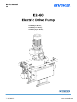
5.4 PRESSURE LOSS
0
2
4
6
8
10
12
14
16
18
20
22
24
26
0 200 400 600 800 1000 1200 1400 1600 1800 2000
FLOW (GPM)
LOSS (PSI)
0
0.5
1
1.5
2
0 1000 2000 3000 4000 5000 6000 7000
FLOW (LPM)
LOSS (BAR)
LDH Waterway
with Suction Screen
2.5"
Waterway
LDH
Waterway
Figure 5.4
Pressure Loss Chart
5.5 SUCTION SCREEN
This device may be equipped with a suction screen to catch debris larger than 3/8” diameter in the waterway. See chart in section
5.4 PRESSURE LOSS to determine additional loss caused by the screen. To add or replace a suction screen, order TFT part #
A1410-KIT.

©Copyright Task Force Tips LLC 2010-2018 LIA-500 April 3, 2018 Rev07
9
6.0 EXPLODED VIEWS & PARTS LISTS
6.1 MANIFOLD VALVE
A
B
C
D
A
B
C
D
2
1
1
F
6
5
4
8
9
10
4
K
7
K
8
9
3
11
11
1
F
ITEM DESCRIPTION QTY PART #
1 7/16-14 X 1 Hex Head Bolt 4 VT43-14HX1.0
2 Ldh Blank Cap 1 X631
3 Valve Label 1 AY305
4 O-Ring-243 2 VO-243
5 O-Ring-236 1 VO-236
6 Manifold Valve Body 1 A2005
7 1/4-20 X 5/8 Set Screw 2 VT25-20SS625
8 Valve Seat 2 AY315
9 Side B Adapter 2 1/2 Nh 2 AY360N
10 1/4-20 X 1/2 Set Screw 2 VT25-20SS500
11 Side B Adapter Hsbgm30 2 AY365
Coupling 2.5"Nh 2 P197N
3/16" Ss Ball 96 V2120
Gasket - 2.5" 2 V3190
O-Ring-151 2 VO-151
1/4-28 X 1/4 Socket Set Screw 2 VT25-28SS250
ITEM DESCRIPTION QTY PART #
A Coupling - Male Hose
Threads
- See Section
6.10.1
B Coupling - Female
Hose Threads Rocker
Lug
- See Section
6.10.2
C Coupling - Female
Hose Threads Long
Handle
- See Section
6.10.3
D Coupling - Storz - See Section
6.10.4
F Pressure Relief Valve - A1640
Vertical Pressure Relief
Valve
_ A1758
K 2.5" Valve Handle
Subassembly
- See Section
6.5
Slow Close Valve - See Section
6.7

©Copyright Task Force Tips LLC 2010-2018 LIA-500 April 3, 2018 Rev07
10
6.2 IN-LINE VALVE
33
32
33
F
27
28
29 30 31
G
26
24
23
22
25
21
20
H
J
D
C
B
A
D
C
B
A
E

©Copyright Task Force Tips LLC 2010-2018 LIA-500 April 3, 2018 Rev07
11
6.2 IN-LINE VALVE PARTS SET
ITEM DESCRIPTION QTY PART #
20 3/8-16 X 1-3/4 Socket Head Screw 4 VT37-16SH1.7
21 3/8-16 X 1-1/4 Socket Head Screw 4 VT37-16SH1.2
22 Valve Seat 1 A1520
23 1/4-20 X 1/2" Set Screw 2 VT25-20SS500
24 O-Ring-128 1 VO-128
25 Gearbox Cover 1 A1030
26 3/4"Nptm Hex Socket Plug 1 XG410
27 O-Ring-236 1 VO-236
28 Aluminum Trunnion 1 A1087A
29 In-Line Valve Body 1 A2000
30 Half Ball 1 A1043A
31 O-Ring-243 1 VO-243
32 Ldh Blank Cap 1 X631
33 7/16-14 X 1 Hex Head Bolt 4 VT43-14HX1.0
34 Bushing 1 A2094
A Coupling - Male Hose Threads - See Section 6.10.1
B Coupling - Female Hose Threads Rocker Lug - See Section 6.10.2
C Coupling - Female Hose Threads Long Handle - See Section 6.10.3
D Coupling - Storz - See Section 6.10.4
E Coupling - Male - Male - A2022
F Pressure Relief Valve - A1640
Vertical Pressure Relief Valve - A1758
G Drain Valve Subassembly - See Section 6.9
H Parallel Shaft Gearbox Subassembly - See Section 6.8
J Standard Gearbox Subassembly - See Section 6.7

©Copyright Task Force Tips LLC 2010-2018 LIA-500 April 3, 2018 Rev07
12
6.3 3-WAY VALVED MANIFOLD
55
47
46
K
48
47
55
46
54
46
53
52
51
50
49
K
48
47
55
48
K
44 45
42
43
40
F
40
41
A
C
B
D
F
1

©Copyright Task Force Tips LLC 2010-2018 LIA-500 April 3, 2018 Rev07
13
6.3 3-WAY VALVED MANIFOLD PARTS LIST
ITEM DESCRIPTION QTY PART #
40 7/16-14 X 1 Hex Head Bolt 4 VT43-14HX1.0
41 LDH Blank Cap 1 X631
42 Valve Label 1 AY305
43 O-Ring-243 1 VO-243
44 O-Ring-236 1 VO-236
45 Manifold Valve Body 1 A2005
46 1/4-20 X 5/8 Set Screw 4 VT25-20SS625
47 Valve Seat 3 AY315
48 Side B Adapter 2 1/2 Nh 3 AY360N
49 O-Ring-241 1 VO-241
50 1/4-20 X 1/2 Set Screw 2 VT25-20SS500
51 Mate Code-Rrm X 2.5" Valve 1 A2025
52 O-Ring-234 1 VO-234
53 3/4"Nptm Hex Socket Plug 1 XG410
54 2.5" Hydrant Valve Body 1 AY301
55 Side B Adapter Hsbgm30 3 AY365
Coupling 2.5"Nh 3 P197N
3/16" Ss Ball 144 V2120
Gasket - 2.5" 3 V3190
O-Ring-151 3 VO-151
1/4-28 X 1/4 Socket Set Screw 3 VT25-28SS250
A Coupling - Male Hose Threads - See Section 6.10.1
B Coupling - Female Hose Threads Rocker Lug - See Section 6.10.2
C Coupling - Female Hose Threads Long Handle - See Section 6.10.3
D Coupling - Storz - See Section 6.10.4
F Pressure Relief Valve - A1640
Vertical Pressure Relief Valve - A1758
K 2.5" Valve Handle Subassembly - See Section 6.5
Slow Close Valve - See Section 6.6

©Copyright Task Force Tips LLC 2010-2018 LIA-500 April 3, 2018 Rev07
14
6.4 4-WAY VALVED MANIFOLD
K
68
D
C
B
A
60
61
60
F
78
68
K
6564
63
62
78
67
66
K
78
67
66
76
74
73
72
71
70
69
63
78
68
67
K
68
F
1
77

©Copyright Task Force Tips LLC 2010-2018 LIA-500 April 3, 2018 Rev07
15
6.4 4-WAY VALVED MANIFOLD PARTS LIST
ITEM DESCRIPTION QTY PART #
60 7/16-14 X 1 Hex Head Bolt 4 VT43-14HX1.0
61 Ldh Blank Cap 1 X631
62 Valve Label 1 AY305
63 O-Ring-243 2 VO-243
64 O-Ring-236 1 VO-236
65 Manifold Valve Body 1 A2005
66 1/4-20 X 5/8 Set Screw 4 VT25-20SS625
67 Valve Seat 4 AY315
68 Side B Adapter 2 1/2 Nh 4 AY360N
69 Mate Code-Rrm Modifed X Psm4.25 1 A2014
70 1/4-20 X 1/2 Set Screw 2 VT25-20SS500
71 Plastic Strip 4.25" 1 A1292
72 Cup Seal Loaded 1 A1597
73 3/4"Nptm Hex Socket Plug 1 XG410
74 7/16" Stainless 302 Ball 1 VB437
76 Gated Wye Body 1 AY300
77 1/4"Npt Plug 1 VFSP2M-SS
78 Side B Adapter Hsbgm30 4 AY365
Coupling 2.5"Nh 4 P197N
3/16" Ss Ball 192 V2120
Gasket - 2.5" 4 V3190
O-Ring-151 4 VO-151
1/4-28 X 1/4 Socket Set Screw 4 VT25-28SS250
A Coupling - Male Hose Threads - See Section 6.10.1
B Coupling - Female Hose Threads Rocker Lug - See Section 6.10.2
C Coupling - Female Hose Threads Long Handle - See Section 6.10.3
D Coupling - Storz - See Section 6.10.4
F Pressure Relief Valve - A1640
Vertical Pressure Relief Valve - A1758
K 2.5" Valve Handle Subassembly - See Section 6.5
Slow Close Valve - See Section 6.6

©Copyright Task Force Tips LLC 2010-2018 LIA-500 April 3, 2018 Rev07
16
6.5 2.5” VALVE HANDLE MECHANISM
92
94
93
91
90
89
88
86
85
87
101
100
99
95
106
105
96
98
97
104
103
102
ITEM DESCRIPTION QTY PART #
85
Handle Label - Blue
1
AY342-BLU
Handle Label - Red AY342-RED
Handle Label - White AY342-WHT
86 Valve Handle 1 AY340
87 Handle Pivot Pin 1 AY345
88 1/4-20 X 3/4 Screw 2 VT25-20BH750
89 Trunnion Retainer 1 AY354
90 O-Ring-033 1 VO-033
91 Bushing 1 AY324
92 O-Ring-214 1 VO-234
93 O-Ring-011 2 VO-011
94 Outer Upper Trinnion 1 AY320
95 Floating Ring 1 AY352
96 1/4" Ss Ball 1 V2125
97 Dowel Pin 2 VP312X.50
98 Spring 1 HC115
99 Inner Upper Trunnion 1 AY350
100 O-Ring-115 2 VO-115
101 O-Ring-123 1 VO-123
102 Inner Bushing 1 AY351
103 Half Ball 1 AY310
104
Lower Trunnion
1
AY353
Lower Trunnion - XL Extension A349
Lower Trunnion - Long Extension AY355
Lower Trunnion - Short Extension AY356
105 Washer 1 G636-020
106 Belleville Spring 1 AY325

©Copyright Task Force Tips LLC 2010-2018 LIA-500 April 3, 2018 Rev07
17
6.6 2.5” SLOW CLOSE VALVE MECHANISM
13
14
8
7
6
5
4
3
2
1
9
11
13
14
10
12
11
15
16
17
18
19
ITEM DESCRIPTION QTY PART #
1 Label 1 AY370L
2 Indicator 1 AY375
3 O-Ring-113 1 VO-113
4 Knob 1 AY370
5 Ouad-Ring-214 1 VOQ-4214
6Left Sleve 1AY371L
Right Sleeve AY373R
7 1/4-20 X 3/4 Button Head Screw 2 VT25-20BH750
8Stator Left 1AY373L
Stator Right AY373R
9 O-Ring-033 1 VO-033
10 Lower Left Trunnion 1AY374L
Lower Right Trunnion AY374R
11 O-Ring-115 1 VO-115
12 Retainer 1 AY372
13 1/4-28 X 1/4 Socket Set Screw 2 VT25-28SS250
14 3/4” SS Ball (20 per upper race) 34 V2120
15 O-Ring-123 1 VO-123
16 Inner Bushing 1 AY351
17 Half Ball 1 AY310
18 Washer 1 G363-029
19 Belleville Spring 1 AY325

©Copyright Task Force Tips LLC 2010-2018 LIA-500 April 3, 2018 Rev07
18
6.7 STANDARD GEARBOX
115
116
117
118
110
109
111
112
113
114
121
122
123
124
120 119
132
131
126
125
127 128
129
130

©Copyright Task Force Tips LLC 2010-2018 LIA-500 April 3, 2018 Rev07
19
6.7 STANDARD GEARBOX PARTS LIST
ITEM DESCRIPTION QTY PART #
110 POSITION INDICATOR 1 A1517
111 SPIROL PIN 1 V1900
112 LABEL 1 A1301
113 GEARBOX 250PSI 1 A1506
114 3/8-16 X 5/16 SOCKET SET SCREW 1 VT37-16SS312
115 12 DP WORM 1 X220
116 WORM THRUST WASHER 2 A1531
117 THICK BUSHING 1 A1528
118 RETAINING RING 15MM EXTERNAL 1 VR4275
119 KEY 1 X225
120 THIN BUSHING 1 A1527
121 GEAR THRUST WASHER 1 A1502
122 INTEGRAL WORM GEAR &
TRUNNION
1 A1501
123 O-RING-214 1 VO-241
124 GEAR SPACER 1 A1511
125 3/8-16 X 1-1/2 BUTTON HEAD
SCREW
1 VT37-16BH1.5
126 CRANK BUSHING 1 A1513
127 HANDWHEEL 1 X281
128 HANDWHEEL LABEL 1 A1306
129 WASHER 1 VW812X406-65
130 KNOB 1 A1512
131 CRANK SHAFT 1 A1533
132 1/4-20 X 1/2 BUTTON HEAD SCREW 2 VT25-20BH500

©Copyright Task Force Tips LLC 2010-2018 LIA-500 April 3, 2018 Rev07
20
6.8 PARALLEL DRIVE GEARBOX
151
150
159
158
157
156
155
154
153
152
149
148
147
146
145
144
143
142
141
140
160
161
162
163
164
165
166
167
168
Page is loading ...
Page is loading ...
Page is loading ...
Page is loading ...
Page is loading ...
Page is loading ...
Page is loading ...
Page is loading ...
-
 1
1
-
 2
2
-
 3
3
-
 4
4
-
 5
5
-
 6
6
-
 7
7
-
 8
8
-
 9
9
-
 10
10
-
 11
11
-
 12
12
-
 13
13
-
 14
14
-
 15
15
-
 16
16
-
 17
17
-
 18
18
-
 19
19
-
 20
20
-
 21
21
-
 22
22
-
 23
23
-
 24
24
-
 25
25
-
 26
26
-
 27
27
-
 28
28


Task Force Tips AL92P2P3-SC Operating instructions
- Type
- Operating instructions
- This manual is also suitable for
Ask a question and I''ll find the answer in the document
Finding information in a document is now easier with AI
Related papers
-
Task Force Tips AX8NP-NX-RC1 Operating instructions
-
Task Force Tips AL72X1 Operating instructions
-
-
-
-
-
-
-
-
Other documents
-
 WaterWay Suction Load Washer User guide
-
 Binks Smart Pumps User manual
-
 Binks E4-60 User manual
-
 Binks Smart Pumps User manual
-
Carlisle Smart Pumps User manual
-
-
Brinkmann BAS6960 Operating instructions
-
MTU 8V4000M63 Operating Instructions Manual
-
 Solé Diesel MINI-17 User manual
-


