Hampton Bay 56152 Owner's manual

Category
Household fans
Type
Owner's manual

This manual is also suitable for

52” Pendleton
Ceiling Fan by Hampton Bay
3-Speed Reverse Function for
Year-Round Comfort and Savings
Oil Rubbed Bronze Finish
Remote Control
QUESTIONS, PROBLEMS, MISSING PARTS:
Before returning to your local Home Depot, please call our
Customer Service Team at 1-877-527-0313 or visit www.homedepot.com.
Please reference your SKU (672 198 oil rubbed bronze)
or UPC (82392 561529 oil rubbed bronze).
Thank you for purchasing this Hampton Bay ceiling
fan. This product has been manufactured with the
highest standards of safety and quality. The nish
of this fan is weather resistant, but over time will
naturally weather and fade.
Safety Rules .................................. 1
Unpacking Your Fan .................... 2
Installing Your Fan ...................... 3
Operating Your Fan ..................... 9
Care of Your Fan .......................... 10
Troubleshooting ............................ 10
Specications ................................ 11
Warranty Information ................. 12
Table of Contents
UL Model No. 56152
Safety Rules .................................. 1
Unpacking Your Fan .................... 2
Installing Your Fan ...................... 3
Operating Your Fan ..................... 9
Care of Your Fan .......................... 10
Troubleshooting ............................ 10
Specications ................................ 11
Warranty Information ................. 12
1. To reduce the risk of electric shock, insure electricity
has been turned off at the circuit breaker or fuse box
before beginning.
2. All wiring must be in accordance with the National
Electrical Code “ANSI/NFPA 70-1999” and local electri-
cal codes. Electrical installation should be performed by a
qualied licensed electrician.
3. WARNING: To reduce the risk of re or electric shock,
this fan should only be used with fan speed control part no.
UC7067RYK, manufactured by Rhine Electronic Co., Ltd..
4. CAUTION: To reduce the risk of personal injury, use only
the screws provided with the outlet box.
5. The outlet box and support structure must be securely
mounted and capable of reliably supporting a minimum of
35 pounds. Use only UL Listed outlet boxes marked “FOR
FAN SUPPORT.”
6. The fan must be mounted with a minimum of 7 feet
clearance from the trailing edge of the blades to the oor.
7. Do not operate reversing switch while fan blades are in mo-
tion. Fan must be turned off and blades stopped before re-
versing blade direction.
8. Avoid placing objects in path of the blades.
9. To avoid personal injury or damage to the fan and
other items, be cautious when working around or
cleaning the fan.
10. Do not use water or detergents when cleaning the fan or fan
blades. A dry dust cloth or lightly dampened cloth will be
suitable for most cleaning.
11. After making electrical connections, spliced conductors
should be turned upward and pushed carefully up into
outlet box. The wires should be spread apart with the
grounded conductor and the equipment-grounding
conductor on one side of the outlet box and ungrounded con-
ductor on the other side of the outlet box.
12. Electrical diagrams are for reference only. Light kits that are
not packed with the fan must be UL Listed and marked suit-
able for use with the model fan you are installing. Switches
must be UL General Use Switches. Refer to the instructions
packaged with the light kits and switches for proper assembly.
13. All set screws must be checked and retightened where neces-
sary before installation.
Safety Rules 1.
READ AND SAVE THESE INSTRUCTIONS
TO REDUCE THE RISK OF FIRE, ELECTRIC SHOCK OR PERSONAL IN-
JURY, MOUNT FAN TO OUTLET BOX MARKED ACCEPTABLE FOR FAN
SUPPORT WITH THE SCREWS PROVIDED WITH THE OUTLET BOX.
TO REDUCE THE RISK OF PERSONAL INJURY, DO NOT BEND THE
BLADE BRACKETS (ALSO REFERRED TO AS (“FLANGES”) DURING
ASSEMBLY OR AFTER INSTALLATION. DO NOT INSERT OBJECTS IN
THE PATH OF THE BLADES.
PLEASE REMOVE RUBBER MOTOR STOPS ON THE BOTTOM OF THE
FAN BEFORE INSTALLING BLADES OR TESTING MOTOR.
a. Blade Hardware
(45 Screws)
b. Mounting & Electrical Hardware
(1 hanger pin, 1 locking pin, 3 plastic
wire connectors)
c. Blade Balancing Kit
8. Switch Cup
9. Light Kit Assembly
10. Bulbs (2)
11. Glass
12. Finial
13. Hand Unit/Receiver
1. Mounting Plate (inside Canopy)
2. Downrod and Ball Assembly
3. Canopy
4. Decorative Motor Collar Cover
5. Fan Motor Assembly
6. Medallion (15)
7. Blades (5)
2. Unpacking Your Fan
IMPORTANT: THIS PRODUCT AND/OR COMPONENTS ARE COVERED
BY ONE OR MORE OF THE FOLLOWING U.S. PATENTS: 5,947,436;
5,988,580; 5,971,573; 6,010,306; 6,039,541; 6,046,416 AND OTHER
PATENTS PENDING.
Unpack your fan and check the contents. You should have the following items:
OK
M
Installing Your Fan 3.
Tools Required
Phillips screw driver, straight slot screw
driver, adjustable wrench, step ladder, and
wire cutters.
Mounting Options
If there isn’t an existing outlet box, then read
the following instructions. Disconnect the
power by removing fuses or turning off
circuit breakers.
Secure the outlet box directly to the building
structure. Use appropriate fasteners and
building materials. The outlet box and its
support must be able to fully support the
moving weight of the fan (at least 35 lbs.)
Do not use plastic outlet boxes.
Figures 1, 2, and 3 are examples of different
ways to mount the outlet box.
Outlet Box Note: You may need a longer downrod to
maintain proper blade clearance when install-
ing on a steep, sloped ceiling. The maximum
angle allowable is 30˚. If the canopy touches
downrod, remove the decorative canopy
bottom cover and turn the canopy 180˚ before
attaching the canopy to the mounting bracket.
To hang your fan where there is an existing
xture but no ceiling joist, you may need an
installation hanger bar as shown in Figure 4
(available at your Hampton Bay retailer).
TO REDUCE THE RISK OF FIRE, ELECTRIC
SHOCK OR PERSONAL INJURY, MOUNT
FAN ONLY TO AN OUTLET BOX MARKED
ACCEPTABLE FOR FAN SUPPORT AND
USE THE MOUNTING SCREWS PROVIDED
WITH THE OUTLET BOX. OUTLET BOXES
COMMONLY USED FOR THE SUPPORT OF
LIGHTING FIXTURES MAY NOT BE ACCEPT-
ABLE FOR FAN SUPPORT AND MAY NEED TO
BE REPLACED. CONSULT A QUALIFIED ELEC-
TRICIAN IF IN DOUBT.
Figure 1
Figure 2
Figure 4
Figure 3
4. Loosen, but do not remove, the set
screws on the collar on the top of the
motor housing.
5. Align the holes at the bottom of the
downrod with the holes in the collar
on top of the motor housing (Figure 7).
Carefully insert the hanger pin through
the holes in the collar and downrod. Be
careful not to jam the hanger pin against
the wiring inside the downrod. Insert the
locking pin through the hole near the
end of the bolt until it snaps into its
locked position, as noted in the circle inset
of Figure 7.
6. Re-tighten the set screws on the collar on top
of the motor housing.
7. Make sure the grommet is properly installed
in the collar cover, then slide the collar cover
on the downrod until it rests on the motor
housing. Be sure that the canopy and the col-
lar cover are both oriented correctly.
8. Proceed to “Installing the Fan” section.
non-slotted screws and loosen the slotted
screws. This will enable you to remove the
mounting plate (Figure 6).
3. Route the wires exiting the top of the
fan motor through the decorative motor
collar cover then the canopy ring. Make sure
the slot openings are on top. Route the wires
through the canopy and then through the
ball/downrod assembly (Figure 7).
4.
Hanging the Fan
REMEMBER to turn off the pow-
er. Follow the steps below to hang your
fan properly.
NOTE: This fan is recommended for the
standard ceiling mounting using the downrod
provided with this fan. When using standard
ceiling installation with the 6 inch downrod
provided, the distance from the ceiling to the
bottom of the fan blades will be approximately
7 inches.
IF YOU FEEL THAT YOU DO NOT HAVE
ENOUGH ELECTRICAL WIRING KNOWL-
EDGE OR EXPERIENCE, HAVE YOUR
FAN INSTALLED BY A LICENSED ELEC-
TRICIAN.
Standard Ceiling Mounting
1. Remove the canopy ring from the canopy
by turning the ring to the right until it
unlocks (Figure 5).
2. Remove the mounting plate from the
canopy by loosening the four screws on
the top of the canopy. Remove the two
THE FAN MUST BE MOUNTED WITH A MINIMUM
OF 7 FEET CLEARANCE FROM THE TRAILING
EDGE OF THE BLADES TO THE FLOOR. FAILURE TO PROPERLY INSTALL LOCKING PIN
AS NOTED IN STEP 5 COULD RESULT IN FAN
LOOSENING AND POSSIBLY FALLING.
Figure 5
Figure 6
5.
Figure 7
1. Pass the 120-volt supply wires through the
center hole in the ceiling mounting plate as
shown in Figure 7.
2. Install the ceiling mounting plate on the out-
let box by sliding the mounting plate over
the two screws provided with the outlet box
(Figure 7). If necessary, use leveling wash-
ers (not included) between the mounting
bracket and the outlet box. Note that the at
side of the mounting plate is toward the out-
let box (Figure 7).
3. Securely tighten the two mounting screws.
4. Carefully lift the fan assembly up to the ceil-
ing mounting plate. Make sure the tab on
the mounting plate is properly seated in the
groove in the hanger ball.
Making the Electrical
Connections
REMEMBER to disconnect the power. If
you feel you do not have enough electrical
wiring knowledge or experience, have your fan
installed by a licensed electrician.
Follow the steps below to connect the fan to your
household wiring (or follow the instructions
included along with the remote control).
Use the wire connecting nuts supplied with
your fan. Secure the connectors with electrical
WHEN MOUNTING THE FAN ON A SLOPED
CEILING, THE STANDARD BALL/DOWNROD
MOUNTING METHOD MUST BE USED. MAKE
SURE THE MOUNTING BRACKET SLOTS ARE
ON THE LOWER SIDE BY SLIDING THE MOUNT-
ING PLATE FROM THE TOP DOWN.
Installing Fan to
the Outlet Box
tape. Make sure there are no loose strands or
connections (Figure 8).
1. Connect both green wires from the down-
rod and mounting plate to the bare copper
(Ground) from the outlet box.
2. Connect the black wire (AC IN L) from
the receiver unit to the black wire from the
outlet box.
3. Connect the white wire (AC IN N) from
the receiver unit to the white wire from the
outlet box.
4. Connect the white wire (To Motor N) from
the receiver unit to the white wire from the
fan assembly.
5. Connect the black wire (To Motor L) from
the receiver unit to the black wire from the
fan assembly.
6. Connect the blue wire (For Light) from the
receiver unit to the blue wire from the fan.
After the wires are connected, carefully tuck
them into the outlet box. Insert the receiver unit
into the mounting plate; make sure the black an-
tenna wire sits on top of the receiver unit.
THE FREQUENCIES ON YOUR RECEIVER AND
TRANSMITTER HAVE BEEN PRESET AT THE
FACTORY. BEFORE INSTALLING THE RECEIV-
ER, MAKE SURE THE DIP SWITCHES ON THE
RECEIVER AND TRANSMITTER ARE SET TO
THE SAME FREQUENCY. THE DIP SWITCHES
ON THE TRANSMITTER ARE LOCATED INSIDE
THE BATTERY COMPARTMENT.
6.
EACH WIRE NUT (WIRE CONNECTOR) SUP-
PLIED WITH THIS FAN IS DESIGNED TO ACCEPT
UP TO ONE 12 GAUGE HOUSE WIRE AND TWO
WIRES FROM THIS FAN. IF YOU HAVE LARGER
THAN 12 GAUGE HOUSE WIRING OR MORE
THAN ONE HOUSE WIRE TO CONNECT TO THE
FAN WIRING, CONSULT AND ELECTRICIAN FOR
THE PROPER SIZE WIRE NUTS TO USE.
Figure 8
Finishing the Fan
Installation
STANDARD CEILING MOUNTING
WHEN USING THE STANDARD BALL/DOWN-
ROD MOUNTING, THE TAB IN THE RING AT THE
BOTTOM OF THE MOUNTING BRACKET MUST
REST IN THE GROOVE OF THE HANGER BALL.
FAILURE TO PROPERLY SEAT THE TAB IN THE
GROOVE COULD CAUSE DAMAGE TO WIRING.
1. Align the locking slots of the ceiling canopy
with the two screws in the mounting bracket.
Push up to engage the slots and turn clock-
wise to lock in place. Immediately tighten
the two mounting screws rmly.
2. Install the remaining two mounting
screws into the holes in the canopy and
tighten rmly.
3. Install the decorative canopy ring by align-
ing the ring’s slots with the screws in the
canopy. Rotate the ring counter-clockwise
to lock in place.
4. You may now proceed to attaching the
fan blades.
Setting the Code
This unit has 16 different code combinations.
To set the code, perform the following steps:
A. Setting the code on the transmitter:
a. Remove the battery cover. Press rmly
below arrow and slide battery cover off.
b. Slide code switches to your choice of up
or down position. (Factory setting is all up).
B. Setting the code on the receiver.
a. Slide code switches to the same position
as set on your transmitter.
b. Replace battery cover on transmitter.
CAUTION:
Ceiling angle shall not exceed 30 degrees.
Controller Model: UC7067RYK
7.
Attaching the
Fan Blades
1. Attach medallion to blade using two washer
head screws supplied (Figure 9). Start a
screw into the blade. Repeat for the remain-
ing screw.
2. Tighten each medallion securely.
3. Attach blade to blade bracket using the
screws as shown in Figure 10. Start a screw
into the bracket. Repeat for the two remain-
ing screws.
4. Repeat steps 1-3 for the remaining blades.
Figure 9
Blade Balancing
All blades are grouped by weight. Because nat-
ural woods vary in density, the fan may wobble
even though the blades are weight matched. The
following procedure should correct most fan
wobble. Check after each step.
1. Check that all blade and blade bracket
screws are secure.
2. Most fan wobble problems are caused when
blade levels are unequal. Check this level by
selecting a point on the ceiling above the tip
of one of the blades. Measure from a point
on the center of each blade to the point on the
ceiling. Measure this distance as shown in
Figure 11. Rotate the fan until the next blade
is positioned for measurement. Repeat for
each blade. Measurement deviations should
within 1/8”. Run the fan for 10 minutes.
3. Use the enclosed Blade Balancing Kit if the
blade wobble is still noticeable.
Blade
Screws
Blade Bracket
Figure 10 Figure 11
TO REDUCE RISK OF PERSONAL INJURY,
DO NOT BEND THE BLADE HOLDERS WHILE
INSTALLING, BALANCING THE BLADES OR
CLEANING THE FAN. DO NOT INSERT FOREIGN
OBJECTS BETWEEN ROTATING FAN BLADES.
8.
Installing the Light
Kit/ Glass Bowl
CAUTION - To reduce the risk of electrical
shock, disconnect the electrical supply circuit
to the fan before installing the light kit.
1. Remove one of three mounting screws on
the black bracket below the fan motor as-
sembly, loosen but do not remove the other
two mounting screws (Figure 12).
2. Align the two key slots in the switch cup
with the two mounting screws on the black
bracket that were loosened in step 1, place
the switch cup over the two screws, turn the
switch cup clockwise until it locks, tighten
the screws.
3. Re-install the mounting screw that was
removed in step 1 and tighten rmly
(Figure 12).
4. Remove one of three mounting screws on
the switch cup (Figure 13).
5. Connect the blue and white wires exiting the
switch cup below the fan motor assembly
with the black and white wires from the light
kit assembly by connecting the polarized
plugs (blue to black; white to white). Care-
fully push all wires back into the switch cup.
6. Align the two key slots in the light kit as-
sembly with the two mounting screws on
the switch cup that were loosened in step
4, place the light kit assembly over the two
screws, turn the light kit assembly clock-
wise until it locks, tighten the two screws.
7. Re-install the mounting screw that was re-
moved in step 4 and tighten rmly.
8. Remove the nial, hex nut and rubber
washer from the threaded nipple.
9. With power off, install the two uorescent
bulbs (Max 9W, supplied) by screwing into
the light bulb sockets.
10. Position the glass bowl over the threaded
nipple (Figure 13).
11. Re-install the rubber washer and hex nut to
the threaded nipple to secure the glass bowl
properly.
NOTE: ALLOW THE BULBS TO COOL
COMPLETELY BEFORE TOUCHING OR
REPLACING THE BULBS TO AVOID AC-
CIDENTAL BURNING OF THE SKIN.
12. Re-install the nial and nger tighten the
nial.
Figure 12
Figure 13
Figure 14
Operating Your Fan 9.
Figure 15
Figure 16
Transmitter Operation
Remote Control - Your fan is equipped with a
remote control to operate the speed and light for
your new ceiling fan. For more information on
how to install the remote control, see the remote
control instruction along with the remote con-
trol components.
NOTE: This remote is equipped with 16 code
combinations. To prevent possible interference
from or to other remote units such as garage
door openers, car alarm or security system, sim-
ply change the combination code but be sure
that the code on both the hand held transmitter
and receiver in the fan are matched.
Install a 9 volt battery (not included).
Operating the Fan:
Hi Key - High Speed
Med Key - Medium Speed
Low Key - Low Speed
Off Key - Power Off
Light Key - Light On/Off
Speed settings for warm or cool weather depend
on factors such as room size, ceiling height,
number of fans, and so on.
The fan shipped from the factory with the re-
versing switch positioned to circulate air down-
ward. If airow is desired in the opposite direc-
tion, turn your fan off and wait for the blades
to stop turning, then slide the reversing switch
(located at the top of the motor housing, refer
to gure 7 on page 5) to opposite position, and
turn fan on again. The fan blades will turn in the
opposite direction and reverse airow.
Warm weather - (Forward) A downward air
ow creates a cooling effect as shown in Figure
15. This allows you to set your air conditioner
on a higher setting without affecting your com-
fort.
Cool weather - (Reverse) An upward air ow
moves warm air off the ceiling are as shown in
Figure 16. This allows you to set your heating
unit on a lower setting without affecting your
comfort.
10. Care of Your Fan and Troubleshooting
Care of Your Fan
Here are some suggestions to help you
maintain your fan.
1. Because of the fan’s natural movement,
some connections may become loose.
Check the support connections, brackets,
and blade attachments twice a year. Make
sure they are secure. (It is not necessary to
remove fan from ceiling.)
2. Clean your fan periodically to help maintain
its new appearance over the years. Do not
use water when cleaning, this could damage
the motor, or the wood or possibly cause
an electrical shock. Use only a soft brush
or lint-free cloth to avoid scratching the
nish. The plating is sealed with a lacquer
to minimize discoloration or tarnishing.
Warning - Make sure the power is off
before cleaning your fan.
3. You apply a light coat of furniture polish to
the wood for additional protection and en-
hanced beauty. Cover small scratches with a
light application of shoe polish.
4. There is no need to oil your fan.
The motor has permanently lubricated
sealed ball bearings.
MAKE SURE THE POWER IS OFF AT THE ELECTRICAL PANEL BOX BE-
FORE YOU ATTEMPT TO MAKE ANY REPAIRS. REFER TO THE SECTION,
“MAKING ELECTRICAL CONNECTIONS.”
Fan will not start
Fan sounds noisy
1. Check main and branch circuit fuses or breakers
2. Check line wire connections to the fan and switch wire connections in
the switch housing. CAUTION: Make sure main power is off.
1. Make sure all motor housing screws are snug.
2. Make sure the screws that attach the fan blade bracket to the motor hub
are tight.
3. Make sure wire nut connections are not rattling against each other or
the interior wall of the switch housing. CAUTION: Make sure power
is off.
4. Allow a 24-hour “breaking in” period. Most noises associated with a
new fan disappear during this time.
5. If using the Ceiling Fan light kit, make sure the screws securing the
glassware are tight. Check that the light bulb is also secure.
6. Make sure the canopy is a short distance from the ceiling.
It should not touch the ceiling.
7. Make sure your outlet box is secure and rubber isolator pads were used
between the mounting bracket and outlet box.
Problem Solution
Specications 11.
FAN SIZE SPEED VOLTS AMPS WATTS RPM CFM NET
WEIGHT
GROSS
WEIGHT
CUBE
FEET
52”
Low 120 0.29 12 75 1980
22.5
Lbs
25.8
Lbs 2.4Med 120 0.44 32 125 3672
High 120 0.55 65 185 5573
These are approximate measures. They do not include Amps and Wattage used by the light kit.
Distributed by
Your Other Warehouse LLC
12100 Little Cayman Dr.
Baton Rouge, LA 70809
Vendor number: 219030
Hampton Bay Lifetime Limited Warranty
Lifetime Warranty on Motor
Hampton Bay warrants the fan motor to be free from defects in workmanship and material present at
time of shipment from the factory for a lifetime after the date of purchase by the original purchaser.
Hampton Bay also warrants that all other fan parts, excluding any glass or acrylic blades, to be free
from defects in workmanship and material at the time of shipment from the factory for a period of
one year after the date of purchase by the original purchaser. We agree to correct such defects without
charge or at our option replace with a comparable or superior model if the product is returned to
Hampton Bay. To obtain warranty service, you must present a copy of the receipt as proof of purchase.
All costs of removing and reinstalling the product are your responsibility. Damage to any part such
as by accident or misuse or improper installation or by afxing any accessories, is not covered by
this warranty. Because of varying climatic conditions, this warranty does not cover any changes in
plated nishes, including rusting, pitting, corroding, tarnishing or peeling. Brass nishes of this type
give their longest useful life when protected from varying weather conditions. A certain amount of
“wobble” is normal and should not be considered a defect. Servicing performed by unauthorized
persons shall render the warranty invalid. There is no other express warranty. Hampton Bay hereby
disclaims any and all warranties, including but not limited to, those of merchantability and tness
for a particular purpose to the extent permitted by law. The duration of any implied warranty which
cannot be disclaimed is limited to the time period as specied in the express warranty. Some states
do not allow limitation on how long an implied warranty lasts, so the above limitation may not apply
to you. Hampton Bay shall not be liable for incidental, consequential, or special damages arising
out of or in connection with product use or performance except as may otherwise be accorded by
law. Some states do not allow the exclusion of incidental or consequential damages, so the above
exclusion or limitation may not apply to you. This warranty gives specic legal rights, and you may
also have other rights which vary from state to state. This warranty supersedes all prior warranties.
Shipping costs for any return of product as part of a claim on the warranty must be paid by the
customer.
IMPORTANT NOTE:
To ensure warranty service, if ever
necessary, please register your fan at:
gpwarranty.com
You must present a copy of the original
purchase receipt to obtain warranty service.
G.P. WARRANTY SERVICE CENTER, INC.
WARRANTY SECTION
1951 N.W. 22nd STREET
FORT LAUDERDALE, FLORIDA 33311
Attach receipt here for
easy location.
12. Warranty Information
Pendleton de 52”
Ventilador de techo de Hampton Bay
Función de reversa de 3 velocidades para
confort y ahorro durante todo el año
Acabado bronce bruñido con aceite
Control remoto
¿PREGUNTAS, PROBLEMAS O PIEZAS FALTANTES?
Antes de volver a tu tienda local de The Home Depot, llama a nuestro
Equipo de Servicio al Cliente al 1-877-527-0313 o visita www.homedepot.com.
Por favor usa como referencia el Nº de SKU (672 198 bronce bruñido con aceite)
o UPC ( 82392 561529 bronce bruñido en aceite).
Gracias por comprar este ventilador de techo de
Hampton Bay. Este producto se ha fabricado con las
normas de seguridad y calidad más altas. El acabado
de este ventilador es resistente a la intemperie, pero
con el tiempo, exhibirá un desgaste y decoloración
naturales.
Normas de seguridad ................... 1
Cómo desempacar el ventilador .. 2
Cómo instalar el ventilador ......... 3
Cómo operar el ventilador .......... 9
Cuidado del ventilador ................ 10
Solución de problemas ................. 10
Especicaciones ............................ 11
Información de la garantía .......... 12
Índice
Modelo de UL N.º 56152
1. Para disminuir el riesgo de descarga eléctrica, asegúrate de que
la electricidad ha sido apagada en el cortacircuitos o la caja de
fusibles antes de comenzar la instalación.
2. Todo el cableado debe cumplir con el Código Nacional de
Electricidad "ANSI/NFPA 70-1999" y con los códigos locales
de electricidad. La instalación eléctrica debe ser hecha por un
electricista certicado y calicado.
3. ADVERTENCIA: Para disminuir el riesgo de incendio o
descarga eléctrica este ventilador sólo debe ser usado con un
control de velocidad con el N.o de pieza UC7067RYK, fabricado
por Rhine Electronic Co., Ltd.
4. PRECAUCIÓN: Para reducir el riesgo de lesiones físicas, usa
sólo los tornillos provistos con la caja eléctrica.
5. La caja eléctrica y estructura de soporte deben montarse de forma
segura y tener capacidad para sostener de manera conable un
mínimo de 35 libras. Usa solamente cajas eléctricas aprobadas
por UL marcadas como “PARA SOPORTE DE VENTILADOR”.
6. El ventilador debe ir montado con un mínimo de 7 pies de
separación entre el borde trasero de las aspas y el piso.
7. No operar el interruptor de reversa mientras las aspas del ventilador
estén en movimiento. El ventilador debe estar apagado y las aspas
detenidas antes de invertir la dirección del movimiento.
8. Evita colocar objetos en la trayectoria de las aspas.
9. Para evitar lesiones, o daños al ventilador y otros objetos; ten
cuidado al trabajar cerca del ventilador o al limpiarlo.
10. No usar agua o detergentes para limpiar el ventilador o las aspas.
En general a la hora de limpiar, bastará con usar un paño seco o
ligeramente humedecido.
11. Después de concluir con las conexiones eléctricas, debes voltear
los conductores empalmados hacia arriba y empujarlos con
cuidado hacia dentro de la caja eléctrica. Los cables deben estar
separados, con el cable a tierra y el conductor a tierra del equipo
hacia uno de los lados de la caja eléctrica y el conductor sin
conexión a tierra hacia el lado opuesto.
12. Los diagramas eléctricos son sólo una referencia. Los kits de
luces no empaquetados con el ventilador deben estar aprobados
por UL y marcados como apropiados para ser usados con el
modelo de ventilador a instalar. Los interruptores deberán estar
clasicados por el UL como de Uso General. Consulta las
instrucciones adjuntas a los kits de luces e interruptores para
obtener información sobre el ensamblaje adecuado.
13. Todos los tornillos colocados se deben vericar y ajustar donde
sea necesario antes de la instalación.
1. Normas de seguridad
LEE LAS INSTRUCCIONES Y GUÁRDALAS
PARA REDUCIR EL RIESGO DE LESIONES PERSONALES, NO DOBLAR
LOS BRAZOS DE LAS ASPAS (TAMBIÉN LLAMADOS “REBORDES”)
DURANTE O DESPUÉS DE LA INSTALACIÓN. EVITA COLOCAR
OBJETOS EN LA TRAYECTORIA DE LAS ASPAS.
POR FAVOR RETIRA LOS TOPES DE GOMA DEL MOTOR DE LA PARTE
INFERIOR DEL VENTILADOR ANTES DE INSTALAR LAS ASPAS O DE
PROBAR EL MOTOR.
PARA REDUCIR EL RIESGO DE INCENDIO, DESCARGA ELÉCTRICA
O LESIONES PERSONALES, MONTA EL VENTILADOR SOBRE UNA
CAJA ELÉCTRICA MARCADA COMO APROBADA COMO SOPORTE DE
VENTILADOR Y USA TORNILLOS DE MONTAJE QUE VIENEN CON LA
MISMA.
a. Herrajes de las aspas (45 tornillos)
b. Herrajes de montaje y electricidad
(1 pasador de soporte, 1 pasador de
cierre, 3 conectores plásticos de cable)
c. Kit de compensación de aspas
8. Caja del interruptor
9. Ensamblado del kit de luces
10. Bombillas (2)
11. Vidrio
12. Remate
13. Unidad de mano/receptor
1. Placa de montaje (dentro de la cubierta)
2. Ensamblado de tubo bajante y bola
3. Cubierta
4. Cubierta decorativa del collarín del motor
5. Ensamblado del motor del ventilador
6. Medallón (15)
7. Aspas (5)
Cómo desempacar el ventilador 2.
IMPORTANTE: ESTE PRODUCTO Y/O SUS COMPONENTES ESTÁN
PROTEGIDOS POR UNA O MÁS DE LAS SIGUIENTES PATENTES DE
EE.UU.: 5,947,436; 5,988,580; 5,971,573; 6,010,306; 6,039,541; 6,046,416
y OTRAS PATENTES PENDIENTES.
Desempaca tu ventilador y revisa el contenido. Deberá tener las siguientes piezas:
OK
M
3. Cómo instalar el ventilador
Herramientas necesarias
Destornillador Phillips, destornillador plano,
llave ajustable, escalera de tijera y cortacables.
Opciones de montaje
Si no hay una caja eléctrica existente, entonces
lee las siguientes instrucciones. Desconecta la
energía retirando los fusibles o apagando los
cortacircuitos.
Asegura la caja eléctrica directamente a la
estructura del edicio. Usa sujetadores y
materiales de construcción apropiados. La
caja eléctrica y su soporte deben sostener
completamente el peso en movimiento del
ventilador (al menos 35 libras). No uses cajas
eléctricas de plástico.
Las guras 1, 2 y 3 son ejemplos de diferentes
formas de montar la caja eléctrica.
Caja eléctrica
Caja eléctrica
Caja
eléctrica
empotrada
Soporte fuerte
Placa de
montaje
en el techo
Nota: Tal vez necesites un tubo bajante más
largo para mantener la altura mínima adecuada
de las aspas al instalar el ventilador en un techo
inclinado. El ángulo máximo permitido es
de 30º. Si la cubierta toca el tubo bajante,
retira la cubierta inferior decorativa y gira
la cubierta 180º antes de jar la cubierta al
soporte de montaje.
Caja eléctrica
Para colgar tu ventilador donde haya una
lámpara pero ninguna viga de techo, tal vez
necesites una barra colgante de instalación
como se muestra en la Figura 4 (disponible en
la tienda minorista local de Hampton Bay).
PARA REDUCIR EL RIESGO DE INCENDIO,
DESCARGA ELÉCTRICA O LESIONES
PERSONALES, MONTA EL VENTILADOR SÓLO
SOBRE UNA CAJA ELÉCTRICA MARCADA
COMO APROBADA COMO SOPORTE DE
VENTILADOR Y USA LOS TORNILLOS DE
MONTAJE QUE VIENEN CON LA MISMA.
LAS CAJAS ELÉCTRICAS UTILIZADAS
COMÚNMENTE PARA EL SOPORTE DE
ARTÍCULOS DE ILUMINACIÓN PUEDEN NO
SERVIR COMO SOPORTE DE VENTILADOR, Y
TAL VEZ DEBAN REEMPLAZARSE. EN CASO
DE DUDA, CONSULTA A UN ELECTRICISTA
CALIFICADO.
Figura 1
Figura 2
Figura 4
Figura 3
4. Aoja, sin quitarlos, los tornillos en el
collarín ubicado en la parte superior de la
carcasa de motor.
5. Alinea los oricios en la parte inferior del
tubo bajante con los oricios en el collarín
ubicado en la parte superior de la carcasa
de motor (Figura 7). Inserta con cuidado el
pasador de soporte a través de los oricios
del collarín y del tubo bajante. Ten cuidado
de no apretarlo contra el cableado dentro
del tubo bajante. Inserta el pasador de cierre
en el oricio cercano al extremo del perno
hasta encajarlo en su posición como se
muestra en el círculo de la Figura 7.
6. Vuelve a ajustar los tornillos del collarín en
la parte superior de la carcasa del motor
7. Asegúrate de que el ojal esté instalado
correctamente en la cubierta del collarín,
luego desliza la cubierta del collarín por el
tubo bajante hasta que quede en la carcasa
del motor. Asegúrate de que la cubierta y la
cubierta del collarín tengan la orientación
apropiada.
8. Sigue con la sección "Cómo instalar el
ventilador"
3. Inserta los cables que salen por la parte
superior del motor del ventilador, primero, a
través de la cubierta decorativa del collarín
del motor y luego, por el aro de la cubierta.
Asegúrate de que las aberturas en forma de
ranura estén en la parte superior. Inserta
los cables a través de la cubierta y luego a
través del ensamblado del tubo bajante y la
bola (Figura 7).
4.
Cómo colgar el
ventilador
RECUERDA desconectar la corriente.
Sigue estos pasos para colgar correctamente tu
ventilador.
NOTA: Se recomienda instalar este ventilador
en un techo estándar usando el tubo bajante
suministrado con el ventilador. Cuando uses
una instalación de techo estándar con el tubo
bajante de 6 pulgadas suministrado, la distancia
desde el techo a la parte inferior de las aspas
será de 7 pulgadas aproximadamente.
SI CREES QUE NO TIENES SUFICIENTE
EXPERIENCIA O CONOCIMIENTOS EN
CABLEADO ELÉCTRICO, CONTRATA A
UN ELECTRICISTA CON LICENCIA PARA
QUE INSTALE EL VENTILADOR.
Montaje de techo estándar
1. Retira el aro en la cubierta, girando a la
derecha hasta destrabarlo (Figura 5).
2. Retira la placa de montaje de la cubierta
aojando los cuatro tornillos de la parte
superior de la misma. Quita los dos tornillos
sin ranura y aoja los tornillos ranurados.
Esto te permitirá retirar la placa de montaje
(Figura 6).
ESTE VENTILADOR DEBE IR MONTADO CON
UN MÍNIMO DE 7 PIES DE SEPARACIÓN ENTRE
EL BORDE TRASERO DE LAS ASPAS Y EL PISO. SI NO INSTALAS CORRECTAMENTE EL PASA-
DOR DE CIERRE SEGÚN LO INDICADO EN EL
PASO 5 SE PUEDE AFLOJAR Y POSIBLEMENTE
SE CAIGA EL VENTILADOR.
Figura 5
Gira el aro en la cubierta para quitarla
Figura 6
Quita
r
Aflojar pero no retirar
5.
Figura 7
Apretar
los tornillos
Interruptor
de reversa
Pasador
de cierre
Posición
de cierre
del pasador
Cables del motor
Ensamblado
de tubo
bajante/bola
Cubierta
Aro de la
cubierta
Cubierta
del collarín
del motor
Pasador
de soporte
Collarín
del motor
Placa de
montaje
en el techo
Gancho
Tornillos de
montaje
(incluidos con
la caja eléctrica)
Cables de
120 voltios
Deslizar
la placa
de montaje
sobre las cabezas
de los tornillos
Caja eléctrica
aprobada
por UL
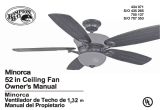
1. Pasa los cables de suministro de 120 voltios
a través del oricio central de la placa de
montaje del techo como se muestra en la
Figura 7.
2. Instala la placa de montaje del techo en la
caja eléctrica deslizando la placa de montaje
sobre los dos tornillos provistos con la caja
eléctrica (Figura 7). Si es necesario, usa
arandelas niveladoras (no incluidas) entre el
soporte de montaje y la caja eléctrica. Nota
que el lado plano de la placa de montaje está
hacia la caja eléctrica (Figura 7).
3. Ajusta rmemente los dos tornillos de
montaje.
4. Con cuidado alza el ensamblado del ventilador
hasta la placa de montaje. Asegúrate de que
la pestaña sobre la placa de montaje encaje
bien en la ranura de la bola de soporte.
Cómo hacer las
conexiones eléctricas
RECUERDA desconectar la electricidad. Si
crees que no tienes suciente experiencia o
conocimientos en cableado eléctrico, contrata
a un electricista con licencia para que instale el
ventilador.
Sigue estos pasos para conectar el ventilador a
tu circuito doméstico (o sigue las instrucciones
incluidas junto a tu control remoto). Usa las
tuercas de conexión de cables que vienen con
tu ventilador. Asegura los conectores con cinta
CUANDO MONTES EL VENTILADOR EN
UN TECHO INCLINADO, DEBES USAR EL
MÉTODO DE MONTAJE CON TUBO BAJANTE
Y BOLA ESTÁNDAR. ASEGÚRATE DE QUE LAS
RANURAS DEL SOPORTE DE MONTAJE ESTÉN
EN EL LATERAL INFERIOR MEDIANTE EL
DESLIZAMIENTO DE LA PLACA DE MONTAJE
DESDE ARRIBA HACIA ABAJO.
Cómo instalar el ventilador
en la caja eléctrica
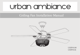
aislante. Asegúrate de que no haya cables o
conexiones sueltas (Figura 8).
1. Une los cables verdes del tubo bajante y la
placa de montaje al cable pelado de cobre
(tierra) de la caja eléctrica.
2. Conecta el cable negro (CA EN L) de la unidad
receptora al cable negro de la caja eléctrica.
3. Conecta el cable blanco (CA EN N) de la
unidad receptora al cable blanco de la caja
eléctrica.
4. Conecta el cable blanco (al Motor N) de
la unidad receptora al cable blanco del
ensamblado del ventilador.
5. Conecta el cable negro (al Motor L) de
la unidad receptora al cable negro del
ensamblado del ventilador.
6. Conecta el cable azul (Para la Luz) de la
unidad receptora al cable azul del ventilador.
Después de terminar con las conexiones,
empújalas con cuidado dentro de la caja eléctrica.
Inserta la unidad receptora dentro de la placa de
montaje; asegúrate que el cable de antena negro
quede por encima de la unidad receptora.
LAS FRECUENCIAS DEL RECEPTOR Y TRANS-
MISOR HAN SIDO PRECONFIGURADAS EN LA
FÁBRICA. ANTES DE INSTALAR EL RECEPTOR,
ASEGÚRATE DE QUE LOS INTERRUPTORES
DEL RECEPTOR Y DEL TRANSMISOR ESTÉN
CONFIGURADOS EN LA MISMA FRECUENCIA.
LOS INTERRUPTORES DEL TRANSMISOR ES-
TÁN UBICADOS DENTRO DEL COMPARTIMEN-
TO DE LA BATERÍA.
  • Page 1 1
  • Page 2 2
  • Page 3 3
  • Page 4 4
  • Page 5 5
  • Page 6 6
  • Page 7 7
  • Page 8 8
  • Page 9 9
  • Page 10 10
  • Page 11 11
  • Page 12 12
  • Page 13 13
  • Page 14 14
  • Page 15 15
  • Page 16 16
  • Page 17 17
  • Page 18 18
  • Page 19 19
  • Page 20 20
  • Page 21 21
  • Page 22 22
  • Page 23 23
  • Page 24 24
  • Page 25 25
  • Page 26 26
  • Page 27 27

Hampton Bay 56152 Owner's manual

Category
Household fans
Type
Owner's manual
This manual is also suitable for

Ask a question and I''ll find the answer in the document

Finding information in a document is now easier with AI

in other languages