10
INSTALLATION OF INDOOR, OUTDOOR UNIT
ENGLISH
Read completely, then follow step by step.
You need to select adequate installation location
considering the following conditions, and make
sure to acquire the consent of the user.
Select the best location
1 Do not have any heat or steam near the unit.
2 Select a place where there are no obstacles
in front of the unit.
3 Make sure that condensation drainage can be
conveniently routed away.
4 Do not install near a doorway.
5
Ensure the spaces indicated by arrows from the
wall, ceiling, fence or other obstacles.
6 Use a stud finder to locate studs to prevent
unnecessary damage to the wall.
1 If an awning is built over the unit to prevent
direct sunlight or rain exposure, make sure
that heat radiation from the condenser is not
restricted.
2 Ensure that the spaces indicated by arrows
around front, back and side of the unit.
3 Do not place animals and plants in the path of
the warm air.
4 Take the air conditioner weight into account
and select a place where noise and vibration
are minimum.
5 Select a place so that the warm air and noise
from the air conditioner do not disturb neigh-
bors.
6 Place that can sufficiently endure the weight
and vibration of the outdoor unit and where
even installation is possible
7 Place that has no direct influence of snow or
rain
8 Place with no danger of snowfall or icicle
drop
9 Place without weak floor or base such as
decrepit part of the building or with a lot of
snow accumulation
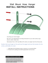
If the outdoor unit is installed on a roof structure,
be sure to level the unit. Ensure the roof struc-
ture and anchoring method are adequate for the
unit location. Consult local codes regarding
rooftop mounting.
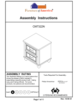
Indoor unit
Outdoor unit
Rooftop Installations
Install the indoor unit on the wall where
the height from the floors more than 2.3
meters. (ART COOL Type Only 1.5m)
CAUTION
!
More than 20cm
More than
10cm
More than 2.3m
More than
10cm
More than 20cm
More than
10cm
More than 2.3m
More than
10cm
More than 20cm
More
than 50cm
More than 1.5m
More
than 50cm
More than 20cm
More than
10cm
More than 2.3m
More than
10cm
more than
70cm
more than
30cm
more than
30cm
more than
60cm
more than 60cm
more than
70cm
more than
30cm
more than 60cm
more than
30cm
more than
60cm
INSTALLATION OF INDOOR, OUTDOOR UNIT
1,MFL67855417,영어 2017. 6. 29. 오후 2:31 페이지 10