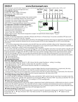
PVI TempTrac Owner's manual

Category
Gateways/controllers
Type
Owner's manual

This manual is also suitable for

PV500-49 06/12
 PVI Industries, LLC 3209 Galvez Ave. Ft. Worth, TX 76111 1-800-433-5654 Page |1
Setup Manual
BACnet Protocol Gateway for TempTrac
®
and XR
Water Heater Control
WhenaBASinterfacewithTempTracortheXRrequiresaprotocolotherthanthestandardModbus
RTU, PVI Industries offers a premapped gateway from FieldServer Technologies. The ProtoCessor
ProtoNodeRERcurrentlysupportsBACnetIPorMSTP.Consultfactoryforotherprotocols.
This manual is meant to be a general
overview of the application of this gateway, for additional
information please visit: www.protocessor.com or contact FieldServer Technologies at 8003178319
Email:[email protected]fortechnicalassistance.
The ProtoCessor ProtoNode can be user configured with the following specifics: IP address, serial
address,baudrateandoneofthreeregisterprofiles.
RS485portforHost
orFieldserial
protocolsupport
Ethernetportfor
DiagnosticsandHostor
FieldProtocolsupport
6PinRS485+/‐andFG
Power+/‐andFG5Vdc,930
VacorVdc
Dipswitches
HARDWARE DESCRIPTIO
N
Voltage
selection
jumper
PV500-49 06/12
 PVI Industries, LLC 3209 Galvez Ave. Ft. Worth, TX 76111 1-800-433-5654 Page |2
Note:WiringfortheRS485serialnetworkshouldbemadeina“daisychained”2wireshielded/twistedpair.
Protonode
+‐GNDRCGND
XR10CX
TempTrac
COMMON/SHIELD
LT
+
RS485+
/
‐
Power5Vdc,930
VacorVdc
+
XJ485SERIALINTERFACE
Optionalserialcablemustbe
o
r
de
r
ed
wi
t
h
t
h
e
h
eate
r
/
w
ate
r
PREINSTALLEDTERMINATION
OPTIONALFIELDINSTALLED
TERMINATIONRESISTOR
ModbusRTU
ProtocolIP/MSTP
S
Y
STEM OVERVIEW TEMPTRAC & X
R
XROPERATINGCONTROL
BUILDING
AUTOMATIONSYSTEM
PROTONODEGATEWAY
TEMPTRAC
OPERATINGCONTROL
PV500-49 06/12
 PVI Industries, LLC 3209 Galvez Ave. Ft. Worth, TX 76111 1-800-433-5654 Page |3
DipswitchesA0toA7configuretheserialaddress.Thetablebelowliststhesettingsupto10.Thefull
257 address settings can be found in the ProtoCessor Getting Started (T17007) manual at
www.protocessor.com.
DipswitchesS0toS3selecttheregisterprofiletobeused.
S3 S2 S1 S0 Configuration Notes
Off Off Off On Onegatewaymonitorsasingle
TempTracorXRControl
Seepage6and7forregisterlist.Allregisterswithfunctioncode(04)are
analog/16bitintegers.
Off Off On Off Onegatewaymonitorsmultiple
TempTracorXRControls
(maximum8TempTracorXR)
Seeabovetableforregisters.Registerswithfunctioncode(01)arebinary.
Waterheaternodeaddressesare1through8respectively.
Refertofullregisterlist(pages6and7)formoredetails.
A7 A6 A5 A4 A3 A2 A1 A0 Address
Off Off Off Off Off Off Off Off 0
Off Off Off Off Off Off Off On 1
Off Off Off Off Off Off On Off 2
Off Off Off Off Off Off On On 3
Off Off Off Off Off On Off Off 4
Off Off Off Off Off On Off On 5
Off Off Off Off Off On On Off 6
Off Off Off Off Off On On On 7
Off Off Off Off On Off Off Off 8
Off Off Off Off On Off Off On 9
Off Off Off Off On Off On Off 10
Baud B3 B2 B1 B0
Auto3 Off Off Off Off
110 Off Off Off On
300 Off Off On Off
600 Off Off On On
1200 Off On Off Off
2400 Off On Off On
4800 Off On On Off
9600 Off On On On
19200 On Off Off Off
20833 On Off Off On
28800 On Off On Off
38400 On Off On On
57600 On On Off Off
76800 On On Off On
115200 On On On Off
AvailableRegistersWhenSingleGatewayMonitorsMultipleControls
Control Description Modbus
Address
Alternate
Protocol
Address
TempTrac SetPoint Read/Write 40769 1
TempTrac Temp. Probe1 ReadOnly 40257 90
TempTrac Temp. Probe2 ReadOnly 40259 91
TempTrac Temp. Probe3 ReadOnly 40261 92
TempTrac On(Write257)/Off(Write255)Read/Write 41281 95
TempTrac RelayStates(bit1,2&3bitsonrelayclosed) 42050 93
TempTrac AlarmNotification(bit5onalarm) 43329 94
TempTrac HoursofOperation 40849 104
XR Temp. Probe1 ReadOnly 40257 90
XR SetPointRead/Write 40864 101
XR Temp.Probe2ReadOnly 40267 102
XR AlarmNotification(bitonalarm) 10517 103
CONFIGU
R
ATION SETTINGS TEMPTRAC & X
R
Off‐‐‐On
Dip switches B0 to B3 configure baud rate.
Thetableontherightliststhesettings.
PV500-49 06/12
 PVI Industries, LLC 3209 Galvez Ave. Ft. Worth, TX 76111 1-800-433-5654 Page |4
The default Protonode IP address may not fit within the existing network address pool. The following
instructionwilldetailthemethodforchangingtheProtonodeIP.
MakesurethattheFSTUtilitiesisdownloadedonthecomputer.
(http://fieldserver.com/techsupport/utility/utility.p hp)
Connect an ethernet crossover cable between the PC and ProtoCessor or connect the
ProtonodeandthePCtotheHub/switchusing astandardEthernetcable.
TheDefaultIPAddressoftheProtonodeis192.168.1.24,SubnetMaskis255.255.255.0.
IfthePCandtheProtododeareon
differentIPNetworks,assignaStaticIPAddresstothePCon
the192.168.1.0network.
Open the“RUIPING” Utility.If theIPAddressof theProtonode moduleappears onthe screen,
theProtonodeisrunning.
PROTONODE GATEWAY
NETWORK INTEGRATIO
N
PV500-49 06/12
 PVI Industries, LLC 3209 Galvez Ave. Ft. Worth, TX 76111 1-800-433-5654 Page |5
Startthedebuggingutility,“RUINET”(RemoteUserInterface).Thefollowingscreenwillappear:
If it is necessary to change the Protonode IP from the default address 192.168.1.24, select“I”
from the Main Menu of the Remote User Interface and enter the new address. Restart the
Protonodetoload
thenewsettings.
PROTONODE GATEWAY
NETWORK INTEGRATIO
N
PV500-49 06/12
 PVI Industries, LLC 3209 Galvez Ave. Ft. Worth, TX 76111 1-800-433-5654 Page |6
Whena gatewayispaired withonecontrol, thefullregister listis accessible.Seetheavailableregister
listbelow.Allregistersarefunctioncode04andanalog/16bitIntegers.
Control
Label
Description Range Modbus
Address
TempTrac
Alternate
Protocol
Address
St1
Set point1
LS1÷US1
40769 1
St2
Set point2
LS2÷US2
40770 2
St3
Set point3
LS3÷US3
40771 3
St5
Set point5 Set point 3 alternate
-20÷70°F
40772 4
Hy1
Differential for set1
-22÷22°F
40773 5
LS1
Minimum set point1
-40°F÷SET
40774 6
US1
Maximum set point1
SET ÷ 230°F
40775 7
AC1
Anti-short cycle delay for output 1
0÷30 min.
40776 8
S2c
Configuration of Set2: dependent on set1 or independent
diP; ind
40777 9
Hy2
Differential for set2
-22÷22°F
40778 10
LS2
Minimum set point2
-40°F÷SET2
40779 11
US2
Maximum set point2
SET2 ÷ 230°F
40780 12
AC2
Anti-short cycle delay for output 2
0÷30 min.
40781 13
S3c
Configuration of Set3: dependent on set1 or independent
diP; ind
40782 14
Hy3
Differential for set3
-22÷22°F
40783 15
LS3
Minimum set point3
-40°F÷SET3
40784 16
US3
Maximum set point3
SET3 ÷ 230°F
40785 17
AC3
Anti-short cycle delay for output 3
0÷30 min.
40786 18
o3P
Probe selection for output 3
Pb1 / Pb2
40787 19
SSE
Set point shift for output 3 enable disable
Yes / No
40788 20
Hy5
Differential for set point 5
-22÷22°F
40789 21
AC5
Anti-short cycle delay for output 3 alternate set point
0÷30 min.
40790 22
ACA
Time delay between the St3 to St5 set point shift
0÷15 min.
40791 23
S4c Configuration of Set4: dependent on set1 or independent diP; ind
40792 24
St4 Analogue output set point -100÷100°F
40793 25
SR Analogue output band width -100÷100°F
40794 26
TH4 Outlet temperature threshold for forcing to 4ma the analog output -40°F ÷ 230°F
40795 27
HY4 Differential for restart working of analog output -45 ÷ -1 °F
40796 28
Ac4 Anti-short cycle delay for output 4 0÷30 min.
40797 29
PS4 Analog output percentage LSB=101 for (nu) 0÷100, nu
40798 30
PP4 Analog output percentage with fault probe 1 0÷100, nu
40799 31
tt Outdoor temperature threshold for dynamic reset of SET1 -40÷230°F
40800 32
rr2 Outdoor temperature band width -100÷100°F
40801 33
rr1 Maximum shift of SET1 -100÷100°F
40802 34
tt2 Outdoor temperature threshold to open all the loads -40÷230°F
40803 35
Ht2 Differential for restart working of controller -45 ÷ -1 °F
40804 36
i1P Digital input 1 polarity CL÷OP
40805 37
i2P Digital input 2 polarity CL÷OP
40806 38
i2d Digital input 2 alarm delay 0÷255 min.
40807 39
i3P Digital input 3 polarity CL÷OP
40808 40
i3d Digital input 3 alarm delay 0÷255 min.
40809 41
CF Temperature measurement unit °C ÷ °F
40810 42
rES Resolution (integer/decimal point) only for °C in ÷ de
40811 43
dS2 Default showing for display #2 Pb2, Pb3
40812 44
dS1 Default showing for display #1 Pb1; tiM
40813 45
ALC
Temperature alarms configuration: dependent on SET1 or
independent
rE÷Ab
40814 46
ALL minimum temperature alarm, referred to TP1 -40÷230°F
40815 47
ALU MAXIMUM temperature alarm, referred to TP1 -40÷230°F
40816 48
FULL REGISTER LIST FOR TEMPTRA
C
PV500-49 06/12
 PVI Industries, LLC 3209 Galvez Ave. Ft. Worth, TX 76111 1-800-433-5654 Page |7
Control
Label
Description Range Modbus
Address
TempTrac
Alternate
Protocol
Address
AFH Differential for temperature alarm recovery 1÷45°F
40817 49
ALd Temperature alarm delay 0÷255 min.
40818 50
dAO Delay of temperature alarm at start up 0 ÷ 23h 50 min.
40819 51
oF1 First probe calibration -21÷21°F
40820 52
P2P Second probe presence yes; no
40821 53
oF2 Second probe calibration -21÷21°F
40822 54
P3P Third probe presence yes; no
40823 55
oF3 Third probe calibration -21÷21°F
40824 56
Hur Current hour 0 ÷ 23
40825 57
Min Current minute 0 ÷ 59
40826 58
dAY Current day Sun ÷ SAt
40827 59
E1 Energy saving start on Sunday 0 ÷ 23h 50 min. - nu
40828 60
S1 Energy saving stop on Sunday 0 ÷ 23h 50 min. - nu
40829 61
Sb1 Set back temperature on Sunday -40÷40°F
40830 62
E2 Energy saving start on Monday 0 ÷ 23h 50 min. - nu
40831 63
S2 Energy saving stop on Monday 0 ÷ 23h 50 min. - nu
40832 64
Sb2 Set back temperature on Monday -40÷40°F
40833 65
E3 Energy saving start on Tuesday 0 ÷ 23h 50 min. - nu
40834 66
S3 Energy saving stop on Tuesday 0 ÷ 23h 50 min. - nu
40835 67
Sb3 Set back temperature on Tuesday -40÷40°F
40836 68
E4 Energy saving start on Wednesday 0 ÷ 23h 50 min. - nu
40837 69
S4 Energy saving stop on Wednesday 0 ÷ 23h 50 min. - nu
40838 70
Sb4 Set back temperature on Wednesday -40÷40°F
40839 71
E5 Energy saving start on Thursday 0 ÷ 23h 50 min. - nu
40840 72
S5 Energy saving stop on Thursday 0 ÷ 23h 50 min. - nu
40841 73
Sb5 Set back temperature on Thursday -40÷40°F
40842 74
E6 Energy saving start on Friday 0 ÷ 23h 50 min. - nu
40843 75
S6 Energy saving stop on Friday 0 ÷ 23h 50 min. - nu
40844 76
Sb6 Set back temperature on Friday -40÷40°F
40845 77
E7 Energy saving start on Saturday 0 ÷ 23h 50 min. - nu
40846 78
S7 Energy saving stop on Saturday 0 ÷ 23h 50 min. - nu
40847 79
Sb7 Set back temperature on Saturday -40÷40°F
40848 80
oP1 working hours limit of relay 1 (set to 0 to disable) 0÷9999h
40849 81
oP2 working hours limit of relay 2 (set to 0 to disable) 0÷9999h
40850 82
oP3 working hours limit of relay 3 (set to 0 to disable) 0÷9999h
40851 83
ou1 working hours actual of relay 1 0÷9999h; when enabled
40852 84
ou2 working hours actual of relay 2 0÷9999h; when enabled
40853 85
ou3 working hours actual of relay 3 0÷9999h; when enabled
40854 86
1on The output 1 is always on or depending on temperature rEG=1,1;YES=0,1; no=0,0
40855 87
2on The output 2 is always on or depending on temperature rEG=1,1;YES=0,1; no=0,0
40856 88
3on The output 3 is always on or depending on temperature rEG=1,1;YES=0,1; no=0,0
40857 89
Probe 1 temperature (return water or tank control sensor)
DegreesF/C(readonly) 40257 90
Probe 2 temperature (supply water or tank outlet)
DegreesF/C(readonly)
40259 91
Probe 3 temperature (outdoor temp or system temp with
OnTrac)
DegreesF/C(readonly)
40261 92
States of Relays 1,2&3
Bit0,1and2(readonly) 42050 93
Digital input alarms
Bit5(readonly) 43329 94
On/Off ( bit 0 of MS 1on 0off, LS 1enable 0 disable)
41281 95
Keyboard Lock (bit 4 of MS 1lock 0un, LS 1enable 0 disable)
41281 95
Reset audible alarm (bit 5 of MS 1reset. LS 1enable 0 disable)
41281 95
Adr Serial address
1to248 40858 96
rEL Software release
(readonly) 40859 97
Ptb Parameter map code
(readonly) 40860 98
PV500-49 06/12
 PVI Industries, LLC 3209 Galvez Ave. Ft. Worth, TX 76111 1-800-433-5654 Page |8
Inorder to set upthe networkcommunication
system,each water heater’s TempTraccontrol mustbe
assigned an address.In installations with multiple TempTrac controls, a different address must be
assignedtoeachTempTrac.
Thefollowinginstructionsarespecificto the TempTrac
®.Ifyourwaterheaterusesadifferentcontrol
refertotheprogrammingi nstructionfor thatcon troltosettheaddress.
1. On the face of the TempTrac control, enter the programming mode by pressing
andholdingtheset”anddownarrow”keystogetherfor3seconds.
2. The upper LED readout should read “St1” with a numeral (the St1 setting) appearing in the lower
LEDreadout.
IMPORTANT: If the lower readout indicates “Pof”, the TempTrac control is locked for programming. To
unlockthe control,press and hold the uparrow anddownarrow keys togetheruntilthe lower
LEDreadoutindicates“Pon”.TheTempTraccontrolisnowunlocked.Repeatstep1toproceedwith
assigningtheTempTracaddress.
3. Pressthe“downarrow”key.
4. “Pr2” will appear in the upper LED readout and “Pas” will appear in the lower LED readout.
Pressthesetkeytobeginenteringthepasswordtoallowprogramming.
5. InthelowerLED,thevalue“0‐‐(zero,dash,dash)
withaflashingzerowillbedisplayed.
6. The programming password is “321”. Use up arrow key to input each digit in the security code.
Confirmeachdigitbypressingsetkey.Aftereachconfirmation,thenextdigitwillbegintoflash.
7. After entering the third digit and
pressing set”, “Pr2” will appear in the
upper LED readout. Press the down arrow” key three times and the
parameter “Adr” will appear in the upper LED readout. The lower LED
readoutwillindicatethedefaultaddress“1”.(Seeimagetotheright.)
8. Press the set” key
once and the number will begin to blink. Use the up
arrow” key to set the address from (1 to 20). When the proper address is
indicatedinthelowerLED,presssetkey.
9. The address is programmed. After approximately 10 minutes, the LED
readoutswillreturn
tothedefaulttemperaturereadingmode.
ASSIGNING
W
ATER HEATE
R
ADDRESSE
S
Adr
1
PV500-49 06/12
 PVI Industries, LLC 3209 Galvez Ave. Ft. Worth, TX 76111 1-800-433-5654 Page |9
PowerLEDcomesonandremainssolid.
LAstartsflashingabout oncepersecond. This tellsusthat PIC(PeripheralInterface Controller)
number1intheProtoCessorhaspoweredupsuccessfully.
LBstartsflashingaboutoncepersecond.ThistellsusthatPICnumber2intheProtoCessor
has
poweredupsuccessfully.
GP105 will go on solid within 45 60 seconds after power up, signifying normal operation.
ProtoCessorwillbeabletocomeupinRUINETshortlyafterthisLEDcomeson.Duringthefirst
4560secondstheLEDshouldbedark.
Uponsuccessful
operationofGP105theProtoCessorwillgothroughdiagnosticsofthefieldport
communications.
TheFFPETHmoduleisoperationalafterthispoint.
RXFieldPortLED:Onnormaloperation, theRXLEDwillflashwhenamessageisreceivedonthe
fieldportoftheProtoCessor.
TXFieldPortLED:Onnormaloperation,theTXLEDwillflashwhenamessageissentonthefield
portoftheProtoCessor.
POWERING UP THE PROT
O
CESSOR/PROTONOD
E
PWR
GP105
LB
TX
RX
LA
PV500-49 06/12
 PVI Industries, LLC 3209 Galvez Ave. Ft. Worth, TX 76111 1-800-433-5654 Page |10
Oncethenetwork isconfiguredtheConnectionOverviewoftheRUINETutilitywill showthemessages
astheymoveacrossthenetwork.
Select “O” for Connect Overview to see the number of messages on each protocol. If the
Protonode is communicating correctly with the device then the display will
show Tx and Rx
messageswithoutanyerrors.
If PWR LED does not come on and LA and LB don’t flash, call or email ProtoCessor support
IfPWRLEDdoesnotcomeonbuttheLAandLBflash,thenthePWRLEDisbroken.
IfLAandLBdon’tstarttoflashtherecould
beaproblemwiththeProtoCessorandyouneedto
contact[email protected].
IfGP105nevercomesonthenyouneedtocontactProtoCessorsupport.
If TX and or RX don’t flash, it may represent a problem with the field wiring or Configuration
problems in the ProtoCessor on
field side or incorrect polling parameters (such as COMM
propertieslikebaud,parity,andetc).
TheProtonodeisunabletofindoneormorecontrolsintheRS485network.
o The i ndividual controls may not be programmed with the correct and unique nod e
address.Seetherespectivecontrolmanual
fordetails.
TheProtonodehasnocommunicationwiththecontrolsintheRS485network.
o Check the RS485 wiring for correct wiring method. See page 12 of this manual for
details.
It is a good idea to Ping both Protonode gateway to be certain the intended address are accessible
before
engaginginadditionaltroubleshooting.
MoreinformationfortheProtoCessor/ProtoNodecanbefoundat:Web:www.protocessor.com
FieldServerTechnologies,1991TarobCourt,Milpitas,California95035USA
Tel:4089644433,FAX:4082629042,TollFree:8003178319Email:[email protected]
TROUBLESHOOTING TIP
S
PROTONODE GATEWAY
NETWORK INTEGRATIO
N
  • Page 1 1
  • Page 2 2
  • Page 3 3
  • Page 4 4
  • Page 5 5
  • Page 6 6
  • Page 7 7
  • Page 8 8
  • Page 9 9
  • Page 10 10

PVI TempTrac Owner's manual

Category
Gateways/controllers
Type
Owner's manual
This manual is also suitable for

Ask a question and I''ll find the answer in the document

Finding information in a document is now easier with AI