© 2018 OJ Electronics A/S
9
© 2018 OJ Electronics A/S
Cautions
This instruction must be observed, otherwise the liability
of the manufacturer shall be voided.
Any changes or modifications made to this thermostat
shall void the liability of the manufacturer.
Maximum product lifetime is achieved if the product is not turned
o but set at the lowest possible set point / frost protection when
heat is not required.
Notice
The language used in the original documentation is
English.
Other language versions are a translation of the original
documentation.
The manufacturer cannot be held liable for any errors in the
documentation. The manufacturer reserves the right to make
alterations without prior notice.
Content may vary due to alternative software and/or
configurations.
Fig. 3 - Thermostat placement
Mounting of sensor
The floor sensor contains a safety extra-low voltage (SELV) circuit,
allowing it to be placed as close to the floor surface as possible
without having to take account of the risk of shock should the
sensor cable become damaged. The two wires connecting the
sensor to the mounting box must be additionally insulated, e.g.
shrink flex.
To prevent loose wires in the fixed installation from coming into
contact with the terminal block for the floor sensor, they must be
restrained using cable ties.
It is strongly recommended that the cable and sensor are placed in
a non-conductive installation pipe embedded in the floor. The end
of the pipe must be sealed and the pipe placed as high as possible
in the concrete layer. Alternatively, the sensor can be embedded
directly in the floor. The sensor cable must be led through a
separate conduit or segregated from power cables.
The floor sensor must be centred between loops of heating cable.
The sensor cable may be extended up to 100 m by means of a
separate two-core cable. Two vacant wires in a multi-core cable
used, for example, to supply current to the floor heating cable must
not be used. The switching peaks of such current supply lines
may create interference signals that prevent optimum thermostat
function. If a shielded cable is used, the shield must not be
connected to earth (PE). The two-core cable must be placed in a
separate pipe or segregated from power cables in some other way.
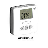
Mounting of thermostat with built-in sensor
The room sensor is used for comfort temperature regulation in
rooms. The thermostat should be mounted on the wall approx.
1.5 m above the floor in such a way as to allow free air circulation
around it. Draughts and direct sunlight or other heat sources must
be avoided.
Fig. 4 - Opening the thermostat
1. Slide the power button down to O “0”.
2. Release the front cover ONLY by inserting a small screwdriver
into the slot at the centre of the bottom side of the front cover to
press and hold the catch securing the front cover.
3. Then carefully pull the front cover away, initially from the
lower part of the thermostat, then from the upper part of the
thermostat.
Fig. 5 - Connections
Connect the wires in accordance with the diagram. The wires must
be connected as follows:
Term. 1: Neutral (N)
Term. 2: Live (L)
Term. 3-4: Output, max. 16 A
Term. X: Do not connect
Term. 5-6: External floor sensor
Fig. 6 + 7 - Mounting the thermostat
1. Mount the thermostat in the wall socket.
2. Fit the frame and carefully press the cover onto the thermostat
- starting with the upper part of the cover, then the lower part of
the cover. Ensure that both the power slide button on the cover
and the power switch pin in the thermostat are down.
OCD5/MCD5-1999 / OWD5/MWD5-1999 English