La Crosse WS-1913 User manual
- Category
- Weather stations
- Type
- User manual

1
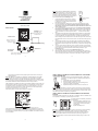
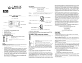
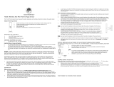
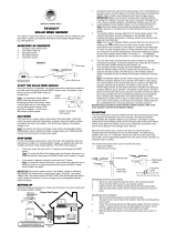
Cable connection between the wind sensor and
the thermo-hygro transmitter
OPTIONAL
Wireless transmission
at 915 MHz – Self-
Emptying Rain sensor
to weather station
Wireless transmission a
t
915 MHz - thermo-hygro
transmitter to weathe
r
station
Weather Cente
r
Wind Sensor
Rain Sensor (sold separately)
Thermo-hygro
Transmitter
Model WS-1913
WEATHER CENTER
Quick Setup Guide
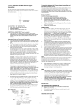
INITIAL SETUP:
2
Note: When putting the Weather Station into operation,
it is important to have them in close proximity (e.g. on a
table) while completing wiring and set-up of the system.
This step is important to allow testing of all components
for correct function before placing and mounting them at
their final destinations (See Positioning below).
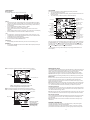
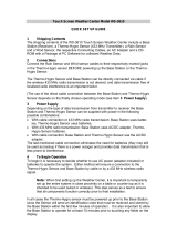
1. Unwind the cables of the Wind sensor. Connect
the Wind sensor to the Thermo-hygro transmitter
by plugging the connector head into the socket of
the Thermo-hygro sensor.
2. First insert the batteries into the Thermo-hygro sensor and optional rain sensor
(purchased separately) (See How to install and replace the batteries into the
Thermo-hygro sensor and How to install and replace the batteries into the rain
sensor (optional) below).
3. Then insert the batteries into the Weather Center (See How to install and replace
the batteries into the Weather Center below). Once the batteries are installed, all
segments of the LCD will light up. It will then display the time as 12:00, the date as
1.1.09, the weather icons, and air pressure value. "- - -" will be shown for outdoor
data.
4. The Weather Center will start receiving data from the transmitter. The transmission
reception icon will be blinking to indicate that the station is trying to get the thermo-
hygro transmitter data. The outdoor temperature, humidity and wind data should
then be displayed on the Weather Center. If this does not happen after 135 seconds,
the batteries will need to be removed from all units. You will have to start again from
step 2.
5. The transmitter reception icon is now blinking again to indicate that the station is
trying to get the rain sensor data. It will stop blinking once the rain sensor has been
detected. If this does not happen after 135 seconds, you will need to start again from
step 2.
6. You may need to check the cable for correct connection and all the components for
correct function by manually turning the wind-gauge by moving the wind-vane; tilting
the rain sensor to hear the impact of the internal moving seesaw, etc. (see
Positioning below).
7. Time and date must be manually set (See Manual Setting below).
8. After the Weather Center has been checked for correct function with regard to the
above points and found fit, the initial set up of the weather station system is finished
and the mounting of the system components can take place. It must be ensured
Socket for wind
sensor
3
however that all components work properly together at their chosen mounting or
standing locations.
Note: After batteries are installed in the transmitter, install the batteries in the weather
center to receive the signal from the transmitters as soon as possible. If the weather
center is powered more than 5 hours after the transmitter is powered, the weather center
will never receive the signal successfully from the transmitters. In this case, you will need
to reinstall the batteries for all the transmitters to redo the setup procedure.
After the batteries are installed, there will be synchronization between weather center and
the transmitters. At this time, the signal reception icon will be blinking. When the signal is
successfully received by the Weather Center, the icon will be switched on. (If it is not
successful, the icon will not be shown in LCD) This allows you to see whether the last
reception was successful (icon on) or not (icon off).
Short blinking of the icon shows that a reception is in progress.
If the signal reception is not successful on the first frequency (915MHz) for 45 seconds,
the frequency is changed to 920MHz and the learning is tried another 45 seconds. If still
not successful, the reception is tried for 45 seconds on 910MHz. This will also be done for
re-synchronization.
Transmitter signal reception icon
4
HOW TO INSTALL AND REPLACE THE BATTERIES INTO THE THERMO-
HYGRO TRANSMITTER
The outdoor Thermo-hygro transmitter works with 2 x AA IEC LR6,
1.5V batteries. To install and replace the batteries, please follow the
steps below:
1. Uninstall the rain cover of the transmitter.
2. Remove the battery compartment cover.
3. Insert the batteries, observing the correct polarity (see the
marking in the battery compartment).
4. Replace the battery cover and the rain cover onto the unit.
Note: When changing batteries in any of the units, all units need to be reset by following
the setup procedures. This is because a random security code is assigned by the thermo-
hygro sensor at start-up and this code must be received and stored by the weather center
in the first several minutes of power being supplied to it.
HOW TO INSTALL AND REPLACE THE BATTERIES IN THE WEATHER
STATION
The Weather Station works with 2 x C, IEC LR14, 1.5V batteries. When the batteries need
to be replaced, the low battery symbol will appear on the LCD.
To install or replace the batteries, please follow
the steps below:
1. Remove the battery compartment cover.
2. Insert the batteries observing the correct
polarity (see the marking in the battery
compartment).
3. Replace the battery cover.
Note: When changing batteries in any of the units, all units need to be reset by following
the setup procedures. This is because a random security code is assigned by the
transmitter and rain sensor (optional) at start-up and this code must be received and
stored by the Weather Station in the first 90 seconds of power being supplied to it.
Note: The stored History record will not be kept after the battery change is done on the
weather station.

5
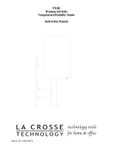
FUNCTION KEYS:
Weather Station:
The Weather Station has 4 easy-to-use function keys.
SET key
x Press and hold to enter manual setting modes: LCD contrast, Manual time setting,
12/24 hour time display, Calendar setting, ºC/ ºF temperature unit, Wind speed unit,
Rainfall unit, Pressure unit, Relative pressure reference setting, Weather tendency
threshold setting
x Press to toggle between the display of Mode 1 or Mode 2:
Mode1: "Wind speed + outdoor temp + rel. pressure"
Mode 2: "Gust + Dew Point temp + rainfall data (only if there is a rain sensor-
optional)"
(Mode 2 displayed will be shown for 30 seconds. Then it will return to normal display
x Press to activate the reset mode when MAX or MIN record is shown
+ key
x In display Mode 1, press to toggle the date, weekday, + date, Indoor temp, or sec
x In display Mode 2, press to toggle the Relative Pressure, 24 hour rainfall and Total
rainfall (if there is a rain sensor- optional).
x Press to adjust (increase) the level of different settings
x Press to confirm to reset the MIN/MAX record
HISTORY key
x Press to display the weather data history records or exit manual setting mode
MIN/MAX key
x Press to display MIN/MAX records of various weather data or adjust (decrease) the
level of different settings
MIN/MAX key
SET ke
y
+ key
HISTORY ke
y
6
Air pressure
history histogram
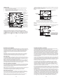
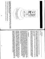
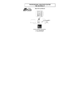
LCD SCREEN
The LCD screen is split into 3 sections displaying the following information:
1. Time and date/ indoor temp/ second
2. Wind data, outdoor temperature and humidity, dew point, weather forecast icon and
tendency indicator
3. Air pressure history, relative air pressure, rainfall data (optional)
When the signal from the transmitter/ or Rain sensor (optional) is successfully received by
the Weather Station, the
icon will be switched on. (If not successful, the icon will not
be shown on the LCD). User can therefore easily see whether the last reception was
successful (“ON”
icon) or not (“OFF” icon). On the other hand, the short blinking of
the
icon shows that a reception is being done at that time.
* In normal display user may press the SET key shortly to toggle between Mode1 and
Mode 2 display:
Wind speed / gust* in
mph, km/h, m/s
Calendar / indoor
temperature / seconds
display
Weather tendenc
y
indicato
r
Time display
Outdoor relative
humidity in %
Weather forecast
Icon
Relative air pressure /
24 hr rainfall / Total
rainfall display* (only if
there is a rain sensor
being used)
Wind Chill in
ƱC or ƱF
Low battery indicator
(weather station)
Transmitter signal
reception icon
Low battery
indicator #
(transmitter)
Outdoo
r
temperature
/ dew point*
in qC or qF
MI/MAX icons
HISTORY
icon
Low batter
y
indicator (rain
sensor - optional)
7
Mode 1: Wind speed, outdoor temperature, relative air pressure are shown.
Mode 2: Wind gust, dew point, and rainfall (optional) reading are shown.
Note: To view the rainfall data, press the + key after entering Mode 2 display.
Wind gust icon
Dew point icon
Rainfall icon
In Mode 2, this reception
icon is showing the
condition of the reception
of the signal from Rain
sensor (only if a rain
sensor is being used)
Wind speed icon
Outdoor temp
icon
Rel. Air Pressure icon
In Mode 1, this reception icon is showing the condition of the
reception of the signal from Thermo-hygro transmitter
Transmitter signal reception icon
8
MOUNTING THE UNITS:
Using 915MHz wireless transmission gives users little restriction on placement because all
units can be positioned virtually anywhere within a 330 ft / 100 meters radius of the base
station. Please ensure that the cable included in this set meets your distance
requirements (see accessories in the main user manual for adding extension cables).
Important: Ensure all signals can be received and/or all cable distances meet with your
requirements at the point of fixing particularly before you start drilling any mounting holes.
Wind sensor
Secure the main unit to the shaft of the mast holder using the single screw provided with
the front of the sensor (marked E) facing in the East-West direction otherwise wind
direction will not be accurate. Now fix the entire unit to a suitable mast using the U-bolt,
washers and nuts found in this set.
Note: For best results mount the wind sensor onto a mast to allow the wind to freely travel
from all directions to enable an accurate reading (ideal mast size should be from Ø
5
/
8
” to
1
1
/
4
”). Ensure that the cable of the wind sensor meets your distance requirements
Thermo-hygro Sensor
To wall mount the thermo-hygro sensor, fix the wall holder onto the desired wall (2 screws
are supplied), plug the sensor firmly into the wall holder and then carefully replace the rain
cover back over the thermo-hygro sensor.
Note: After mounting the units, should the weather data not be received, user may need to
remove the batteries from all units and redo the set-up procedures after about 5 minutes.
Rain sensor (optional)
The rain sensor should be mounted horizontally about 2-3ft off from the ground (or higher)
in an open area away from trees or other coverings to allow rain to fall naturally for an
accurate reading.
Note: For best results ensure the base is horizontal to allow maximum drainage of any
collected rain
WARRANTY INFORMATION
La Crosse Technology, Ltd provides a 1-year limited warranty on this product against
manufacturing defects in materials and workmanship.
This limited warranty begins on the original date of purchase, is valid only on products
purchased and used in North America and only to the original purchaser of this product.

9
To receive warranty service, the purchaser must contact La Crosse Technology, Ltd for
problem determination and service procedures. Warranty service can only be performed
by a La Crosse Technology, Ltd authorized service center. The original dated bill of sale
must be presented upon request as proof of purchase to La Crosse Technology, Ltd or La
Crosse Technology, Ltd’s authorized service center.
La Crosse Technology, Ltd will repair or replace this product, at our option and at no
charge as stipulated herein, with new or reconditioned parts or products if found to be
defective during the limited warranty period specified above. All replaced parts and
products become the property of La Crosse Technology, Ltd and must be returned to La
Crosse Technology, Ltd.
Replacement parts and products assume the remaining original warranty, or ninety (90)
days, whichever is longer. La Crosse Technology, Ltd will pay all expenses for labor and
materials for all repairs covered by this warranty. If necessary repairs are not covered by
this warranty, or if a product is examined which is not in need or repair, you will be
charged for the repairs or examination.
The owner must pay any shipping charges incurred in getting your La Crosse Technology,
Ltd product to a La Crosse Technology, Ltd authorized service center. La Crosse
Technology, Ltd will pay ground return shipping charges to the owner of the product to a
USA address only.
Your La Crosse Technology, Ltd warranty covers all defects in material and workmanship
with the following specified exceptions: (1) damage caused by accident, unreasonable use
or neglect (including the lack of reasonable and necessary maintenance); (2) damage
occurring during shipment (claims must be presented to the carrier); (3) damage to, or
deterioration of, any accessory or decorative surface; (4) damage resulting from failure to
follow instructions contained in your owner’s manual; (5) damage resulting from the
performance of repairs or alterations by someone other than an authorized La Crosse
Technology, Ltd authorized service center; (6) units used for other than home use (7)
applications and uses that this product was not intended or (8) the products inability to
receive a signal due to any source of interference.
This warranty covers only actual defects within the product itself, and does not cover the
cost of installation or removal from a fixed installation, normal set-up or adjustments,
claims based on misrepresentation by the seller or performance variations resulting from
installation-related circumstances.
LA CROSSE TECHNOLOGY, LTD WILL NOT ASSUME LIABILITY FOR INCIDENTAL,
CONSEQUENTIAL, PUNITIVE, OR OTHER SIMILAR DAMAGES ASSOCIATED WITH
10
THE OPERATION OR MALFUNCTION OF THIS PRODUCT. THIS PRODUCT IS NOT
TO BE USED FOR MEDICAL PURPOSES OR FOR PUBLIC INFORMATION. THIS
PRODUCT IS NOT A TOY. KEEP OUT OF CHILDREN’S REACH.
This warranty gives you specific legal rights. You may also have other rights specific to
your State. Some States do no allow the exclusion of consequential or incidental
damages therefore the above exclusion of limitation may not apply to you.
For warranty work, technical support, or information contact:
La Crosse Technology, Ltd
2817 Losey Blvd. S.
La Crosse, WI 54601
On the Web: www.lacrossetechnology.com/support
All rights reserved. This handbook must not be reproduced in any form, even in excerpts, or duplicated or
processed using electronic, mechanical or chemical procedures without written permission of the
publisher.
This handbook may contain mistakes and printing errors. The information in this handbook is regularly
checked and corrections made in the next issue. We accept no liability for technical mistakes or printing
errors, or their consequences.
All trademarks and patents are acknowledged.
11
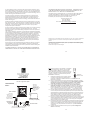
Modelo WS-1913
CENTRO CLIMÁTICO
Guía de configuración rápida
CONFIGURACIÓN
INICIAL:
Cable de conexión entre el sensor de viento y
transmisor con termómetro e higrómetro
OPCIONAL
Transmisión
inalámbrica a 915
MHz: sensor de lluvia
inalámbrico, con
vaciado automático,
p
ara la estación
climática
Transmisión
inalámbrica a 915
MHz: transmisor
con termómetro e
higrómetro, para la
estación climática
Centro climático
Sensor de viento
Sensor de lluvia
(se vende por separado)
Transmisor con
termómetro e
higrómetro
12
Nota: Al hacer funcionar el centro climático, es importante
tenerlo a corta distancia (por ejemplo, sobre una mesa)
mientras se finaliza el cableado y la configuración del
sistema. Este paso es importante para permitir probar que
todos los componentes funcionan correctamente antes de
colocarlos y montarlos en sus destinos finales (consulte
Colocación a continuación).
9. Desenrolle los cables del sensor de viento. Conecte
el sensor de viento al transmisor del termómetro e
higrómetro, enchufando el cabezal del conector en el socket del sensor del
termómetro e higrómetro.
10. Primero, inserte las baterías en el sensor del termómetro e higrómetro y el sensor
de lluvia opcional (se compra por separado) (consulte Cómo instalar y reemplazar
las baterías en el sensor del termómetro e higrómetro y Cómo instalar y
reemplazar las baterías en el sensor de lluvia (opcional) a continuación).
11. Luego, inserte las baterías en el centro climático (consulte Cómo instalar y
reemplazar las baterías en el centro climático a continuación). Una vez que las
baterías estén instaladas, se iluminarán todos los segmentos de la pantalla LCD.
Luego se mostrará la hora como las 12:00, la fecha como 1.1.09, los íconos del
clima y el valor de la presión del aire. Se mostrará "- - -" como datos del exterior.
12. El centro climático comenzará a recibir señales de datos desde el transmisor. El
ícono de recepción de la transmisión parpadeará para indicar que la estación está
intentando obtener los datos del transmisor del termómetro e higrómetro. Entonces
debería aparecer los datos de la temperatura exterior, la humedad y el viento en el
centro climático. Si esto no ocurre luego de 135 segundos, deberá retirar las
baterías de todas las unidades. Deberá comenzar de nuevo desde el paso 2.
13. El ícono de recepción del transmisor parpadeará ahora de nuevo para indicar que la
estación está intentando obtener los datos del sensor de lluvia. Dejará de parpadear
cuando se detecte el sensor de lluvia. Si esto no ocurre luego de 135 segundos,
deberá comenzar de nuevo desde el paso 2.
14. Es posible que deba revisar que el cable esté correctamente conectado y que todos
los componentes funcionen correctamente girando de forma manual el medidor de
viento al mover la tablilla de viento, inclinar el sensor de lluvia para escuchar el
impacto de la sube y baja moviéndose en el interior, etc. (consulte Colocación a
continuación).
15. Se debe configurar manualmente la hora y la fecha (consulte Configuración
manual a continuación).
Socket para
sensor de viento
Page is loading ...
Page is loading ...
Page is loading ...
-
 1
1
-
 2
2
-
 3
3
-
 4
4
-
 5
5
-
 6
6


La Crosse WS-1913 User manual
- Category
- Weather stations
- Type
- User manual
Ask a question and I''ll find the answer in the document
Finding information in a document is now easier with AI
in other languages
- español: La Crosse WS-1913 Manual de usuario
Related papers
Other documents
-
La Crosse Technology WS-1913IT Quick Setup Manual
-
 La Crosse Technology WS-9009U Quick Setup Manual
-
 La Crosse Technology Professional Remote Weather Station Operational Manual
-
 La Crosse Technology WS-9009U User manual
-
 La Crosse Technology TX22U User manual
-
 La Crosse Technology Tomorrow's Weather Today TX28U User manual
-
 Lacrosse WS-3610-SAL Quick start guide
-
 La Crosse Technology TX8U User manual
-
 La Crosse Technology WS-1610TWC-IT User manual
-
 La Crosse Technology OMO-M-12 User manual


