Soundstream Technologies 404s User manual
- Category
- Car audio amplifiers
- Type
- User manual

20
SOUNDSTREAM TECHNOLOGIES
120 Blue Ravine Road Folsom California 95630 USA
ph 916.351.1288 fax 916.351.0414
rev A - 4.25.96
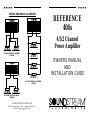
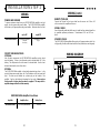
SERIES AND PARALLEL WIRING
2-4 ohm drivers in parallel
= 2 ohms
2-4 ohm drivers in series
= 8 ohms
4-4 ohm drivers in parallel
=1 ohm
1
REFERENCE
404s
4/3/2 Channel
Power Amplifier
OWNERS MANUAL
AND
INSTALLATION GUIDE

2
CONGRATULATIONS!
You now own the REFERENCE404s Amplifier, the product of an
uncompromising design and engineering philosophy. Your
Soundstream REFERENCE404s amplifier will outperform any other
amplifier in the world.
To maximize the performance of your system, we recommend that you
thoroughly acquaint yourself with its capabilities and features. Please
retain this manual and your sales and installation receipts for future
reference.
Soundstream amplifiers are the result of American craftsmanship and
the highest quality control standards, and when properly installed, will
provide you with many years of listening pleasure. Should your
amplifier ever need service or replacement due to theft, please record
the following information, which will help protect your investment.
Model and Serial # ____________________________________
Dealer’s Name _______________________________________
Date of Purchase _____________________________________
Installation Shop ______________________________________
Installation Date ______________________________________
CAUTION!
Prolonged listening at high levels may result in hearing loss. Even
though your new Soundstream REFERENCE404s amplifier sounds
better than anything you’ve ever heard, exercise caution to prevent
hearing damage.
19
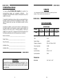
SERVICE
Your Soundstream REFERENCE404s amplifier is protected by a limited
warranty. Please read the enclosed warranty card.
SPECIFICATIONS
THD <0.1%
Signal to Noise >100 dB
Frequency Response 20 Hz to 20 kHz ± 0.5 dB
Stereo Separation >90 dB
Damping >200
Input Sensitivity 200 mV - 5.0 V
Input Impedance
12 kΩ
W x D x H:
13.0” x 9.8” x 2.25”
Dimensions
POWER
4 Ω Ω Stereo
(8 Ω Ω Bridged)
2 Ω Ω Stereo
(4 Ω Ω Bridged)
1 Ω Ω Stereo
(2 Ω Ω Bridged)
1/2 Ω Ω Stereo
(1 Ω Ω Bridged)
Watts
50 x 4 75 x 4 100 x 4 100 x 4
REFERENCE404s

18
PROTECTION CIRCUITRY
Your REFERENCE404s amplifier is protected against both overheating and
short circuits by means of the following circuits:
• Auto High Current™ power supply
• Main power supply fuses
• Circuit breaker on each channel
• Smart Power Supply Thermal Rollback activating at 85°C
• A fail-safe thermal protection circuit activating at 95°C.
Your amplifier also incorporates an innovative Fault Diagnosis system that
identifies a blown power supply fuse.
NOTE: If you experience blown main power supply fuses, DO NOT increase
values beyond the original fuse value! Doing so will void your warranty and
TROUBLESHOOTING
PROBLEM CAUSE
No sound and LEDs
are not lit
• no power or ground at amp
• no remote turn-on signal
• blown fuse near battery
Fault LED is lit
• amp power supply fuse is blown or missing
Repeatedly blown
amp fuse, frequent
activation of Smart
Power Supply Circuit
• speaker or leads may be shorted
• verify adequate amplifier ventilation
Channels 1,2,3 or 4
experiencing inter-
mittent output
• activation of the internal circuit breakers.
• check to make sure channels 1-4 are driving a
1/2 ohm per channel load or greater
• speaker or leads may be shorted
No output from
channels 3 & 4 with
1 pair of RCA inputs
• Select "Internal from ch's 1 & 2" on Ch 3 & 4
input on the bottom of the amplifier. (see
pages 14 - 17)
3
TABLE OF CONTENTS
Design Features .................................................................4 - 5
REFERENCE404s Diagram ...............................................6 - 7
Auto High Current™ Power Supply ......................................... 8
Selecting Input Modes ............................................................. 9
Wiring (with Diagram) .....................................................10 - 11
Installation and Mounting ...................................................... 12
Level Setting ......................................................................... 13
System Installation Diagrams ..........................................14 -17
Protection Circuitry ................................................................ 18
Troubleshooting .................................................................... 18
Service .................................................................................. 19
Specifications ........................................................................ 19

4
DESIGN FEATURES
• Uncompromising Design and Construction including mil-spec
glass epoxy circuit boards and high current custom gold-plated solid
brass connections that will accept up to 4 gauge power/ground wire.
• Auto High Current™ - Soundstream’s newest exclusive circuit which
automatically customizes your amplifier to its particular application—
High Current, low impedance loads (multiple subwoofers, less than 2
ohms mono) or High Power, higher impedance loads (2 ohms mono
and up).
• Coherent Stereo
TM
/Mixed Mono selection for either “pure” stereo
operation or mixed mono for simultaneous stereo and mono.
• Chassisink
TM
Darlington Power Array - Soundstream’s
“overbuilding” of the output section incorporates multiple output
transistors instead of a few for faster, stronger power delivery. The
transistors are sandwiched between the circuit board and the heatsink
in a design called Chassisink
TM
to ensure cool, efficient amplifier
operation.
• PowerGrid Power Supply Design - All power supply components
are located near one another, connected by thick, wide PCB traces,
which ensures rapid, high current delivery. The entire power supply is
isolated on one side of the circuit board while the audio stage is
located opposite it, guaranteeing minimal noise.
• Ultra-Low ESR Capacitance Bank - Multiple small input power
capacitors are used to provide a lower ESR (Equivalent Series
Resistance), which means more power in and out faster.
• Smart Thermal Rollback - Most amplifiers shut off when they get too
hot. In the unlikely event the REFERENCE404s amplifier reaches
85° C, it will gradually roll back its average power (without affecting
the dynamics). Once the amplifier has cooled off, it returns to full
power output. If overheating should continue, a second thermal
sensing protection circuit will shut off the amplifier if the heatsink
reaches 95° C.
• Unregulated Power Supply - 4 ohm power ratings are measured at
12 volts, meaning substantially greater output in the real world when
the vehicle is running, where voltages range from 13.2 to 14.4 volts.
17
SAMPLE SYSTEM #4
2 channels of high pass input with 2 channels of stereo output
2 channels of stereo low pass input with 1 bridged channel of output

16
SAMPLE SYSTEM #3
2 channels of input with 2 channels of bridged high pass output
External input to channels 3 & 4 with an external crossover
5
• Fault Monitor LED on the top panel notifies you of blown power
supply fuses.
• 1/2 ohm Drive Ability - The REFERENCE404s amplifier is designed
to drive virtually any load—all the way down to 1/2 ohm stereo (per
channel) or 1 ohm mono.
• Four Independent Dual Discrete Class A Drive Stages - Over six
times the drive current of most amps, which maintains performance
into low impedance loads.
• Drive Delay
TM
Muted Turn-on/off Circuit - A unique circuit which
completely eliminates any amplifier-related turn-on/off noises.
• Flexible Input Sensitivity accepts voltages from 200 mV to 5.0 V,
permitting maximum output from the amplifier with virtually any
source unit.

6
Reference404s
15
SAMPLE SYSTEM #2
2 channels of input with 4 stereo channels of high pass output
Internal input to channels 3 & 4 with an external crossover

14
SAMPLE SYSTEM #1
4 channels of input
4 channels of full range output
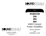
7
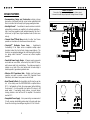
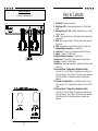
Key to Callouts
1. Fault LED - Indicates a blown fuse.
2. High Power LED - Indicates amplifier power on in "High Power"
mode.
3. Auto High Current™ LED - Indicates amplifier power on in "High
Current" mode.
4. +12V - Connected to a fuse or circuit breaker, then to the battery's
positive post.
5. GND - Main ground connection. Bolt to a clean chassis ground in
the vehicle.
6. REM - Remote turn-on input from the head unit. Accepts +12V.
7. Speaker Output Connections - Channels 1 & 2.
8. Input Level - Channels 1 & 2 independent input level controls.
9. Inputs - Channels 1 & 2 RCA inputs.
10. Speaker Output Connections - Channels 3 & 4.
11. Input Level - Channels 3 & 4 independent input level controls.
12. Inputs - Channels 3 & 4 RCA inputs.
13. Main Fuse - Main power supply fuse. Replace only with the same
value fuse.
14. Coherent Stereo™/Bridge Mono / Mixed Mono Switch -
Channels 1 & 2; Select "Bridge" for bridged mono operation (use
right channel input). Select "Stereo" for coherent stereo operation.
Select "Mixed Mono" for simultaneous stereo / bridged mono
operation.
15. Channels 3 & 4 Input Select - Selectable inputs from internal
(from channels 1 & 2) or external (from channels 3 & 4 local RCA
inputs).
16. Coherent Stereo™/Bridge Mono / Mixed Mono Switch -
Channels 3 & 4; Select "Bridge" for bridged mono operation (use
right channel input). Select "Stereo" for coherent stereo operation.
Select "Mixed Mono" for simultaneous stereo / bridged mono
operation.

8
OTHER COMMENTS:
If you blow fuses with the REFERENCE404s amplifier, it is likely that the
amplifier is seeing a dead short, either in the speaker wire or in the speaker
itself. Rectify the problem before blowing multiple fuses!
AUTO HIGH CURRENT™ POWER SUPPLY
The REFERENCE404s amplifier employs an extremely efficient Auto High
Current™ power supply (patent pending). This new power supply circuitry
automatically customizes your amplifier for optimum efficiency and power
output into virtually any impedance load. When other brand amplifiers are
driven at low impedances (i.e., 1 ohm or less), they shut down, squash
dynamics and power output (called current limiting), or waste huge amounts of
power (i.e., low efficiency). All of which reduce the "realworld" power the
amplifier can produce in the car. Soundstream's Auto High Current™ power
supply allows the REFERENCE404s amplifier to be one of two types of amps:
either producing maximum power at higher impedances (perfect for satellites)
or at lower impedances (usually with multiple subwoofers). This is done by
letting the amplifier's power supply continuously monitor the impedance of the
load the amplifier is driving. If the impedance drops too low, the power supply
will automatically switch into High Current mode. It will stay in this mode until
the amplifier is turned off. The next time it is powered up, it will be in the High
Power mode.
Unlike other amplifiers, Soundstream’s REFERENCE amplifiers can be
configured to drive virtually any impedance and make maximum power! The
major advantages of this power supply are:
• awesome dynamic power capabilities
• added continuous power with higher voltages
• increased amplifier efficiency and reliability
Because of the dynamic properties of most music, all audio components
should be able to react accordingly. Thanks to their unique power supplies,
the REFERENCE404s amplifier can comfortably exceed its rated power for
13
LEVEL SETTING
The input levels are adjusted by means of the input level controls located on
the front of the amplifier. This is a unique dual-stage circuit that adjusts both
level and gain. This topology maintains better Signal to Noise ratios even
when using sources with minimal output.
In the ideal situation, all components in the audio system reach maximum
undistorted output at the same time. The reason is because an amplifier will
only make what comes into it bigger. So, if you send it a distorted signal from
the head unit, the amplifier is going to amplify distorted information. The
same thing holds true if an outboard processor or crossover begins to distort
before you have maximum output from the amplifier. By setting all
components to reach clipping at the same time, you can maximize the output
of your system. For the REFERENCE404s amplifier, follow the below
procedure for the quickest, easiest means of setting the levels.
1. Turn the amp’s input levels to minimum position (fully counter-
clockwise).
2. Set source unit volume to approximately 3/4 of full volume.
3. While playing dynamic source material, slowly increase the amplifier’s
input level until a near maximum undistorted level is heard in the
system.
INSTALLATION STEP 4
NOTE: Even though the S/N ratio with low output sources is better with the
REFERENCE404s amplifier than others, your best combination of output level
and Signal to Noise ratio will be achieved when the input levels are set

12
INSTALLATION AND MOUNTING
1. AMPLIFIER LOCATION
The REFERENCE404s amplifier employs highly efficient circuitry and a unique
Chassisink
TM
design to maintain lower operating temperatures. Additional
cooling may be required if the amplifier is located in a tightly confined area or
when driving especially low impedance loads at extremely high levels.
When mounting the amplifier, it should be securely mounted to either a panel
in the vehicle or an amp board or rack that is securely mounted to the vehicle.
The mounting location should be either in the passenger compartment or in the
trunk of the vehicle, away from moisture, stray or moving objects, and major
electrical components. To provide adequate ventilation, mount the amplifier so
that there are at least two inches of freely circulating air above and to the sides
of it.
2. SWITCHES
Set the Coherent Stereo
TM
/ Bridged Mono / Mixed Mono and Channel 3 & 4
input switches to the appropriate positions (see pages 14 - 17).
3. MOUNTING THE AMPLIFIER
a. Using the amplifier as a template, mark the mounting surface.
b. Remove the amplifier and drill the holes.
c. Mount the amplifier to the surface using the provided hardware.
4. WIRING
a. Run and connect the audio signal and remote turn-on cables to the
amplifier from the source unit.
b. Carefully run the positive cable from the amplifier to a fuse or circuit
breaker within 18” of the battery.
c. Connect the fuse or circuit breaker to the battery. Leave the circuit
breaker off or the fuse out until everything is bolted down.
d. Secure the ground cable to a solid chassis ground on the vehicle. It may
be necessary to sand paint down to raw metal for a good connection.
e. Double check each and every connection!
f. Re-connect the fuse or circuit breaker.
5. POWER UP
Power up the system and look at the red "High Power" LED. There may be a
INSTALLATION STEP 3
NOTE: There may be a small spark when connecting the power and ground lead
to the amplifier for the first time. This is caused by current rushing into the
amplifier to charge the power supply capacitors, and is completely normal.
9
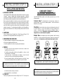
INSTALLATION STEP 1
COHERENT STEREO™ /
MIXED-MONO / BRIDGED MONO
The REFERENCE404s amplifier has the ability to operate in any one of the
following modes:
Coherent Stereo™ with identical left and right stereo channels for
maximum fidelity. Best choice for satellite speakers. Use this mode unless
Mixed-Mono is necessary.
Mixed-Mono in order to drive stereo and mono simultaneously; works well
for center channels. It can be used anytime you need a summed mono
channel. Somewhat sacrifices sonic accuracy as additional circuitry is
introduced to one channel. In Mixed-Mono, the left channel is inverted, see
diagram below or on the bottom of the amplifier.
Bridged Mono for dedicated single channel operation; ideal for driving
subwoofers. It is also used when large amounts of power are necessary for
single speakers. In bridged mono, only the right channel input is active.
In bridged mono, only the right channel input is active.
NOTE: If you intend to drive the REFERENCE404s amp in mono but have
stereo outputs from your crossover or source unit, you can put the switch in
Mixed-Mono but follow the normal wiring for Bridged Mono.

10
WIRING
POWER AND GROUND
To ensure maximum output from your REFERENCE404s amplifier, use high
quality, low-loss power and ground cables. The REFERENCE404s amplifier
will accept up to 4 gauge power and ground cables. Determine from the chart
up to 10’ up to 20’
REFERENCE404s
Soundstream Power40 or
Power80
(4 or 8 ga.)
Soundstream Power40
(4 ga.)
INSTALLATION STEP 2
Amplifier Amplifier Fuse Battery Fuse
REFERENCE404s
(2) 25 amp automotive 60 amp
REFERENCE404s Amplifier Fuse Values
CIRCUIT BREAKERS/FUSES
EXTERNAL
Like all audio components, the REFERENCE404s amplifier must be fused
near the battery. A fuse or circuit breaker must be located within 18” of the
battery. This will prevent a fire in the event of a shorted cable. See the chart
below to determine the correct fuse value.
INTERNAL
The REFERENCE404s amplifier is fused with automotive-type fuses. In the
event of blown power supply fuses, the “Fault” indicator on the front panel will
light. The fuses are accessible via a plastic plug on the bottom of the
amplifier. See the chart below to determine the fuse value. Never replace
the fuses with a higher value than what is supplied. This may result in
amplifier damage and will void the warranty!
11
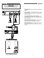
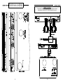
WIRING DIAGRAM
WIRING (cont.)
REMOTE TURN-ON
Connect the “Remote” to the turn-on lead from the source unit. When +12
volts is received, the amplifier will turn on.
SIGNAL CABLE
Use a high-quality cable that will be easy to install and has minimal signal loss
to guarantee optimum performance. Soundstream’s DL1 and SL1 are
ideal.
SPEAKER CABLE
The REFERENCE404s amplifier will accept up to 8 gauge speaker cable. Use
a high quality, flexible, multi-strand cable for best performance and longevity.
-
 1
1
-
 2
2
-
 3
3
-
 4
4
-
 5
5
-
 6
6
-
 7
7
-
 8
8
-
 9
9
-
 10
10


Soundstream Technologies 404s User manual
- Category
- Car audio amplifiers
- Type
- User manual
Ask a question and I''ll find the answer in the document
Finding information in a document is now easier with AI
Related papers
-
 Soundstream Technologies SA-80 User manual
-
 Soundstream Technologies 414s User manual
-
 Soundstream Technologies Granite 120.4 User manual
-
 Soundstream Technologies RUBICON 702 User manual
-
 Soundstream Technologies Class A 5.2 102 User manual
-
 Soundstream Technologies Angina A4 User manual
-
 Soundstream Technologies 805 User manual
-
 Soundstream Technologies 604 User manual
-
 Soundstream Technologies RUBICON 555 User manual
-
 Soundstream Technologies HRU. 2 User manual


Other documents
-
 Linear Power 992IQ Owner's Manual And Installation Manual
-
Soundstream Reference Series 160S Installation guide
-
-
-
-
-
-
-
-
Soundstream HUMAN REIGN HR 4 Owner's manual
