Sony Xplod CDX-M800 User manual
- Category
- Car video systems
- Type
- User manual
This manual is also suitable for

1
Ver 1.0 2003. 01
Model Name Using Similar Mechanism CDX-L410X/L490X
CD Drive Mechanism Type MG-393XC-121//K
Optical Pick-up Name KSS-721A
SERVICE MANUAL
US Model
Canadian Model
AEP Model
UK Model
E Model
CDX-M800
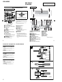
• The tuner and CD sections have no adjustments.
AUDIO POWER SPECIFICATIONS (US MODEL)
POWER OUTPUT AND TOTAL HARMONIC DISTORTION
23.2 watts per channel minimum continuous average power into
4 ohms, 4 channels driven from 20 Hz to 20 kHz with no more
than 5% total harmonic distortion.
CD player section
Signal-to-noise ratio 90 dB
Frequency response 10 – 20,000 Hz
Wow and flutter Below measurable limit
Tuner section
FM
Tuning range 87.5 – 107.9 MHz (US, Canadian model)
87.5 – 108.0 MHz (AEP, UK, E model)
Antenna terminal External antenna connector
Intermediate frequency 10.7 MHz/450 kHz
Usable sensitivity 9 dBf
Selectivity 75 dB at 400 kHz
Signal-to-noise ratio 67 dB (stereo),
69 dB (mono)
Harmonic distortion at 1 kHz
0.5% (stereo),
0.3% (mono)
Separation 35 dB at 1 kHz
Frequency response 30 – 15,000 Hz
AM (US, Canadian model)
Tuning range 530 – 1,710 kHz
Antenna terminal External antenna connector
Intermediate frequency 10.7 MHz/450 kHz
Sensitivity 30 µV
SPECIFICATIONS
MW/LW (AEP, UK, E model)
Tuning range MW: 531 – 1,602 kHz
LW: 153 – 279 kHz
Aerial terminal External aerial connector
Intermediate frequency 10.7 MHz/450 kHz
Sensitivity MW: 30 µV
LW: 40 µV
Power amplifier section
Outputs Speaker outputs (sure seal connectors)
Speaker impedance 4 – 8 ohms
Maximum power output 52 W × 4 (at 4 ohms)
General
Outputs Audio outputs (front/rear)
Subwoofer output (mono)
Power antenna relay
control terminal (US, Canadian model)
Power aerial relay
control terminal (AEP, UK, E model)
Power amplifier control
terminal
FM/AM COMPACT DISC PLAYER
US, Canadian Model
FM/MW/LW COMPACT DISC PLAYER
AEP, UK, E Model
– Continued on next page –
Sony Corporation
e Vehicle Company
Published by Sony Engineering Corporation
9-874-299-01
2003A0400-1
© 2003. 01

2
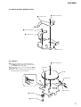
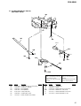
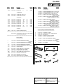
optical pick-up bloc
k
semi-fixed resistor
SERVICE NOTES
Inputs Telephone ATT control
terminal
Illumination control terminal (US, Canadian model)
BUS control input terminal
BUS audio input or AUX IN terminal
Antenna input terminal (US, Canadian model)
Aerial input terminal (AEP, UK, E model)
Tone controls US, Canadian model:
Bass ±10 dB at 62 Hz
Treble ±10 dB at 16 kHz
AEP, UK, E model:
Bass ±8 dB at 100 Hz
Treble ±8 dB at 10 kHz
Loudness +8 dB at 100 Hz
+2 dB at 10 kHz
Power requirements 12 V DC car battery
(negative ground)
Dimensions Approx. 178 × 50 × 186 mm
(7 1/8 × 2 × 7 3/8 in.)
(w/h/d)
Mounting dimensions Approx. 182 × 53 × 163 mm
(7 1/4 × 2 1/8 × 6 1/2 in.)
(w/h/d)
Mass Approx. 1.5 kg (2 lb. 10 oz.)
Supplied accessories Parts for installation and
connections (1 set)
Card remote commander
RM-X110 (US, Canadian model)
RM-X111 (AEP, UK, E model)
Note
This unit cannot be connected to a digital preamplifier or an equalizer.
Design and specifications are subject to change without
notice.
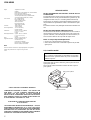
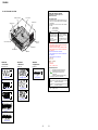
NOTES ON HANDLING THE OPTICAL PICK-UP BLOCK
OR BASE UNIT
The laser diode in the optical pick-up block may suffer electrostatic
breakdown because of the potential difference generated by the
charged electrostatic load, etc. on clothing and the human body.
During repair, pay attention to electrostatic breakdown and also use
the procedure in the printed matter which is included in the repair
parts.
The flexible board is easily damaged and should be handled with
care.
NOTES ON LASER DIODE EMISSION CHECK
The laser beam on this model is concentrated so as to be focused on
the disc reflective surface by the objective lens in the optical pick-
up block. Therefore, when checking the laser diode emission, ob-
serve from more than 30 cm away from the objective lens.
Notes on Chip Component Replacement
• Never reuse a disconnected chip component.
• Notice that the minus side of a tantalum capacitor may be dam-
aged by heat.
CAUTION
Use of controls or adjustments or performance of procedures
other than those specified herein may result in hazardous
radiation exposure.
If the optical pick-up block is defective, please replace the whole
optical pick-up block.
Never turn the semi-fixed resistor located at the side of optical
pick-up block.
US, Canadian model:
CDX-M800
SAFETY-RELATED COMPONENT WARNING!!
COMPONENTS IDENTIFIED BY MARK 0 OR DOTTED LINE
WITH MARK 0 ON THE SCHEMATIC DIAGRAMS AND IN
THE PARTS LIST ARE CRITICAL TO SAFE OPERATION.
REPLACE THESE COMPONENTS WITH SONY PARTS WHOSE
PART NUMBERS APPEAR AS SHOWN IN THIS MANUAL OR
IN SUPPLEMENTS PUBLISHED BY SONY.
ATTENTION AU COMPOSANT AYANT RAPPORT
À LA SÉCURITÉ!!
LES COMPOSANTS IDENTIFIÉS PAR UNE MARQUE 0 SUR LES
DIAGRAMMES SCHÉMATIQUES ET LA LISTE DES PIÈCES
SONT CRITIQUES POUR LA SÉCURITÉ DE FONCTIONNEMENT.
NE REMPLACER CES COMPOSANTS QUE PAR DES PIÈCES
SONY DONT LES NUMÉROS SONT DONNÉS DANS CE MANUEL
OU DANS LES SUPPLÉMENTS PUBLIÉS PAR SONY.

3
Notes on CD-R/CD-RW discs
• You can play CD-Rs (recordable CDs)/CD-RWs (rewritable CDs)
designed for audio use on this unit.
Look for these marks to distinguish CD-Rs/CD-RWs for audio
use.
These marks denote that a disc is not for audio use.
• Some CD-Rs/CD-RWs (depending on the equipment used for
its recording or the condition of the disc) may not play on this
unit.
• You cannot play a CD-R/a CD-RW that is not finalized
∗
.
∗ A process necessary for a recorded CD-R/CD-RW disc to be
played on the audio CD player.
stand
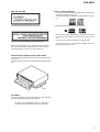
NOTE FOR THE OPENING OF THE FRONT PANEL
In this set, the front panel is lowered to below the bottom face when
it is opened.
When servicing the set, place it on a stand having a height of about
2 cm.
AEP, UK, E model:
This label is located on the bottom of the chassis.
This label is located on the drive unit’s internal chassis.
When replacing the chassis (T) of mechanism deck which have
the “CAUTION LABEL” attached, please be sure to put a new
CAUTION LABEL (3-223-913-11) to the chassis (T).
CDX-M800
TEST DISCS
This set can playback CD-R and CD-ROM discs. The following
test discs should be used to check the capability:
CD-R test disc TCD-R082LMT (Part No. J-2502-063-1)
CD-RW test disc TCD-W082L (Part No. J-2502-063-2)

4
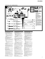
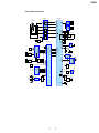
EXTENSION CABLE AND SERVICE POSITION
When repairing or servicing this set, connect the jig (extension cable)
as shown below.
•Connect the MAIN board (CNP301) and the SERVO board (CN1)
with the extension cable (Part No. J-2502-062-1).
CDX-M800
MAIN BOARD CNP301
SERVO BOARD CN1

5
TABLE OF CONTENTS
1. GENERAL
Location of Controls................................................................ 6
Connection example (US, Canadian Model)........................... 6
Connections (US, Canadian Model)........................................ 7
2. DISASSEMBLY
2-1. Front Panel Assy ................................................................. 8
2-2. CD Mechanism Block, Front Panel Assy............................ 9
2-3. Sub Panel (CD) Sub Assy ................................................... 9
2-4. Motor Block Assy, Cam (R) Assy ..................................... 10
2-5. Main Board ....................................................................... 10
2-6. Heat Sink ........................................................................... 11
2-7. Chassis (T) Sub Assy ........................................................ 11
2-8. Lever Section, In Self SW Board ...................................... 12
2-9. Servo Board....................................................................... 12
2-10. Shaft Roller Assy, Load SW Board................................... 13
2-11. Floating Block Assy .......................................................... 13
2-12. Optical Pick-up Block .......................................................14
3. PHASE ALIGNMENT
3-1. Arm (A-L) Assy, Arm (B-L) Assy ..................................... 15
3-2. Cam (L) ............................................................................. 15
3-3. Motor Block ...................................................................... 16
3-4. Alignment between Arm (A-L) Assy
and Arm (B-L) Assy .......................................................... 16
3-5. Arm (A-R) Assy, Arm (B-R) Assy .................................... 17
3-6. Cam (R) ............................................................................. 17
CDX-M800
4. DIAGRAMS
4-1. IC Pin Descriptions ...........................................................18
4-2. Block Diagram –CD Section–........................................... 21
4-3. Block Diagram –Tuner Section– ....................................... 22
4-4. Block Diagram –Display Section–.................................... 23
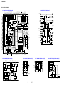
4-5. Circuit Boards Location .................................................... 24
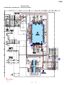
4-6. Schematic Diagram –CD Mechanism Section– ................ 25
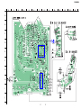
4-7. Printed Wiring Boards –CD Mechanism Section–............ 26
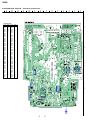
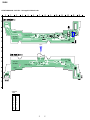
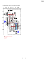
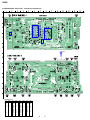
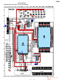
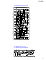
4-8. Printed Wiring Boards –Main Section– ............................ 28
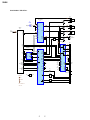
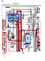
4-9. Schematic Diagram –Main Section (1/2)– ........................ 30
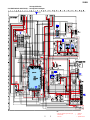
4-10. Schematic Diagram –Main Section (2/2)– ........................ 31
4-11. Printed Wiring Board –Sub Section– ................................ 32
4-12. Schematic Diagram –Sub Section– ................................... 33
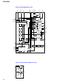
4-13. Printed Wiring Board –Display Section– .......................... 34
4-14. Schematic Diagram –Display Section–............................. 35
4-15. IC Block Diagrams............................................................ 36
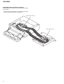
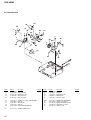
5. EXPLODED VIEWS
5-1. Chassis Section ................................................................. 39
5-2. Cam Section ......................................................................40
5-3. Main Board Section .......................................................... 41
5-4. Front Panel Section ...........................................................42
5-5. CD Mechanism Section (1) ............................................... 43
5-6. CD Mechanism Section (2) ............................................... 44
5-7. CD Mechanism Section (3) ............................................... 45
6. ELECTRICAL PARTS LIST......................................... 46

6
CDX-M800
4
Location of controls
Refer to the pages listed for details.
a SCRL (scroll) button
10
b DSPL (display mode change) button
10, 12
c Number buttons
(1) REP
11
(2) SHUF
11
To store stations/receive stored stations.
d EQ7 button
18
e MENU button
To display the menus.
f SOURCE (Power on/Radio/CD/MD*
1
/
AU X*
2
) button
To select the source.
g SEEK (</,) buttons
To skip tracks/fast-forward, reverse a track/
tune in stations automatically, find a station
manually/select a setting.
h SOUND button
16
i OFF (Stop/Power off) button
9, 21
j VOL (+/–) buttons
To turn up or down the volume.
k OPEN/CLOSE button
9
l MODE button
To change the operation.
m DSO button
19
n LIST button
13, 16
o DISC (M/m) buttons
To receive preset stations/change the disc*
3
,
skip albums*
4
/select a menu.
p ENTER button
To enter a setting.
q ATT button
17
*1
When an optional MD unit is connected.
*2
Available only when an optional Sony portable
device is connected to BUS AUDIO IN of the unit.
You cannot connect any optional CD/MD units at
the same time.
*3
When an optional CD/MD unit is connected.
*4
Available only when an optional CD unit with the
MP3 file control function is connected, and MP3 file
is played.
Card remote commander RM-X110
DISC
–
AT TOFF
SCRL
REP SHUF
DSPL
1
4
MODE
2
5
3
6
SOURCE
DISC
+
SEEK
+
SEEK
–
SOUND
ENTER
M
E
N
U
L
IS
T
EQ7 DSO
VO L
+
–
OPEN/CLOSE
DISC
–
SOURCE
DISC
+
SEEK
+
SEEK
–
In menu mode, the currently selectable button(s) of
these four are indicated with a “
v
” in the display.
Note
If the display disappears by pressing
(OFF)
, it cannot
be operated with the card remote commander unless
(SOURCE)
on the unit is pressed, or a disc is inserted
to activate the unit first.
Tip
Refer to “Replacing the lithium battery” for details on
how to replace the batteries (page 22).
(SEEK) (<):
to select
leftwards
(DISC) (M):
to select upwards
(DISC) (m):
to select downwards
(SEEK) (,):
to select
rightwards
SECTION 1
GENERAL
This section is extracted
from instruction manual.
(US, Canadian Model)
Connection example (US, Canadian Model)
5
The buttons on the unit share the same
functions as those on the card remote
commander.
a OPEN button 9
b Main display window
c IMAGE button 20
d qf Receptor for the card remote
commander
e qs RESET button 8
f OFF (Stop/Power off) button*
1
g SCRL (scroll) button
h DSPL (display mode change) button
i Sub display window
j SEEK/AMS (.m/M>) button
k MENU button
m LIST/CAT*
2
button
o
CLOSE (front panel close) button
9
p SOURCE button
q MODE button
r VOL (–/+) button
s DSO button
t EQ7 button
u SOUND button
v DISC (+/–) buttons
w ENTER button
x Z (eject) button 9
Main display side
Operation side
CDX-M800
continue to ne
xt page
t
Connection example (2)
Notes
(2-A)
• Be sure to connect the ground cord before connecting
the amplifier.
• If you connect an optional power amplifier and do not
use the built-in amplifier, the beep sound will be
deactivated.
Tip
(2-B- )
For connecting two or more CD/MD changers, the source
selector XA-C30 (optional) is necessary.
Exemple de raccordement (2)
Remarques
(2-A)
• Raccordez d’abord le fil de masse avant de raccorder
l’amplificateur.
•Si vous raccordez un amplificateur de puissance en
option et que vous n’utilisez pas l’amplificateur intégré,
le bip sonore est désactivé.
Conseil
(2-B- )
Dans le cas du raccordement de deux changeurs de
CD/MD ou plus, le sélecteur de source XA-C30 (en option)
est requis.
Ejemplo de conexiones (2)
Notas
(2-A)
• Asegúrese de conectar primero el cable de puesta a masa
antes de realizar la conexión al amplificador.
•Si conecta un amplificador de potencia opcional y no utiliza
el incorporado, los pitidos se desactivarán.
Consejo
(2-B- )
Cuando desee conectar dos o más cambiadores de CD/MD,
necesitará un selector de fuente XA-C30 (opcional).
BUS CONTROL IN
BUS AUDIO IN
Source selector*
Sélecteur de source*
Selector de fuente*
XA-C30
*
not supplied
non fourni
no suministrado
2
A
B
AUDIO OUT
FRONT
AUDIO OUT
REAR
BUS AUDIO IN
BUS CONTROL IN
SUB OUT (MONO)

7
CDX-M800
Connections (US, Canadian Model)
L
R
BUS
AUDIO IN
AUDIO OUT
REAR FRONT
AUX IN
Schéma de raccordement (3)
1
À un point métallique de la voiture
Branchez d‘abord le fil de masse noir et, ensuite, les fils d‘entrée
d‘alimentation jaune et rouge.
2
Vers le fil de commande de l‘antenne électrique ou le fil
d‘alimentation de l‘amplificateur d‘antenne
Remarques
• Il n'est pas nécessaire de raccorder ce fil s'il n'y a pas
d'antenne électrique ni d'amplificateur d'antenne, ou avec
une antenne télescopique manuelle.
•Si votre voiture est équipée d'une antenne FM/AM intégrée
dans la vitre arrière/latérale, voir “Remarques sur les fils de
commande et d'alimentation”.
3
Au niveau du AMP REMOTE IN de l’amplificateur de
puissance en option
Ce raccordement s’applique uniquement aux amplificateurs. Le
branchement de tout autre système risque d’endommager
l’appareil.
4
Vers le cordon de liaison d’un téléphone de voiture
5
Vers le connecteur du signal d’éclairage de la voiture
Raccordez d‘abord le fil de masse noir à un point métallique de
la voiture.
6
À la borne +12 V qui est alimentée quand la clé de contact
est sur la position accessoires
Remarques
•S'il n'y a pas de position accessoires, raccordez la borne
d'alimentation (batterie) +12 V qui est alimentée en
permanence.
Raccordez d‘abord le fil de masse noir à un point métallique
de la voiture.
•Si votre voiture est équipée d'une antenne FM/AM intégrée
dans la vitre arrière/latérale, voir “Remarques sur les fils de
commande et d'alimentation”.
7
À la borne +12 V qui est alimentée en permanence
Raccordez d‘abord le fil de masse noir à un point métallique de
la voiture.
Remarques sur les fils de commande et d'alimentation
• Le fil de commande de l’antenne électrique (bleu) fournit une
alimentation de + 12 V CC lorsque vous mettez la radio sous
tension.
• Lorsque votre voiture est équipée d’une antenne FM/AM intégrée
dans la vitre arrière/latérale, raccordez la sortie de commande de
l’antenne (bleu) ou l’entrée d’alimentation des accessoires (rouge)
à la borne de l’amplificateur d’antenne existant. Pour plus de
détails, consultez votre détaillant.
• Une antenne électrique sans boitier de relais ne peut pas être
utilisée avec cet appareil.
Raccordement pour la conservation de la mémoire
Lorsque le fil d’entrée d’alimentation jaune est raccordé, le circuit
de la mémoire est alimenté en permanence même si la clé de
contact est sur la position d’arrêt.
Remarques sur le raccordement des haut-parleurs
•Avant de raccorder les haut-parleurs, mettez l’appareil hors
tension.
•Utilisez des haut-parleurs ayant une impédance de 4 à 8 ohms
avec une capacité électrique adéquate pour éviter de les
endommager.
• Ne raccordez pas les bornes du système de haut-parleur au châssis
de la voiture et ne raccordez pas les bornes du haut-parleur droit
à celles du haut-parleur gauche.
• Ne raccordez pas le câble de masse de cet appareil à la borne
négative (–) de l’enceinte.
•N’essayez pas de raccorder les haut-parleurs en parallèle.
• Raccordez uniquement des haut-parleurs passifs. Le raccordement
de haut-parleurs actifs (avec amplificateurs intégrés) aux bornes
des haut-parleurs peut endommager l’appareil.
•Pour éviter tout dysfonctionnement, n’utilisez pas les fils des haut-
parleurs intégrés installés dans votre voiture si l’appareil partage
un fil négatif commun (–) pour les haut-parleurs droit et gauche.
• Ne raccordez pas entre eux les cordons des haut-parleurs de
l’appareil.
Remarque sur le raccordement
Si les enceintes et l’amplificateur ne sont pas raccordés
correctement, le message “Failure” s’affiche. Dans ce cas, assurez-
vous que les enceintes et l’amplificateur sont bien raccordés.
3
BUS AUDIO IN
/
AUX IN
*
5
Source selector
(not supplied)
Sélecteur de source
(non fourni)
Selector de fuente
(no suministrado)
XA-C30
2
6
7
4
AMP REM
ANT REM
4
Max. supply current 0.3 A
Courant max. fourni 0,3 A
Corriente máx. de alimentación de 0,3 A
Fuse (10 A)
Fusible (10 A)
Fusible (10 A)
Red
Rouge
Rojo
Yellow
Jaune
Amarillo
Black
Noir
Negro
Blue
Bleu
Azul
Blue/white striped
Rayé bleu/blanc
Con rayas azules y blancas
White
Blanc
Blanco
Green
Vert
Verde
Purple
Mauve
Morado
White/black striped
Rayé blanc/noir
Con raya blanca/negra
Gray/black striped
Rayé gris/noir
Con raya gris/negra
Green/black striped
Rayé vert/noir
Con raya verde/negra
Purple/black striped
Rayé mauve/noir
Con raya violeta/negra
BUS
CONTROL IN
AUDIO OUT
FRONT
Gray
Gris
Gris
AUDIO OUT
REAR
Supplied with the CD/MD changer
Fourni avec le changeur de CD/MD
Suministrado con el cambiador de CD/MD
3
Left
Gauche
Izquierdo
Right
Droit
Derecho
Left
Gauche
Izquierdo
Right
Droit
Derecho
Light blue
Bleu ciel
Azul celeste
Max. supply current 0.1 A
Courant d’alimentation max. 0,1 A
Corriente máx. de alimentación de 0,1 A
ATT
1
SUB OUT (MONO)
*
1
Diagrama de conexión (3)
1
A una superficie metálica del automóvil
Conecte primero el cable de puesta a masa negro, y después los
cables amarillo y rojo de entrada de alimentación.
2
Al cable de control de la antena motorizada o al cable de
fuente de alimentación del amplificador de antena
Notas
•Si no se dispone de antena motorizada ni de amplificador de
antena, o se utiliza una antena telescópica accionada
manualmente, no será necesario conectar este cable.
•Si el automóvil incorpora una antena de FM/AM en el cristal
trasero o lateral, consulte “Notas sobre los cables de control y
de fuente de alimentación”.
3
Para conectar a AMP REMOTE IN del amplificador de
potencia opcional
Esta conexión es sólo para amplificadores.
La conexión de cualquier otro sistema puede dañar la unidad.
4
Al cable de interfaz de un teléfono para automóvil
5
A una señal de iluminación del automóvil
Asegúrese de conectar primero el cable de tierra negro a una
superficie metálica del automóvil.
6
Al terminal de alimentación de +12 V que recibe energía en
la posición de accesorio del interruptor de la llave de
encendido
Notas
•Si no hay posición de accesorio, conéctelo al terminal de
alimentación (batería) de +12 V que recibe energía sin
interrupción.
Asegúrese de conectar primero el cable de tierra negro a una
superficie metálica del automóvil.
•Si el automóvil incorpora una antena de FM/AM en el cristal
trasero/lateral, consulte “Notas sobre los cables de control y de
fuente de alimentación”.
7
Al terminal de alimentación de +12 V que recibe energía sin
interrupción
Asegúrese de conectar primero el cable de tierra negro a una
superficie metálica del automóvil.
Notas sobre los cables de control y de fuente de alimentación
•El conductor de control de la antena motorizada (azul) suministrará
+ cc 12 V cuando conecte la alimentación del sintonizador.
•Si el automóvil dispone de una antena de FM/AM incorporada en el
cristal trasero o lateral, conecte el cable de control de antena
motorizada (azul) o el cable de entrada de alimentación auxiliar
(rojo) al terminal de alimentación del amplificador de antena
existente. Para obtener información detallada, consulte a su
proveedor.
• Con esta unidad no es posible utilizar una antena motorizada sin
caja de relé.
Conexión para protección de la memoria
Si conecta el conductor de entrada amarillo, el circuito de la memoria
recibirá siempre alimentación, aunque ponga la llave de encendido
en la posición OFF.
Notas sobre la conexión de los altavoces
• Antes de conectar los altavoces, desconecte la alimentación de la
unidad.
•Utilice altavoces con una impedancia de 4 a 8
Ω
con la capacidad de
potencia adecuada para evitar que se dañen.
• No conecte los terminales de altavoz al chasis del automóvil, ni
conecte los terminales del altavoz derecho con los del izquierdo.
• No conecte el cable de puesta a masa de esta unidad al terminal
negativo (–) del altavoz.
• No intente conectar los altavoces en paralelo.
• Conecte solamente altavoces pasivos. Si conecta altavoces activos
(con amplificadores incorporados) a los terminales de altavoz,
puede dañar la unidad.
•Para evitar fallos de funcionamiento, no utilice los cables de altavoz
incorporados instalados en el automóvil si su unidad comparte un
cable negativo común (–) para los altavoces derecho e izquierdo.
• No conecte los cables de altavoz de la unidad entre sí.
Nota sobre la conexión
Si el altavoz y el amplificador no están conectados correctamente,
aparecerá “Failure” en la pantalla.
Si es así, compruebe la
conexión de ambos dispositivos.
Orange/white striped
Rayé orange/blanc
Con rayas naranjas y blancas
5
ILLUMINATION
*
4
*
1
*
1
RCA pin cord (not supplied)
Cordon à broche RCA (non fourni)
Cable con terminales RCA (no
suministrado)
*
2
Supplied with XA-C30
Fourni avec le XA-C30
Suministrado con el XA-C30
*
3
Auxiliary optional equipment such as
portable DVD player (not supplied)
Appareil auxiliaire en option, par
exemple un lecteur de DVD (non
fourni)
Equipo opcional auxiliar como un
reproductor de DVD portátil (no
suministrado)
*
4
Supplied with the auxiliary equipment
Fourni avec l’appareil auxiliaire
Suministrado con el equipo auxiliar
*
5
Be sure to match the color-coded code
for audio to the appropriate jacks from
the unit. If you connect an optional CD/
MD unit, you cannot use AUX IN
terminal.
Veillez à faire correspondre le code
couleur audio aux fiches de l’appareil.
Si vous raccordez un appareil CD ou
MD en option, vous ne pouvez pas
utiliser la borne AUX IN.
Asegúrese de hacer coincidir el código
codificado con colores para audio con
las tomas apropiadas de la unidad.
Si
conecta una unidad de CD/MD
opcional, no podrá utilizar el terminal
AUX IN.
*
2
from car antenna
à partir de l’antenne de la voiture
desde la antena del automóvil
*
3
Connection diagram (3)
1
To a metal surface of the car
First connect the black ground lead, then connect
the yellow and red power input leads.
2
To the power antenna control lead or power
supply lead of antenna booster amplifier
Notes
• It is not necessary to connect this lead if there is no
power antenna or antenna booster, or with a
manually-operated telescopic antenna.
•When your car has a built-in FM/AM antenna in
the rear/side glass, see “Notes on the control and
power supply leads.”
3
To AMP REMOTE IN of an optional power
amplifier
This connection is only for amplifiers. Connecting
any other system may damage the unit.
4
To the interface cable of a car telephone
5
To a car’s illumination signal
Be sure to connect the black ground lead to a metal
surface of the car.
6
To the +12 V power terminal which is energized
in the accessory position of the ignition key
switch
Notes
• If there is no accessory position, connect to the +12
V power (battery) terminal which is energized at
all times.
Be sure to connect the black ground lead to a
metal surface of the car.
•When your car has a built-in FM/AM antenna in
the rear/side glass, see “Notes on the control and
power supply leads.”
7
To the +12 V power terminal which is energized
at all times
Be sure to connect the black ground lead to a metal
surface of the car.
Notes on the control and power supply leads
• The power antenna control lead (blue) supplies +12 V
DC when you turn on the tuner.
•When your car has built-in FM/AM antenna in the rear/
side glass, connect the power antenna control lead
(blue) or the accessory power input lead (red) to the
power terminal of the existing antenna booster. For
details, consult your dealer.
•A power antenna without relay box cannot be used
with this unit.
Memory hold connection
When the yellow power input lead is connected, power
will always be supplied to the memory circuit even when
the ignition key is turned off.
Notes on speaker connection
• Before connecting the speakers, turn the unit off.
•Use speakers with an impedance of 4 to 8 ohms, and
with adequate power handling capacities to avoid its
damage.
•Do not connect the speaker terminals to the car
chassis, or connect the terminals of the right speakers
with those of the left speaker.
•Do not connect the ground lead of this unit to the
negative (–) terminal of the speaker.
•Do not attempt to connect the speakers in parallel.
•Connect only passive speakers. Connecting active
speakers (with built-in amplifiers) to the speaker
terminals may damage the unit.
•To avoid a malfunction, do not use the built-in speaker
wires installed in your car if the unit shares a common
negative (–) lead for the right and left speakers.
•Do not connect the unit’s speaker cords to each other.
Note on connection
If speaker and amplifier are not connected correctly,
“Failure” appears in the display. In this case, make sure
the speaker and amplifier are connected correctly.

8
CDX-M800
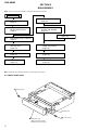
SECTION 2
DISASSEMBLY
Note : This set can be disassemble according to the following sequence.
Note : Follow the disassembly procedure in the numerical order given.
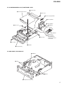
2-1. FRONT PANEL ASSY
2-1. FRONT PANEL ASSY
(Page 8)
2-2. CD MECHANISM BLOCK,
FRONT PANEL ASSY
(Page 9)
2-7. CHASSIS (T) SUB ASSY
(Page 11)
2-8. LEVER SECTION,
IN SELF SW BOARD
(Page 12)
2-10. SHAFT ROLLER ASSY,
LOAD SW BOARD
(Page 13)
2-11. FLOATING BLOCK ASSY
(Page 13)
2-12. OPTICAL PICK-UP BLOCK
(Page 14)
SET
2-9. SERVO BOARD
(Page 12)
2-5. MAIN BOARD
(Page 10)
2-6. HEAT SINK
(Page 11)
2-3. SUB PANEL (CD) SUB ASSY
(Page 9)
2-4. MOTOR BLOCK ASSY,
CAM (R) ASSY
(Page 10)
1
screw (panel)
flexible board
3
4
front panel assy
(Take care not to pull the
flexible board excessively)
2
screw (panel)

9
CDX-M800
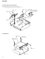
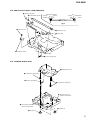
2-2. CD MECHANISM BLOCK, FRONT PANEL ASSY
2-3. SUB PANEL (CD) SUB ASSY
2
PTT 2.6x4
4
CNP301
1
PTT 2.6x6
3
PTT 2.6x4
5
CD mechanism block
7
bracket (CD)
6
PTT 2.6x6
8
tension spring (flexible)
flexible board
9
slider (flexible)
slider (flexible)
0
cover (flexible)
qa
CNP909
Note: When installing
the flexible board,
make the board slack
as illustrated.
qs
front panel assy
4
sub panel (CD) sub assy
2
claws
1
CNP805
3
claws

10
CDX-M800
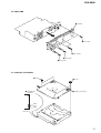
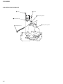
2-4. MOTOR BLOCK ASSY, CAM (R) ASSY
Note : Install the motor block assy and cam (R) assy in this roder.
For phase alignment between cams (L) and (R), see page 15 and 17.
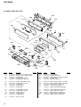
2-5. MAIN BOARD
1
PTT 2.6x6
4
PTT 2.6x6
5
motor block assy
2
cam (R) assy
3
CNP902
A
Note: Install the cam (R) assy wit
h
the cam fully rotated in the
direction of the arrow
A
.
4
PTT 2.6x6
ground point
3
PTT 2.6x6
ground point
1
PTT 2.6x6
5
MAIN board
2
PTT 2.6x
6

11
CDX-M800
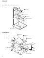
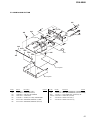
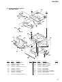
2-6. HEAT SINK
2-7. CHASSIS (T) SUB ASSY
5
heat sink
2
PTT 2.6x6
4
PTT 2.6x
6
3
PTT 2.6x12
1
PTT 2.6x6
4
chassis (T) sub assy
3
P 2x3
2
P 2x3
1
Unsolder the
lead wires.
black
red
white

12
CDX-M800
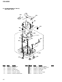
2-8. LEVER SECTION, IN SELF SW BOARD
2-9. SERVO BOARD
4
claws
2
IN SELF SW board
7
lever (L)
3
tension spring (LR)
6
lever (R)
5
guide (disc)
1
special screw
6
special screws
1
CN3
2
Removal the solders.
4
P 2x3
5
loading motor assy
8
SERVO board
7
special screw
9
FLEXIBLE board
optical pick-up block
3
Unsolder the
lead wires.
black
yellow

13
CDX-M800
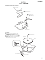
2-10. SHAFT ROLLER ASSY, LOAD SW BOARD
2-11. FLOATING BLOCK ASSY
Fig. 1
1
tension spring (RA)
2
arm (roller)
3
retaining ring (RA)
4
shaft retainer (roller)
5
shaft roller assy
6
special screw
7
LOAD SW board
retaining
ring (RA)
arm
arm
washer
washer
shaft retainer
(roller)
shaft retainer (roller)
1
tension spring (KF1)
7
compression spring (FL)
6
floating block assy
8
compression spring (FL)
4
Fit lever (D) in the
direction of the arrow.
2
damper (T)
3
damper (T)
5
Turn loading ring in the
direction of the arrow.

14
CDX-M800
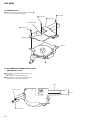
2-12. OPTICAL PICK-UP BLOCK
1
P 2x3
4
screw
5
plate spring (feed)
6
shaft (feed) assy
2
sled motor assy
3
optical pick-up block

15
CDX-M800
cam (L
)
arm (A-L) assy
arm (B-L) assy
C
A
B
3
type-E stop ring 1.5
hole (large)
line
SECTION 3
PHASE ALIGNMENT
3-1. ARM (A-L) ASSY, ARM (B-L) ASSY
3-2. CAM (L)
1 Move the arm (B-L) assy in the direction of the
arrow A and the arm (A-L) assy in the direction of
the arrow B fully (full open state).
2 Align the hole (large) on the cam (L) with part C and
install the cam.
4 Tu rn the cam (L) clockwise and counterclockwise to
verify that both the arms are operated.
4
type-E stop ring 1.5
2
type-E stop ring 1.5
1
arm (B-L) ass
y
3
arm (A-L) assy
bracket (L) assy

16
CDX-M800
3-3. MOTOR BLOCK
3-4. ALIGNMENT BETWEEN ARM (A-L) ASSY
AND ARM (B-L) ASSY
1 Turn the cam (L) and position the cam so that part A
does not touch the SW board SW900.
1 Input 9V DC to the motor terminal until the cam (L)
stops rotating.
Take care to avoid overload of the motor.
2 Verify that the arm (A-L) assy and arm (B-L) assy
are positioned as shown below (full open).
3
PTT 2.6x6
4
PTT 2.6x6
5
PTT 2.6x6
2
motor block
SWITCH board
SW900
cam (L
)
A
motor
GND
arm (B-L) assy
arm (A-L) assy
DC 9
V
+B

17
CDX-M800
3-6. CAM (R)
3-5. ARM (A-R) ASSY, ARM (B-R) ASSY
1 Move the arm (B-R) assy in the direction of the
arrow A and the arm (A-R) assy in the direction of
the arrow B fully (full open state).
2 Align the hole (large) on the cam (R) with part C and
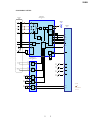
install the cam.
4 Tu rn the cam (R) clockwise and counterclockwise to
verify that both the arms are operated.
bracket (R) ass
y
3
arm (A-R) assy
4
type-E stop ring 1.5
2
type-E stop ring 1.5
1
arm (B-R) assy
3
type-E stop ring 1.5
5
oil damper
6
screw (P 2x4)
cam (R)
B
A
C
arm (B-R) assy
hole (large)
line
arm (A-R) assy

18
CDX-M800
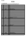
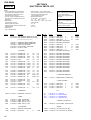
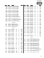
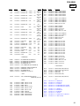
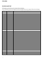
4-1. IC PIN DESCRIPTIONS
• IC303 M30626FHPGP-052 (US, Canadian model) (SYSTEM CONTROL) (MAIN Board (2/2))
• IC303 M30626FHPGP-053 (AEP, UK, E model) (SYSTEM CONTROL) (MAIN Board (2/2))
Pin No. Pin Name I/O Pin Description
1 SIRCS I Remote control data input
2 FP CTRL O Front panel open/close speed control signal
3 CD SO/TSO O CD servo serial data output
4 CD SI/TSI I CD servo serial data input
5 CD CKO/TCKO O CD servo serial clock output
6 BYTE I L fixed terminal
7 CNVSS I Flash write-in signal input
8 XIN I Sub clock signal input (32kHz)
9 XOUT O Sub clock signal output (32kHz)
10 RESET I CPU reset signal input
11 OSC OUT O Main clock signal output (6MHz)
12 VSS — Ground
13 OSC IN I Main clock signal input (6MHz)
14 VCC1 — Power supply pin (+5V)
15 NMI I Non maskable interrupt signal input
16 CD PACK I CD text pack synchronized signal input
17 DAVN I RDS data acquisition detect signal
18 BU IN I Back-up power detect signal
19 NS MASK O Not used. (Open)
20 BEEP O Beep signal output
21 FLW IN I OSC frequency shift signal for DC/DC conv.
22 NCO O Not used. (Open)
23 SA CLK O Spectrum analyzer clock signal output
24 TEL ATT I telephone mute detect signal input
25 ATT O Mute signal output
26 VOL ATT O Electronic volume mute signal output
27 I2C CKO O Tuner/E-volume BUS clock output
28 I2C SIO O Tuner/E-volume BUS data output
29 UNI SO O SONY BUS data output
30 UNI SI I SONY BUS data input
31 UNI CKO O SONY BUS clock output
32 TUNER ATT O Tuner attenuate signal output
33 EESIO I/O EEPROM data input/output
34 EECKO O EEPROM clock output
35 NCO O Not used. (Open)
36 ADSO1 O Not used. (Open)
37 ADSO2 O Not used. (Open)
38 NCO O Not used. (Open)
39 HOLD I Flash write-in signal input
40 AMP DIAG I Amplifier diagnosis signal input
41 AMP STB O Amplifier strobe signal output
42 AMP ON O Not used. (Open)
43 TUNER ON O Not used. (Open)
44 WRI/WR I Flash write-in signal input
45 CD LIMIT I CD limit detect signal input
46 CD D SW I CD disc SW detect signal input
47 CD PH1 I CD PH1 detect signal input
48 CD INSW/PH2 I CD IN SW/PH2 detect signal input
49 PH3 I CD PH3 detect signal input
50 DST SEL1 I Destination select signal input
SECTION 4
DIAGRAMS

19
CDX-M800
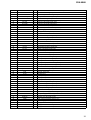
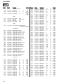
Pin No. Pin Name I/O Pin Description
51 DST SEL2 I Destination select signal input
52 CD LM LO O CD loading motor control signal output
53 CD LM EJ O CD eject motor control signal output
54 CD RST O CD servo reset signal output
55 CD AO O CD servo command/parameter discri. output
56 CD STB O CD servo data strobe signal output
57 CD TSTB O CD servo text strobe signal output
58 CD RFOK I CD servo RFOK signal input
59 CD XTALEN O CD servo crystal OSC control signal output
60 VCC2 — Power supply pin (+5V)
61 RESET OUT O Display CPU reset signal output
62 VSS — Ground
63 TEST IN I Test mode setting detect signal input
64 BUS ON O BUS ON control signal output
65 SYS RST O System reset signal output
66 BUS/AUX O BUS/AUX select control signal output
67 LINK OFF O Link OFF control signal output
68 ACC IN I Accessory key ON detect signal input
69 ILL IN I Ilumination line detect signal input
70 RC IN1 I Rotary commander signal input 1
71 NCO O Not used. (Open)
72 CD SELF SW I CD self SW detect signal input
73 TU ATT IN I Tuner mute control signal input
74 CLOSE SW I Front panel close detect signal input
75 OPEN SW I Front panel open detect signal input
76 I-DET I Front panel current detect signal input
77 MOT– O Front panel open/close control signal output
78 MOT+ O Front panel open/close control signal output
79 ROMC EN I ROM correction enable signal input
80 QUALITY I Tuner noise detect signal input
81 MPTH I Tuner multi-path signal input
82 VSM I S-meter signal input
83 SA IN I SA data input
84 KEY IN1 I Key signal input 1
85 KEY IN0 I Key signal input 0
86 RC IN0 I Rotary commander signal input 0
87 KEY ACK2 I Key acknowledge detect signal input 2
88 KEY ACK0 I Key acknowledge detect signal input 0
89 KEY ACK1 I Key acknowledge detect signal input 1
90 OPEN KEY I Open key detect signal input
91 RAM BU I RAM reset detect signal input
92 FLD ON O FL driver power supply ON/OFF signal output
93 FL ON O FL power supply ON/OFF signal
94 AVSS — Ground
95 DISP CE O Display CPU chip enable output
96 VREF — A/D converter reference voltage (+5V)
97 AVCC — Power supply pin (+5V)
98 DISP SI/RX I Display CPU BUS data input
99 DISP SO/TX O Display CPU BUS data output
100 DISP CKO O Display CPU BUS clock output

20
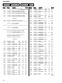
CDX-M800
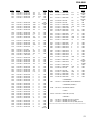
• IC2 M30833FJGP-066 (DISPLAY SYSTEM CONTROL) (DISPLAY Board)
Pin No. Pin Name I/O Pin Description
1 SYS RST I Main chip enable input
2NCINot used. (Open)
3 FL DATA3 O FL serial data output
4NCONot used. (Open)
5 FL CLK IN I FL serial clock input
6 BYTE I L fixed terminal
7 CNVSS I Flash write-in signal input
8NCONot used. (Open)
9NCONot used. (Open)
10 RESET I CPU reset signal input
11 XOUT O Main clock signal output (30MHz)
12 VSS — Ground
13 XIN I Main clock signal input (30MHz)
14 VCC — Power supply pin (+5V)
15 NMI I Non maskable interrupt signal input
16 NC O Not used. (Open)
17 NC O Connecting to pin 20.
18 NC O Not used. (Open)
19 NC O Not used. (Open)
20 NC O Connecting to pin 17.
21 LAT O FL data LAT output
22 BK O FL BK output
23 GCP2 O FL GCP2 outpit
24 NC O Not used. (Open)
25 GCP1 O FL GCP1 output
26 NC O Not used. (Open)
27 GCP4 O FL GCP4 output
28 GCP3 O FL GCP3 output
29 SYS SO O Main BUS data output
30 SYS SI I CPU BUS data input
31 SYS CLK O Main BUS clock input
32 NC O Not used. (Open)
33 FL DAT1 O FL serial data output
34 NC O Not used. (Open)
35 FL CLK O FL serial clock output
36 LCD CE O LCD driver chip enble output
37 LCD INH O LCD driver inhibit output
38 NC O Not used. (Open)
39 HOLD I Flash write-in signal input
40 – 43 NC O Not used. (Open)
44 WRI/WR I Flash write-in signal input
45 – 59 NC O Not used. (Open)
60 VCC O Power supply pin (+5V)
61 NC O Not used. (Open)
62 VSS O Ground
63 – 93 NC O Not used. (Open)
94 AVSS — Ground
95 NC O Not used. (Open)
96 VREF — Power supply pin (+5V)
97 AVCC — Power supply pin (+5V)
98 RXD1 — Not used. (Open)
99 FL DATA2 O FL serial data output
100 FL CLK IN I FL serial clock input
Page is loading ...
Page is loading ...
Page is loading ...
Page is loading ...
Page is loading ...
Page is loading ...
Page is loading ...
Page is loading ...
Page is loading ...
Page is loading ...
Page is loading ...
Page is loading ...
Page is loading ...
Page is loading ...
Page is loading ...
Page is loading ...
Page is loading ...
Page is loading ...
Page is loading ...
Page is loading ...
Page is loading ...
Page is loading ...
Page is loading ...
Page is loading ...
Page is loading ...
Page is loading ...
Page is loading ...
Page is loading ...
Page is loading ...
Page is loading ...
Page is loading ...
Page is loading ...
Page is loading ...
Page is loading ...
-
 1
1
-
 2
2
-
 3
3
-
 4
4
-
 5
5
-
 6
6
-
 7
7
-
 8
8
-
 9
9
-
 10
10
-
 11
11
-
 12
12
-
 13
13
-
 14
14
-
 15
15
-
 16
16
-
 17
17
-
 18
18
-
 19
19
-
 20
20
-
 21
21
-
 22
22
-
 23
23
-
 24
24
-
 25
25
-
 26
26
-
 27
27
-
 28
28
-
 29
29
-
 30
30
-
 31
31
-
 32
32
-
 33
33
-
 34
34
-
 35
35
-
 36
36
-
 37
37
-
 38
38
-
 39
39
-
 40
40
-
 41
41
-
 42
42
-
 43
43
-
 44
44
-
 45
45
-
 46
46
-
 47
47
-
 48
48
-
 49
49
-
 50
50
-
 51
51
-
 52
52
-
 53
53
-
 54
54


Sony Xplod CDX-M800 User manual
- Category
- Car video systems
- Type
- User manual
- This manual is also suitable for
Ask a question and I''ll find the answer in the document
Finding information in a document is now easier with AI
Related papers
-
Sony CDX-GT50W User manual
-
Sony CDX-M800 Owner's manual
-
-
Sony CDX-GT360MP Operating Instructions Manual
-
Sony CDX-F7700 Installation guide
-
-
Sony CDX-M800 Installation guide
-
Sony CDX-MP70 User manual
-
Sony CDX-M800 Installation guide
-