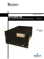
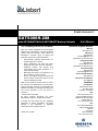
Emerson LIEBERT GXT5000R-208 is a high-quality uninterruptible power supply (UPS) device that provides reliable backup power in the event of a power outage, ensuring that your critical equipment remains protected and operational. With a power capacity of 5000VA/3750W and a voltage of 208V, it is suitable for powering small to medium-sized devices like servers, workstations, and networking equipment. The GXT5000R-208 utilizes advanced technology to deliver clean and stable power, ensuring the smooth operation of your equipment and preventing data loss or damage.
Emerson LIEBERT GXT5000R-208 is a high-quality uninterruptible power supply (UPS) device that provides reliable backup power in the event of a power outage, ensuring that your critical equipment remains protected and operational. With a power capacity of 5000VA/3750W and a voltage of 208V, it is suitable for powering small to medium-sized devices like servers, workstations, and networking equipment. The GXT5000R-208 utilizes advanced technology to deliver clean and stable power, ensuring the smooth operation of your equipment and preventing data loss or damage.


-
 1
1
-
 2
2
-
 3
3
-
 4
4
-
 5
5
-
 6
6
-
 7
7
-
 8
8
-
 9
9
-
 10
10
-
 11
11
-
 12
12
-
 13
13
-
 14
14
-
 15
15
-
 16
16
-
 17
17
-
 18
18
-
 19
19
-
 20
20
-
 21
21
-
 22
22
-
 23
23
-
 24
24
-
 25
25
-
 26
26
-
 27
27
-
 28
28
-
 29
29
-
 30
30
-
 31
31
-
 32
32


Emerson LIEBERT GXT5000R-208 User manual
- Type
- User manual
- This manual is also suitable for
Emerson LIEBERT GXT5000R-208 is a high-quality uninterruptible power supply (UPS) device that provides reliable backup power in the event of a power outage, ensuring that your critical equipment remains protected and operational. With a power capacity of 5000VA/3750W and a voltage of 208V, it is suitable for powering small to medium-sized devices like servers, workstations, and networking equipment. The GXT5000R-208 utilizes advanced technology to deliver clean and stable power, ensuring the smooth operation of your equipment and preventing data loss or damage.
Ask a question and I''ll find the answer in the document
Finding information in a document is now easier with AI
Related papers
-
Emerson 115-50/60HZ User manual
-
-
Emerson GXT3 User manual
-
Liebert Liebert GXT2U 208V User manual
-
-
Liebert GXT3-5000RT208 User manual
-
-
-
-
Other documents
-
-
-
-
-
-
-
-
Avocent GXT2-6000RT208 User manual
-
-