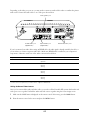
Epson Ensemble HD 8500 User manual
- Category
- Data projectors
- Type
- User manual

Installation Guide

2
Copyright Notice
All rights reserved. No part of this publication may be reproduced, stored in a retrieval system, or transmitted in any form
or by any means, electronic, mechanical, photocopying, recording, or otherwise, without the prior written permission of
Seiko Epson Corporation.
The information contained herein is designed only for use with this Epson product. Epson is not responsible for any use
of this information as applied to other equipment.
Neither Seiko Epson Corporation nor its affiliates shall be liable to the purchaser of this product or third parties for
damages, losses, costs, or expenses incurred by purchaser or third parties as a result of: accident, misuse, or abuse of this
product or unauthorized modifications, repairs, or alterations to this product, or (excluding the U.S.) failure to strictly
comply with Seiko Epson Corporation’s operating and maintenance instructions.
Trademarks
Epson is a registered trademark and Epson Exceed Your Vision is a logomark of Seiko Epson Corporation.
PowerLite and PrivateLine are registered trademarks, Ensemble HD is a trademark, and Epson Store is a service mark, of
Epson America, Inc.
The DVD Video logo is a trademark of DVD Format/Logo Licensing Corporation.
Manufactured under license from Dolby Laboratories. “Dolby”, “Pro Logic”, and the double-D symbol are trademarks of
Dolby Laboratories.
“DTS” and “DTS Digital Surround” are registered trademarks of Digital Theater Systems, Inc.
General Notice: Other product names used herein are for identification purposes only and may be trademarks of their
respective owners. Epson disclaims any and all rights in those marks.
This information is subject to change without notice.
© 2008 Epson America, Inc. 4/08 CPD-24458

3
Contents
Introduction . . . . . . . . . . . . . . . . . . . . . . . . . . . . . . . . . . . . . . . . . . . . . . . . . . . . . . . . . . . . . . . . . . . . . . 5
Important Safety Instructions. . . . . . . . . . . . . . . . . . . . . . . . . . . . . . . . . . . . . . . . . . . . . . . . . . . . . 6
Parts List . . . . . . . . . . . . . . . . . . . . . . . . . . . . . . . . . . . . . . . . . . . . . . . . . . . . . . . . . . . . . . . . . . . . 10
Included Cables . . . . . . . . . . . . . . . . . . . . . . . . . . . . . . . . . . . . . . . . . . . . . . . . . . . . . . . . . . . . . . . 11
Additional Accessories . . . . . . . . . . . . . . . . . . . . . . . . . . . . . . . . . . . . . . . . . . . . . . . . . . . . . . . . . . 11
Where To Get Help . . . . . . . . . . . . . . . . . . . . . . . . . . . . . . . . . . . . . . . . . . . . . . . . . . . . . . . . . . . . 12
Planning the Installation. . . . . . . . . . . . . . . . . . . . . . . . . . . . . . . . . . . . . . . . . . . . . . . . . . . . . . . . . . . 13
Required Tools. . . . . . . . . . . . . . . . . . . . . . . . . . . . . . . . . . . . . . . . . . . . . . . . . . . . . . . . . . . . . . . . 14
Laying Out the Home Theater . . . . . . . . . . . . . . . . . . . . . . . . . . . . . . . . . . . . . . . . . . . . . . . . . . . . 14
Locating the Screen . . . . . . . . . . . . . . . . . . . . . . . . . . . . . . . . . . . . . . . . . . . . . . . . . . . . . . . . . . . . 15
Locating the Projector . . . . . . . . . . . . . . . . . . . . . . . . . . . . . . . . . . . . . . . . . . . . . . . . . . . . . . . . . . 16
Locating Other Components . . . . . . . . . . . . . . . . . . . . . . . . . . . . . . . . . . . . . . . . . . . . . . . . . . . . . 16
Routing the Cables. . . . . . . . . . . . . . . . . . . . . . . . . . . . . . . . . . . . . . . . . . . . . . . . . . . . . . . . . . . . . 16
Making Optional Connections. . . . . . . . . . . . . . . . . . . . . . . . . . . . . . . . . . . . . . . . . . . . . . . . . . . . 17
Cable Connections . . . . . . . . . . . . . . . . . . . . . . . . . . . . . . . . . . . . . . . . . . . . . . . . . . . . . . . . . . . . . 18
Installing the Screen . . . . . . . . . . . . . . . . . . . . . . . . . . . . . . . . . . . . . . . . . . . . . . . . . . . . . . . . . . . . . . 19
Unpack the Screen and Speaker Grilles. . . . . . . . . . . . . . . . . . . . . . . . . . . . . . . . . . . . . . . . . . . . . . 19
Attach the Speaker Grilles to the Screen . . . . . . . . . . . . . . . . . . . . . . . . . . . . . . . . . . . . . . . . . . . . . 20
Attach the Mounting Assembly to the Wall (Option 1) . . . . . . . . . . . . . . . . . . . . . . . . . . . . . . . . . 21
Attach the Mounting Assembly to the Ceiling (Option 2) . . . . . . . . . . . . . . . . . . . . . . . . . . . . . . . 24
Connect the Cables to the Screen . . . . . . . . . . . . . . . . . . . . . . . . . . . . . . . . . . . . . . . . . . . . . . . . . . 26
Lift the Screen onto the Mounting Brackets . . . . . . . . . . . . . . . . . . . . . . . . . . . . . . . . . . . . . . . . . . 29
Installing the Projector . . . . . . . . . . . . . . . . . . . . . . . . . . . . . . . . . . . . . . . . . . . . . . . . . . . . . . . . . . . . 31
Position the Ceiling Mount . . . . . . . . . . . . . . . . . . . . . . . . . . . . . . . . . . . . . . . . . . . . . . . . . . . . . . 32
Attach the Extension Arm (Optional). . . . . . . . . . . . . . . . . . . . . . . . . . . . . . . . . . . . . . . . . . . . . . . 35
Install the Ceiling Mount . . . . . . . . . . . . . . . . . . . . . . . . . . . . . . . . . . . . . . . . . . . . . . . . . . . . . . . . 37
Mount the Projector. . . . . . . . . . . . . . . . . . . . . . . . . . . . . . . . . . . . . . . . . . . . . . . . . . . . . . . . . . . . 38
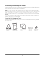
Connecting and Routing the Cables . . . . . . . . . . . . . . . . . . . . . . . . . . . . . . . . . . . . . . . . . . . . . . . . 43
Unpack the Wire Management Tracks . . . . . . . . . . . . . . . . . . . . . . . . . . . . . . . . . . . . . . . . . . . . . . 43
Install the Tracks and Connector Pieces . . . . . . . . . . . . . . . . . . . . . . . . . . . . . . . . . . . . . . . . . . . . . 44
Connect the Cables to the Projector . . . . . . . . . . . . . . . . . . . . . . . . . . . . . . . . . . . . . . . . . . . . . . . . 45
Connect the Cables to the Subwoofer and AV Controller. . . . . . . . . . . . . . . . . . . . . . . . . . . . . . . . 46
Assembling the Subwoofer Stand. . . . . . . . . . . . . . . . . . . . . . . . . . . . . . . . . . . . . . . . . . . . . . . . . . 49
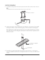
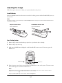
Adjusting the Image . . . . . . . . . . . . . . . . . . . . . . . . . . . . . . . . . . . . . . . . . . . . . . . . . . . . . . . . . . . . . . 51
Insert Batteries . . . . . . . . . . . . . . . . . . . . . . . . . . . . . . . . . . . . . . . . . . . . . . . . . . . . . . . . . . . . . . . . 51
Turn On the System. . . . . . . . . . . . . . . . . . . . . . . . . . . . . . . . . . . . . . . . . . . . . . . . . . . . . . . . . . . . 51
Adjust the Screen Position . . . . . . . . . . . . . . . . . . . . . . . . . . . . . . . . . . . . . . . . . . . . . . . . . . . . . . . 52
Position the Image . . . . . . . . . . . . . . . . . . . . . . . . . . . . . . . . . . . . . . . . . . . . . . . . . . . . . . . . . . . . . 53
Adjusting the Projector Settings . . . . . . . . . . . . . . . . . . . . . . . . . . . . . . . . . . . . . . . . . . . . . . . . . . . 56
Set the Color Mode . . . . . . . . . . . . . . . . . . . . . . . . . . . . . . . . . . . . . . . . . . . . . . . . . . . . . . . . . . . . 57

4
Adjusting the Sound . . . . . . . . . . . . . . . . . . . . . . . . . . . . . . . . . . . . . . . . . . . . . . . . . . . . . . . . . . . . . . 58
Set the Boundary Control Switch . . . . . . . . . . . . . . . . . . . . . . . . . . . . . . . . . . . . . . . . . . . . . . . . . . 58
Set the Speaker Distance. . . . . . . . . . . . . . . . . . . . . . . . . . . . . . . . . . . . . . . . . . . . . . . . . . . . . . . . . 59
Equalize the Speaker Output . . . . . . . . . . . . . . . . . . . . . . . . . . . . . . . . . . . . . . . . . . . . . . . . . . . . . 60
Adjust the Subwoofer Output . . . . . . . . . . . . . . . . . . . . . . . . . . . . . . . . . . . . . . . . . . . . . . . . . . . . 60
After Completing the Installation . . . . . . . . . . . . . . . . . . . . . . . . . . . . . . . . . . . . . . . . . . . . . . . . . . . 62
Using Additional Components . . . . . . . . . . . . . . . . . . . . . . . . . . . . . . . . . . . . . . . . . . . . . . . . . . . . . 63
Connecting External Video Devices . . . . . . . . . . . . . . . . . . . . . . . . . . . . . . . . . . . . . . . . . . . . . . . . 63
Connecting Another Subwoofer . . . . . . . . . . . . . . . . . . . . . . . . . . . . . . . . . . . . . . . . . . . . . . . . . . . 68
Connecting an Antenna . . . . . . . . . . . . . . . . . . . . . . . . . . . . . . . . . . . . . . . . . . . . . . . . . . . . . . . . . 69
Using a Third-party Universal Remote Control . . . . . . . . . . . . . . . . . . . . . . . . . . . . . . . . . . . . . . . 71

5
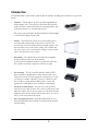
Introduction
The Ensemble HD home cinema system by Epson includes everything that’s needed to set up a home
theater.
•
Projector – The PowerLite projector provides high-definition,
theater-quality video. The projector is housed in the integrated
speaker enclosure, which contains the rear surround speakers, part
of the home theater’s 5.1-channel audio system.
The system comes with either the PowerLite Home Cinema 1080
or the PowerLite Home Cinema 720.
•
Screen – The widescreen-format (16:9) motorized projection
screen descends automatically at the touch of a button. The
screen incorporates front-channel (left/center/right) speakers. You
can mount the screen on the wall or ceiling. If you wall-mount
the screen, there’s even room behind it to hang a work of art that
can be seen when the screen is raised.
•
Subwoofer – The 10-inch subwoofer with built-in amplifier
provides rich bass and powers all the speakers
in the system. The included stand lets you place the subwoofer,
AV controller, and other components neatly in one place.
•
AV controller – The AV controller includes a built-in DVD
player and delivers high-definition video and surround sound
output. You can also connect existing AV components to it, such
as a cable box, satellite or digital TV receiver, or DVR. Use the
AV controller to switch between different video sources and
optimize the sound quality for the installation environment.
•
Universal remote control – Lets you turn on the projector,
lower the screen, switch between video sources, watch movies, and
adjust the volume. You can also program it to work with other AV
equipment. Just aim the remote control at the screen—a sensor at
the top of the screen detects the signal.
•
Wire management tracks – Specially molded tracks let you
discreetly hide all the cables instead of routing them through the
wall and ceiling.
TM
®
®

6
Important Safety Instructions
CAUTION: To reduce the risk of electric shock, do not remove the cover (or back). No user serviceable parts
inside. Refer servicing to qualified personnel.
CAUTION: These servicing instructions are for use by qualified service personnel only. To reduce t h e r isk of
electric shock, do not perform any servicing other than that contained in the operating instructions unless you
are qualified to do so.
WARNING: To reduce the risk of fire or electric shock, do not expose this apparatus to rain or moisture.
The lightning flash with arrowhead, within an equilateral triangle, is intended to alert the user to
the presence of uninsulated “dangerous voltage” within the product’s enclosure that may be of
sufficient magnitude to constitute a risk of electrical shock to persons.
The exclamation point within an equilateral triangle is intended to alert the user to the presence
of important operating maintenance (servicing) instructions in the literature accompanying the
appliance.
1. Read these instructions.
2. Keep these instructions.
3. Heed all warnings.
4. Follow all instructions.
5. Do not use this apparatus near water.
6. Clean only with dry cloth.
7. Do not block any ventilation openings. Install in accordance with the manufacturer’s instructions.
8. Do not install near any heat sources such as radiators, heat registers, stoves, or other apparatus (including
amplifiers) that produce heat.
9. Do not defeat the safety purpose of the polarized or grounding-type plug. A polarized plug has two blades
with one wider than the other. A grounding type plug has two blades and a third grounding prong. The
wide blade or the third prong is provided for your safety. If the provided plug does not fit into your outlet,
consult an electrician for replacement of the obsolete outlet.
10. Protect the power cord from being walked on or pinched particularly at plugs, convenience receptacles,
and the point where they exit from the apparatus.
11. Only use attachments/accessories specified by the manufacturer.
12. Unplug this apparatus during lightning storms or when unused for long periods of time.

7
13. Refer all servicing to qualified service personnel. Servicing is required when the apparatus has been
damaged in any way, such as power-supply cord or plug is damaged, liquid has been spilled or objects have
fallen into the apparatus, the apparatus has been exposed to rain or moisture, does not operate normally, or
has been dropped.
Additional Safety Instructions
• Safety measures must be practiced at all times during the installation of the home theater system. Proper
installation procedures, as outlined in these instructions, must be adhered to. Failure to do so could result
in serious personal injury or death.
• The home theater system should be installed by a professional audio/video installer or other qualified
professional. Epson cannot provide advice concerning construction practices or building codes in your
area.
• Prior to installing the home theater system, read the installation instructions completely. Keep these
instructions in an easily accessible place for future reference.
• Do not attempt to install this system if you have any doubts as to its proper assembly and installation.
• Use proper equipment to prevent personal injury or property damage, such as a ladder for reaching high
places or a stud finder to locate the center of studs.
• The included mounting hardware is intended for use with wooden studs/joists or solid concrete
construction. The hardware is not intended to secure any part of the system to metal studs, wallboard or
plasterboard, or cinder block wall construction.
• Do not attempt to use hollow-wall anchors, screws, or similar mounting hardware to mount the projector
or screen to wallboard or plasterboard. The projector and screen cannot be safely mounted like that. You
must mount the projector and screen to wooden studs/joists or to a solid concrete surface, as outlined in
these instructions.
• When installing the mounting hardware in concrete, verify that the concrete is at least the same depth as
the anchors, and that the anchors will not rest against a layer of plasterboard or other material. Concrete
must meet ASTM C-90 specifications and be 2000 psi density minimum. Lighter-density concrete may
not hold the anchors.
• The wall or ceiling structure on which the screen is mounted must be capable of safely supporting the
weight of the screen (approximately 100 pounds). Likewise, the ceiling structure must be capable of safely
supporting the weight of the projector assembly (approximately 50 pounds). If the structures cannot
support these weights, they must be reinforced.
• When mounting the equipment on a wall or ceiling that contains studs or joists, the exact center of the
studs or joists must be confirmed prior to installation.
• Do not install the projector or screen where it may be subject to impact.
• Do not install the projector or screen in direct sunlight or near a heater vent, fireplace, or other source of
heat.
• Two persons are required to lift the screen onto its mounting brackets. It is recommended that a second
person should also assist in performing other parts of the installation, such as mounting the projector and

8
routing wires. Personal injury and/or damage to the equipment could result from dropping or mishandling
it.
• Make sure the screen is completely closed before placing it on or lifting it off the wall or ceiling mount.
• Do not route the included power cables through the wall or ceiling. They are not rated for this purpose.
Deliberate mis-installation could result in fire or other safety hazards. Either route the power cables
through the included wire management tracks, or plug them directly into nearby outlets.
• Some of the components included with this system may be packaged in plastic bags. Keep plastic bags
away from small children to avoid any risk of suffocation.
• This product should be operated only from the type of power source indicated on the marking label.
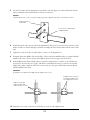
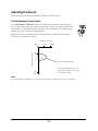
• If an outside antenna or cable system is connected to the product, be sure the antenna or cable system is
grounded so as to provide some protection against voltage surges and built-up static charges. Article 810 of
the National Electrical Code, ANSI/NFPA 70, provides information with regard to proper grounding of
the mast and supporting structure, grounding of the lead-in wire to an antenna discharge unit, size of
grounding conductors, location of antenna-discharge unit, connection to grounding electrodes, and
requirements for the grounding electrode. See the drawing below.
• An outside antenna system should not be located in the vicinity of overhead power lines or other electric
light or power circuits, or where it can fall into such power lines or circuits. When installing an outside
antenna system, extreme care should be taken to keep from touching such power lines or circuits as contact
with them might be fatal.
• Do not place the components of this system near sources of heat or in direct sunlight.
• Make sure nothing blocks the ventilation openings on any of the components. Allow for sufficient heat
dispersion when components are installed on a rack. Do not block or cover the heatsink on the back of the
subwoofer.
• Where the mains plug is used as the disconnect device, the disconnect device shall remain readily operable.
• When unplugging the power cord of any system component, handle it carefully. Hold the plug when
unplugging the cord.
• This product should be operated only from the type of power source indicated on the marking label. If you
are not sure of the type of power supplied in your home, consult your product dealer or local power
company.
ANTENNA
LEAD IN
WIRE
GROUND
CLAMP
ELECTRIC
SERVICE
EQUIPMENT
ANTENNA
DISCHARGE UNIT
(NEC SECTION 810-20)
GROUNDING CONDUCTORS
(NEC SECTION 810-21)
POWER SERVICE GROUNDING
ELECTRODE SYSTEM
(NEC ART 250, PART H)
GROUND CLAMPS

9
• Do not overload wall outlets, extension cords, or integral convenience receptacles as this can result in a risk
of fire or electric shock.
• Keep the system components free from moisture, water, and dust.
• Do not let insecticides, benzene, or thinner come in contact with any components of the system.
• Never push objects of any kind through openings in the system components as they may touch dangerous
voltage points or short-out parts that could result in a fire or electric shock. Never spill liquid of any kind
on the product.
• Except as specifically explained in these instructions, do not attempt to service this product yourself. Refer
all servicing to qualified service personnel.
• Never disassemble or modify the product in any way. Dangerous electrical voltages inside the components
can severely injure you.
• When replacement parts are required, be sure the service technician has used replacement parts specified by
the manufacturer or have the same characteristics as the original part. Unauthorized substitutions may
result in fire, electric shock, or other hazards.
• When closing the screen, be careful not to pinch your fingers where the screen closes against the case.
• Do not touch the white part of the screen with your hands. Oil from your skin could damage it.
• Never look into the projector lens when the lamp is turned on. The bright light can damage your eyes.
Never let children look into the lens when it is on.
• Don’t use the projector outside of the required temperature range of 41 to 95 °F (5 to 35 °C). Doing so
may cause an unstable display and could lead to projector damage.
• The lamp(s) in this product contain mercury. Please consult your state and local regulations regarding
disposal or recycling. Do not put in the trash.
• Allow the projector lamp to cool for one hour before replacing it.
WARNING: Handling the cord on this product or cords associated with accessories sold with this product, will
expose you to lead, a chemical known to the State of California to cause birth defects or other reproductive
harm. Wash hands after handling. (This notice is provided in accordance with Proposition 65 in Cal. Health &
Safety Code § 25249.5 and following.)

10
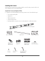
Parts List
Before starting, make sure you have all the boxes listed below.
Tip
Leave all the items in their containers until the instructions tell you to remove them. That way, you can easily find the parts
you’ll need at different points during the installation.
Box #1
• Projector (PowerLite Home Cinema 1080 or PowerLite Home Cinema 720)
• Projector ceiling mount
• AV controller with built-in DVD player (includes remote control)
Box #2
• Projector enclosure and rear surround speakers
Box #3
• AV Cables (see “Included Cables” on page 11 for details) and HDMI repeater
Box #4
• Screen and screen mounting hardware
• Wire management tracks (8 feet long)
• Wire management connector pieces, seam covers, and drywall screws
Box #5
• Subwoofer
•AC power cables
Box #6
• Subwoofer stand
Box #7
• Speaker grilles for screen
Note
The included hardware is designed to let you mount the screen and projector on surfaces containing wooden studs/joists
or on solid concrete walls and ceilings. You may need additional hardware if your setup varies, or to mount the wire
management track on a concrete surface.

11
Included Cables
All required cables are included, as listed below:
Refer to the connection diagram on page 18 for an overview of how all the cables are connected.
Note
An extra-long cable set is also available. See “Additional Accessories” below.
Additional Accessories
You can enhance the home theater with these accessories:
• Rear surround speaker kit lets you move the rear speakers from the projector to an alternative location.
• Extra-long cable set for connecting the projector to the screen. Suitable for installations where the audio
and video cables are routed through the wall and ceiling, or where you want to place the projector at a
greater distance from the screen.
You can purchase these accessories from an Epson authorized reseller. To find the nearest reseller, call
800-GO-EPSON (800-463-7766). To purchase online, visit www.EnsembleHD.com (U.S. sales only).
Cable connection Cable name Length
From power outlet to subwoofer Main power cord 6 feet (1.8 m)
From AV equipment to screen AC power cable *
Speaker cable *
HDMI video cable **
Control cable with mini-jack connector **
* Connects from subwoofer to screen.
** Connects from AV controller to screen.
33 feet (10 m)
From screen to projector AC power cable
Speaker cable
HDMI video cable
Control cable with serial connector
23 feet (7 m)
From subwoofer to AV controller AV data cable 9 feet (2.7 m)

12
Where To Get Help
Epson provides the following technical support services for your home theater system.
Note
Epson strongly recommends that the home theater system be installed by a professional audio/video installer or other
qualified professional. Epson cannot provide advice concerning construction practices or building codes in your area.
Internet Support
Visit Epson’s support website at epson.com/support and select your product for solutions to common
problems. You can download documentation, get FAQs and troubleshooting advice, or e-mail Epson with your
questions.
Speak to a Support Representative
To use the Epson PrivateLine Support service, call (800) 637-7661 and enter the PIN on the Epson
PrivateLine Support card that came with your projector. This is the fastest way of speaking to a live
representative, and it’s free. This service is available 6
AM to 6 PM, Pacific Time, Monday through Friday, for
the duration of your warranty period.
You may also speak with a support specialist by dialing (562) 276-4394, 6
AM to 6 PM, Pacific Time, Monday
through Friday.
Days and hours of support are subject to change without notice. Toll or long distance charges may apply.
Before you call, please have the following information ready:
■ Product name (Ensemble HD home cinema system)
■ Product serial number (located on the back of the weighted bar on the bottom of the screen, on the right
side of the screen as viewed from the front)
■ Description of the problem
Purchase Supplies and Accessories
You can purchase genuine Epson supplies and accessories from an Epson authorized reseller. To find the
nearest reseller, call 800-GO-EPSON (800-463-7766). To purchase online, visit www.epsonstore.com (U.S.
sales) or www.epson.ca (Canadian sales).
®

13
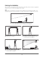
Planning the Installation
Here are the basic steps required to install the home theater system. Allow at least 4 to 6 hours to complete the
installation. Be sure to read the following pages before starting.
Note
Epson strongly recommends that the home theater system be installed by a professional audio/video installer or other
qualified professional. Epson cannot provide advice concerning construction practices or building codes in your area.
Screen image
1
Plan the screen location and room layout. The seating area should
be in the middle and the projector toward the rear. See page 14.
3
Install the ceiling mount and projector. Use a
stud finder to locate wooden joists on which to
mount the projector. See page 31.
4
Connect the equipment and route cables.
Use the included wire management tracks to
route the cables. See page 43.
5
Adjust the image and sound. See page 51.
2
Hang the screen. Two persons are required to
lift the screen. See page 19.

14
Required Tools
The Ensemble HD home theater system should be installed by a professional audio/video installer or other
qualified professional. To install the system, the installer will need these tools:
• Phillips head screwdrivers
• Power drill and drill bits
• Tool for cutting plastic wire management tracks, such as a hacksaw
• Tape measure
•Level
• Stud finder (“edge to edge” stud finder is recommended)
• Sound-level meter, such as model 33-2055 available from Radio Shack
• Ladder
Warning
Do not route the included power cables through the wall or ceiling. They are not rated for this purpose. Deliberate
mis-installation could result in fire or other safety hazards.
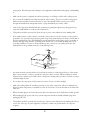
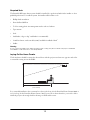
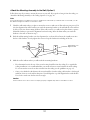
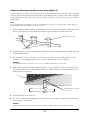
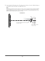
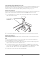
Laying Out the Home Theater
The home theater should be arranged as shown below, with the projector and screen at opposite ends of the
room and the seating area in the middle.
For a successful installation, the room must be at least 13 feet long (for the PowerLite Home Cinema 1080) or
13.5 feet long (for the PowerLite Home Cinema 720). If your room is shorter than this, you won’t be able to
install the projector far enough back for the image to fill the whole screen.
®
12 to 16 feet
(3.7 to 4.9 m)

15
Keep the following in mind:
• Your seating area should allow for a comfortable viewing distance to the screen. The seats should be
arranged to allow viewing from approximately 12 to 16 feet away (3.7 to 4.9 m).
• For best surround-sound performance, the projector (with its rear surround speakers) should be placed as
far behind the seating area as possible.
• If the projector is close to the rear wall, you must leave enough space to rotate the projector when
mounting it and to be able to connect cables to its ports in back.
Ideally, your room should be at least 16 feet (4.9 m) long to accommodate these needs and to achieve the
optimal home theater experience—but rooms shorter than that can still provide excellent results.
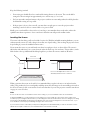
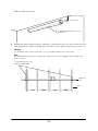
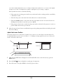
Locating the Screen
The screen is the first thing you’ll need to find a location for. With the included mounting hardware, you can
either mount the screen on a wall or hang it from a flat (not sloped) ceiling. (You can hang the projector from a
sloped ceiling if you use the included extension arm.)
If you mount the screen on your wall, make sure there’s enough space for it, as shown below. The screen is
101 inches wide and factory-set to come down 61 inches from the top of its enclosure. This provides a 3-inch
black border at the top. Additional black drop length lets you lower the screen as much as 70 inches.
When you mount the screen on the wall, it’s recommended that you place it from 2 to 22 inches from the
ceiling. This produces the best sound quality and helps ensure that the image can be successfully positioned on
the screen. You may be able to mount the screen lower than that if you use the projector extension arm shown
on page 31 (see note below).
Note
Do not mount the screen closer than 2 inches from the ceiling, or you won’t be able to lift it onto the brackets.
In a typical installation, you can position the screen with the top of its housing up to 22 inches from the ceiling. If you
mount the projector using the extension arm, you can hang the screen as low as 29 inches from the ceiling. If your ceiling
is sloped, the vertical distance between the lens and the top of the screen housing must not exceed 15 inches, or you
won’t be able to lower the projected image enough to fit it on the screen.
If you mount the screen on the wall, you may wish to hang a work of art behind it that you can see when the screen is
raised. There is a space of about 2 1/2 inches behind the screen when it’s lowered.
70 inches
101 inches
61 inches
Note: You can adjust the screen so it comes
down anywhere from 61 to 70 inches.

16
Locating the Projector
Once you know where the screen will go, you can determine the location of the projector. For the best sound
quality from the rear surround speakers, you should mount the projector as far behind the seating area as
possible. In a typical installation with the screen mounted near the ceiling, you can place the projector mount
up to about 19 feet (5.8 m) from the screen (limited by the length of the cables). However, because installations
vary, you should confirm that the cables will in fact reach the location you choose for the projector (see step 1
on page 32).
When choosing a location for the projector, it’s important to align it with the middle of the screen as much as
possible, instead of offsetting it to one side (see step 2 on page 33). Your installation will look best this way, and
it also helps ensure that the image can be successfully positioned on the screen.
Locating Other Components
The subwoofer can be placed anywhere in the front of the room. Its exact placement does not affect sound
quality. Since the subwoofer powers all other components in the system, you should place it within 6 feet
(1.8 m) of a power outlet. You should also place it within 9 feet (2.7 m) of cabling distance from the
AV controller and 33 feet (10 m) of cabling distance from the screen (see “Routing the Cables” in the next
section).
An optional stand is included in which the subwoofer and other components can be placed. If you choose to
use it, you can place the AV controller on it, along with your existing components such as a cable box or digital
TV receiver.
Because there does not have to be a clear line-of-sight from the remote control to the AV controller in order to
use it, it is possible to keep the AV controller inside a closed cabinet, if desired. Then when you aim the remote
control at the screen, a sensor in the screen detects the remote control signal and relays it to the AV controller.
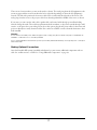
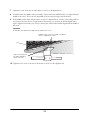
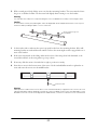
Routing the Cables
See the diagram on page 18 for an overview of how all the Ensemble HD components are connected.
Once you’ve connected the cables, you can use the included wire management tracks to route the cables neatly
over your wall and ceiling. The tracks can be cut to length as needed, and after they’re installed you can paint
them to blend in with the room, if necessary.
Track from screen to projector
Track from AV equipment
to screen

17
There are two locations where you can use the tracks, as shown. The track going from the AV equipment to the
screen can approach the screen from either the left or right side, depending on where the AV equipment is
located. (The left side is preferred so that excess cable can be stored inside the right side of the screen.) The
track going from the screen to the projector looks best when aligned with the middle of the screen, as shown.
If you want, you can route the video cable, speaker cable, and control cable through your wall and ceiling
instead of using the tracks. These cables are plenum-rated (fire retardant), so they can be routed through a wall,
an attic, or the space above your ceiling. If you choose this option, plug the AC power cables for the screen and
projector directly into nearby electrical outlets. If no outlets are available, contact a licensed electrician to have
them installed.
Warning
Do not route the included power cables through the wall or ceiling. They are not rated for this purpose. Deliberate mis-
installation could result in fire or other safety hazards.
It is recommended that the Ensemble HD system be powered by a dedicated 20-amp circuit. Typical power consumption
is about 800 watts.
Making Optional Connections
Once the Ensemble HD system is installed and adjusted, you can connect additional components such as a
cable box, satellite receiver, or DVR. See “Using Additional Components” on page 63.

18
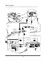
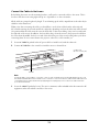
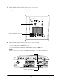
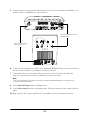
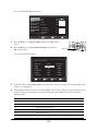
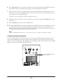
Cable Connections
Refer to the diagram below for an overview of how all the Ensemble HD components are connected:
47
61 82
FREQ LEVEL
PWR ON MODE
SUB OUT
BASS CONTOUR CONTROL
98
99
Rear surround
speakers
L/C/R speaker
connectors
AV d a ta c a bl e
Control cable
HDMI cable
HDMI repeater and
power supply
Control cable
HDMI
cable
110 VAC power cable
Main power
cord
110 VAC power cables
Speaker
cable
Speaker
cable
Projector
Motorized
screen
Subwoofer
AV Controller

19
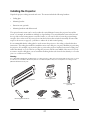
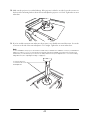
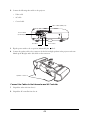
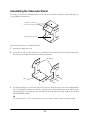
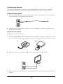
Installing the Screen
Follow these steps to attach the screen’s mounting assembly to your wall or ceiling, connect the cables to the
screen, and lift the screen onto the mounting brackets.
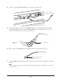
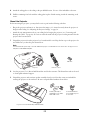
Unpack the Screen and Speaker Grilles
1 Unpack the screen and related hardware from the long container (box #4). You will need these parts:
• Screen (without speaker grilles)
•Alignment bar
• Wall-mounting brackets
• Ceiling-mounting brackets
• Mounting hardware (to mount the screen to wooden studs/joists or a solid concrete surface)
Ceiling-mounting brackets
Screen (without speaker grilles)
Wood screws
(8 pieces)
Alignment bar
TOGGLER
®
-brand
wall anchors
(2 pieces in bag)
Wall-mounting brackets
Concrete anchors
and anchor bolts
(8 pieces each)
Mounting bracket
face screws (4 pieces)
Set screw
for screen
Allen wrench for
set screw
Allen wrench for black
drop adjustment
(keep for customer)

20
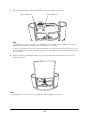
Note
The box also contains the wire management tracks and related pieces shown below. It is advisable to keep these
parts together until they’re needed on page 43.
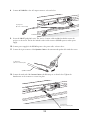
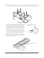
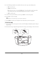
2 Unpack the speaker grilles from box #7. Note that two screws are packed with each grille. You will use
them to attach the grille to the screen, as described in the next section.
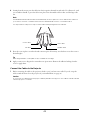
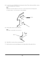
Attach the Speaker Grilles to the Screen
1 Remove and discard the plastic covers that protect the speakers during shipping.
2 Attach the speaker grilles. Hook each grille into the lip underneath the screen housing (where the screen
itself comes out). Then attach the grille on top with the two screws that came with it.
Caution
Be careful not to damage the grilles when handling them. Do not hold the screen by the grilles, which are fragile and
can be easily dented. Lift the screen only from the bottom and by holding the plastic covers on each end.
Wall-to-ceiling
transition (2 sets)
Corner connector
(3 sets)
Seam cover
(20 pieces)
8-foot-long tracks
(6 pieces)
Drywall screws
(100 pieces)
Speaker grilles
and screws
Page is loading ...
Page is loading ...
Page is loading ...
Page is loading ...
Page is loading ...
Page is loading ...
Page is loading ...
Page is loading ...
Page is loading ...
Page is loading ...
Page is loading ...
Page is loading ...
Page is loading ...
Page is loading ...
Page is loading ...
Page is loading ...
Page is loading ...
Page is loading ...
Page is loading ...
Page is loading ...
Page is loading ...
Page is loading ...
Page is loading ...
Page is loading ...
Page is loading ...
Page is loading ...
Page is loading ...
Page is loading ...
Page is loading ...
Page is loading ...
Page is loading ...
Page is loading ...
Page is loading ...
Page is loading ...
Page is loading ...
Page is loading ...
Page is loading ...
Page is loading ...
Page is loading ...
Page is loading ...
Page is loading ...
Page is loading ...
Page is loading ...
Page is loading ...
Page is loading ...
Page is loading ...
Page is loading ...
Page is loading ...
Page is loading ...
Page is loading ...
Page is loading ...
-
 1
1
-
 2
2
-
 3
3
-
 4
4
-
 5
5
-
 6
6
-
 7
7
-
 8
8
-
 9
9
-
 10
10
-
 11
11
-
 12
12
-
 13
13
-
 14
14
-
 15
15
-
 16
16
-
 17
17
-
 18
18
-
 19
19
-
 20
20
-
 21
21
-
 22
22
-
 23
23
-
 24
24
-
 25
25
-
 26
26
-
 27
27
-
 28
28
-
 29
29
-
 30
30
-
 31
31
-
 32
32
-
 33
33
-
 34
34
-
 35
35
-
 36
36
-
 37
37
-
 38
38
-
 39
39
-
 40
40
-
 41
41
-
 42
42
-
 43
43
-
 44
44
-
 45
45
-
 46
46
-
 47
47
-
 48
48
-
 49
49
-
 50
50
-
 51
51
-
 52
52
-
 53
53
-
 54
54
-
 55
55
-
 56
56
-
 57
57
-
 58
58
-
 59
59
-
 60
60
-
 61
61
-
 62
62
-
 63
63
-
 64
64
-
 65
65
-
 66
66
-
 67
67
-
 68
68
-
 69
69
-
 70
70
-
 71
71


Epson Ensemble HD 8500 User manual
- Category
- Data projectors
- Type
- User manual
Ask a question and I''ll find the answer in the document
Finding information in a document is now easier with AI
Related papers
-
Epson LS500B User guide
-
-
Epson PowerLite Home Cinema 400 User manual
-
-
Epson Ensemble HD 8100 User manual
-
Epson PowerLite Home Cinema 720 Owner's manual
-
-
Epson LightScene EV-100 Installation guide
-
Epson Home Cinema 880 User guide
-
Epson PowerLite Pro Cinema 810 User guide
Other documents
-
Philips MC235B/05 Quick Setup Guide
-
XTZ Spirit 6 Owner's manual
-
 SRIWATANA Letter Mail Holder Wall Mount, Rustic Bill Mail Organizer Hanging Key Holder Installation guide
-
 InvisiDoor IDBC36RTATKMAHK User manual
-
Clinton Electronics CE-M3 Installation guide
-
AG Neovo WMK-02 User manual
-
 RoomDividersNow CTSETMB Installation guide
-
LG AN110W-JD User manual
-
 Ghent LWB2418BG Operating instructions
-
Yamaha SP-MK20 Installation guide


