Page is loading ...

SERVICE MANUAL
Digital Camera
VPC-S3
VPC-S3
(Product Code : 126 677 00)
(Europe)
(PAL General)
(Product Code : 126 677 01)
(U.S.A.)
(Canada)
(Korea)
(Taiwan)
Contents
1. OUTLINE OF CIRCUIT DESCRIPTION .................... 2
2. DISASSEMBLY ........................................................ 10
3. ELECTRICAL ADJUSTMENT .................................. 12
4. USB STORAGE INFORMATION
REGISTRATION ...................................................... 17
5. TROUBLESHOOTING GUIDE................................. 18
6. PARTS LIST............................................................. 19
ACCESSORIES ....................................................... 19
PACKING MATERIALS............................................ 19
CABINET & CHASSIS PARTS 1 ............................. 20
CABINET & CHASSIS PARTS 2 ............................. 21
ELECTRICAL PARTS .............................................. 22
CIRCUIT DIAGRAMS &
PRINTED WIRING BOARDS ...................................... C1
The components designated by a symbol ( ! ) in this schematic diagram designates components whose value are of
special significance to product safety. Should any component designated by a symbol need to be replaced, use only the part
designated in the Parts List. Do not deviate from the resistance, wattage, and voltage ratings shown.
CAUTION : Danger of explosion if battery is incorrectly replaced.
Replace only with the same or equivalent type recommended by the manufacturer.
Discard used batteries according to the manufacturer’s instructions.
NOTE : 1. Parts order must contain model number, part number, and description.
2. Substitute parts may be supplied as the service parts.
3. N. S. P. : Not available as service parts.
Design and specification are subject to change without notice.
SX715/EX, U
REFERENCE No. SM5310581
FILE NO.
PRODUCT SAFETY NOTICE

– 2 –
1. OUTLINE OF CIRCUIT DESCRIPTION
1-1. CP1 CIRCUIT DESCRIPTION
1. IC Configuration
IC903 (RJ23P3AB0DT) CCD imager
IC901 (LR36688U) V driver
IC906 (AD9948) H driver, CDS, AGC and A/D converter
2. IC903 (CCD imager)
[Structure]
Interline type CCD image sensor
Image size Diagonal 6.67 mm (1/2.7 type)
Pixels in total 2152 (H) x 1567 (V)
Recording pixels 2048 (H) x 1536 (V)
Fig. 1-1. CCD Block Diagram
18
11
8
9
10
12
13
14
15
16
17
6
7
G
B
R
G
G
B
B
G
R
G
G
B
R
G
R
G
19
OOFD
ØH1
GND
G
R
B
G
G
R
B
G
4
1
3
2
GND
PW
OD
5
20
OS
OFD
ØRS
ØH2
ØV4
ØV3B
ØV3A
ØV2
ØV1B
ØV1A
ØV6
ØV5B
B
G
B
R
G
G
G
R
B
G
G
R
NC
ØV5A
Vertical CCD
Horizontal CCD
(Note)
(Note) : Photo diode
Pin No.
1
Symbol
2
3
4
5
6
7
8
9
10
OD
GND
OFD
PW
ø
RS
NC
OOFD
øH2
øV5A
Pin Description
Output transistor drain
GND
Overflow drain
Vertical shift register clock
P well
Reset transistor clock
NC
Overflow drain output
Horizontal shift register clock
øH1
Horizontal shift register clock
Pin No.
11
Symbol
12
13
14
15
16
17
18
19
20
ø
V4
øV3B
øV3A
øV2
øV1B
øV1A
øV6
GND
OS
Pin Description
Vertical shift register clock
Vertical shift register clock
Vertical shift register clock
Video output
Vertical shift register clock
Vertical shift register clock
Vertical shift register clock
Vertical shift register clock
GND
øV5B
Vertical shift register clock
Table 1-1. CCD Pin Description

– 3 –
3. IC901 (V Driver)
V driver is necessary in order to generate the clocks (vertical
transfer clock, horizontal transfer clock and electronic shutter
clock) which driver the CCD.
IC901 is V driver. In addition the XV1-XV4 signals which are
output from IC101 are the vertical transfer clocks, and the
XSG signal which is output from IC102 is superimposed onto
XV1, XV3 and XV5 at IC901 in order to generate a ternary
pulse. In addition, the XSUB signal which is output from IC101
is used as the sweep pulse for the electronic shutter.
4. IC906 (CDS, AGC Circuit and A/D Converter)
The video signal which is output from the CCD is input to Pin
(27) of IC906. There are inside the sampling hold block, AGC
block and A/D converter block.
The setting of sampling phase and AGC amplifier is carried
out by serial data at Pin (32). The video signal is carried out
A/D converter, and is output by 10-bit.
Fig. 1-2. IC906 Block Diagram
CCDIN
RG
H1-H4
VD
HD
SDATA
SCK
SL
CLI
DOUT
VRB
VRT
PRECISION
TIMING
CORE
SYNC
GENERATOR
PxGA
VGA
ADC
10
2~36 dB
VREF
CLAMP
INTERNAL
REGISTERS
INTERNAL
CLOCKS
CDS
CLAMP
HORIZONTAL
DRIVERS
4
5. Lens drive block
5-1. Shutter drive
The shutter drive signal (SIN1 and SIN2) which is output from
the ASIC expansion port (IC106) is drived the shutter constant
level driver (IC951), and then shutter plunger is opened and
closed.
5-2. Iris drive
The iris stepping motor drive signals (IIN1 and IIN2) which are
output from the ASIC (IC101) are used to drive by the motor
driver (IC951).
5-3. Focus drive
The focus stepping motor drive signals (FIN1, FIN2, FIN3 and
FIN4) which are output from the ASIC (IC101) are used to
drive by the motor driver (IC951). Detection of the standard
focusing positions is carried out by means of the
photointerruptor (FPI-E) inside the lens block.
5-4. Zoom drive
The zoom DC motor drive signals (ZIN1 and ZIN2) which are
output from the ASIC (IC101) are used to drive by the motor
driver (IC951). Detection of the zoom positions is carried out
by means of photoreflector (ZPI-E) inside the lens block.

– 4 –
6. Circuit description
6-1. Digital clamp
The optical black section of the CCD extracts averaged val-
ues from the subsequent data to make the black level of the
CCD output data uniform for each line. The optical black sec-
tion of the CCD averaged value for each line is taken as the
sum of the value for the previous line multiplied by the coeffi-
cient k and the value for the current line multiplied by the
coefficient (k-1).
6-2. Signal processor
1. γ correction circuit
This circuit performs (gamma) correction in order to maintain
a linear relationship between the light input to the camera
and the light output from the picture screen.
2. Color generation circuit
This circuit converts the CCD data into RGB signals.
3. Matrix circuit
This circuit generates the Y signals, R-Y signals and B-Y sig-
nals from the RGB signals.
4. Horizontal and vertical aperture circuit
This circuit is used gemerate the aperture signal.
6-3. AE/AWB and AF computing circuit
The AE/AWB carries out computation based on a 256-seg-
ment screen, and the AF carries out computations based on
a 11-segment screen.
6-4. SDRAM controller
This circuit outputs address, RAS, CAS and AS data for con-
trolling the SDRAM. It also refreshes the SDRAM.
6-5. Communication control
1. SIO
This is the interface for the 8-bit microprocessor.
2. PIO/PWM/SIO for LCD
8-bit parallel input and output makes it possible to switch be-
tween individual input/output and PWM input/output. It is pre-
pared for 16-bit parallel output.
6-6. TG/SG
Timing generated for 3 million pixel CCD control.
6-7. Digital encorder
It generates chroma signal from color difference signal.
6-8. JPEG encorder and decorder
It is compressed and elongated the data by JPEG system.
7. Outline of Operation
When the shutter opens, the reset signals and the serial sig-
nals (“take a picture” commands) from the 8-bit microproces-
sor are input to ASIC (IC101) and operation starts. When the
TG/SG drives the CCD, picture data passes through the A/D
and CDS, and is then input to the ASIC as 12-bit data. The
AF, AE, AWB, shutter, and AGC value are computed from this
data, and three exposures are made to obtain the optimum
picture. The data which has already been stored in the SDRAM
is read by the CPU and color generation is carried out. Each
pixel is interpolated from the surrounding data as being ei-
ther R, G and B primary color data to produce R, G and B
data. At this time, correction of the lens distortion which is a
characteristic of wide-angle lenses is carried out. After AWB
and γ processing are carried out, a matrix is generated and
aperture correction is carried out for the Y signal, and the
data is then compressed by the JPEG method by (JPEG) and
is then written to card memory (SD card).
When the data is to be output to an external device, it is taken
data from the memory and output via the USB. When played
back on the LCD and monitor, data is transferred from memery
to the SDRAM, and the data elongated by JPEG decorder is
displayed over the SDRAM display area.
8. LCD Block
LCD block is in the CP1 board, and it is constructed by VCOM
generation circuit etc.
The video signal from the ASIC are 6-bit digital signal, and
input to LCD directly. It is converted into RGB signals at driver
circuit in the LCD.
The VCOM (common polar voltage: AC) and the R, G and B
signals becomes greater, the display becomes darker; if the
difference in potential is smaller, the element opens and the
LCD become brighter. And also the timing pulse except the
video signal is input to LCD directly from ASIC.

– 5 –
1-2. CP1 POWER CIRCUIT DESCRIPTION
1. Outline
This is the main power circuit, and is comprised of the follow-
ing blocks.
Switching controller (IC501)
Analog system power output (T5001, Q5001, IC502)
Digital 3.25 V power output (L5004)
Digital 1.53 V power output (L5005)
5 V system power output (L5003, Q5009)
LCD 15 V system power output (L5001, Q5002)
Backlight power output (L5002)
Motor system power output (IC955, L9551, Q9551)
2. Switching Controller (IC501)
This is the basic circuit which is necessary for controlling the
power supply for a PWM-type switching regulator, and is pro-
vided with seven built-in channels, only CH2 (digital 3.25 V),
CH3 (digital 1.53 V), CH4 (digital system), CH5 (analog sys-
tem), CH6 (LCD system) and CH7 (backlight sysetm) are used.
Feedback from 3.25 V (D) (CH2), 1.53 V (D) (CH3), digital
system (CH4), analog system (CH5), LCD system (CH6) and
backlight system (CH7) power supply outputs are received,
and the PWM duty is varied so that each one is maintained at
the correct voltage setting level.
Feedback for the backlight power (CH7) is provided to the
both ends voltage of registance so that regular current can
be controlled to be current that was setting.
2-1. Short-circuit Protection Circuit
If output is short-circuited for the length of time setting inside
(Pin (42) of IC501), all output is turned off. The control signal
(P ON) are recontrolled to restore output.
3. Analog System Power Output
+15.5 V (A), +3.45 V (A) and -8.0 V (A) are output. Feedback
for the +15.5 V (A) is provided to the switching controller (Pin
(53) of IC501) so that PWM control can be carried out. +3.45
V (A) is output which dropped 3.4 V by 5V system power out-
put at regulator IC502.
4. Digital 3.25 V Power Output
+3.25 V (D) is output. Feedback for the +3.25 V (D) is pro-
vided to the switching controller (Pins (32) of IC501) so that
PWM control can be carried out.
5. Digital 1.53 V Power Output
+1.53 V (D) is output. Feedback for the +1.53 V (D) is pro-
vided to the swiching controller (Pin (31) of IC501) so that
PWM control can be carried out.
6. 5 V System Power Output
+5 V is output. Feedback for the +5 V is provided to the
swiching controller (Pin (52) of IC501) so that PWM control
can be carried out.
7. LCD System Power Output
+15 V (L) and 5 V (L) are output. Feedback for the +15 V (L) is
provided to the swiching controller (Pin (56) of IC501) so that
PWM control can be carried out.
8. Backlight Power Output
Regular current is being transmitted to LED for LCD back-
light. Feedback for the both ends voltage of registance that is
being positioned to in series LED are provided to the switch-
ing controller (Pin (48) of IC501) so that PWM control to be
carried out.
9. Motor System Power Output
3.7 V is output. Feedback for the 3.7 V is provided to (Pin (1)
of IC955) so that PWM control can be carried out.

– 6 –
1-3. ST1 STROBE CIRCUIT DESCRIPTION
1. Charging Circuit
When UNREG power is supplied to the charge circuit and the
CHG signal from microprocessor becomes High (3.3 V), the
charging circuit starts operating and the main electorolytic
capacitor is charged with high-voltage direct current.
However, when the CHG signal is Low (0 V), the charging
circuit does not operate.
1-1. Power switch
When the CHG signal switches to Hi, Q5407 turns ON and
the charging circuit starts operating.
1-2. Power supply filter
C5401 constitutes the power supply filter. They smooth out
ripples in the current which accompany the switching of the
oscillation transformer.
1-3. Oscillation circuit
This circuit generates an AC voltage (pulse) in order to in-
crease the UNREG power supply voltage when drops in cur-
rent occur. This circuit generates a drive pulse with a frequency
of approximately 50-100 kHz. Because self-excited light omis-
sion is used, the oscillation frequency changes according to
the drive conditions.
1-4. Oscillation transformer
The low-voltage alternating current which is generated by the
oscillation control circuit is converted to a high-voltage alter-
nating current by the oscillation transformer.
1-5. Rectifier circuit
The high-voltage alternating current which is generated at
the secondary side of T5401 is rectified to produce a high-
voltage direct current and is accumulated at electrolytic ca-
pacitor C5412.
1-6. Voltage monitoring circuit
This circuit is used to maintain the voltage accumulated at
C5412 at a constance level.
After the charging voltage is divided and converted to a lower
voltage by R5417, R5419 and R5420, it is output to the mi-
croprocessor as the monitoring voltage VMONIT. When this
VMONIT voltage reaches a specified level at the micropro-
cessor, the CHG signal is switched to Low and charging is
interrupted.
2. Light Emission Circuit
When RDY and TRIG signals are input from the ASIC expan-
sion port, the stroboscope emits light.
2-1. Emission control circuit
When the RDY signal is input to the emission control circuit,
Q5409 switches on and preparation is made to let current
flow to the light emitting element. Moreover, when a STOP
signal is input, the stroboscope stops emitting light.
2-2. Trigger circuit
When a TRIG signal is input to the trigger circuit, D5405
switches on, a high-voltage pulse of several kilovolts is gen-
erated inside the trigger circuit, and this pulse is then applied
to the light emitting part.
2-3. Light emitting element
When the high-voltage pulse form the trigger circuit is ap-
plied to the light emitting part, currnet flows to the light emit-
ting element and light is emitted.
Beware of electric shocks.

– 7 –
1-4. SYA CIRCUIT DESCRIPTION
1. Configuration and Functions
For the overall configuration of the SYA block, refer to the block diagram. The SYA block centers around a 8-bit microprocessor
(IC301), and controls camera system condition (mode).
The 8-bit microprocessor handles the following functions.
1. Operation key input, 2. Clock control and backup, 3. Power ON/OFF, 4. Storobe charge control, 5. Signal input and output for
zoom and lens control.
See next page
Pin
Signal
1
2
3
4
5
6
7
8
9
11
12
13
14
15
16
17
18
19
20
24
26
27
28
29
30
31
32
33
34
35
36
37
39
41
38
40
BATTERY
VMONIT
SCAN IN5
COMREQ
SCAN IN1
SCAN IN2
SCAN IN3
SCAN IN4
AVSS
SCAN OUT2
BAT_OFF
SREQ
CHG ON
SCAN IN0
SCK/PRG SCK
VDD
SO/PRG SO
SI/PRG SI
SCAN OUT1
XCIN
XOUT
XIN
VSS
VDD
PA ON2
LCD ON2
P ON
PA O N
LCD ON
BL ON
LCD ON3
VSS
PLLEN
MAIN RESET
AVREF ON
ASIC TEST
I/O
I
I
I
I
I
I
I
I
-
O
I
I
O
I
O
I
O
I
O
I
O
I
-
I
O
O
O
O
O
O
O
-
O
O
O
O
Outline
Battery voltage detection
Main capacitor charge voltage detection
Key matrix input
Command request
Key matrix input
Key matrix input
Key matrix input
Key matrix input
GND
Key matrix output
Battery off detection signal input
Serial communication requirement signal
Strobe charge control
Key matrix input
Serial clock output/serial clock output for flash
VDD
Serial data output/serial data output for flash
Serial data input/serial data input for flash
Clock oscillation terminal (32.768 kHz)
Main clock oscillation terminal
Main clock oscillation terminal (4 MHz)
GND
VDD
D/D converter (analog system) ON/OFF signal 2
D/D converter (LCD system) ON/OFF signal 2
D/D converter (digital system) ON/OFF signal
D/D converter (analog system) ON/OFF signal
D/D converter (LCD system) ON/OFF signal
Backlight ON/OFF
D/D converter (LCD system) ON/OFF signal 3
GND
PLL oscilllation ON/OFF
System reset (MRST)
AD VREF ON/OFF signal
ASIC control signal (ZTEST)
Key matrix output
10
LED. VF
O
VF LED (H = Lighting)
21 SCAN OUT0
O
Key matrix output
22 IC
-
Power for program writing
23 XCOUT
O
Clock oscillation terminal
25 RESET
I
Reset input

– 8 –
Table 4-2. Key Operation
3. Key Operaiton
For details of the key operation, refer to the instruction manual.
Table 4-1. 8-bit Microprocessor Port Specification
1
2
0
1
2
3
SCAN
OUT
SCAN
IN
SET
PW_ON
RIGHT
S2
PLAY
LEFT
S1
4
VF
CARD
DC_IN
DOWN
UP
5
REC
USB_CONNECT
0
43
AVDD I
VDD
44
AVREF
I Analog standard voltage input terminal
42
BACKUP CTL O
Backup battery charge control
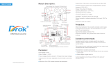
Fig. 4-1 Internal Bus Communication System
2. Internal Communication Bus
The SYA block carries out overall control of camera operation by detecting the input from the keyboard and the condition of the
camera circuits. The 8-bit microprocessor reads the signals from each sensor element as input data and outputs this data to the
camera circuits (ASIC) or to the LCD display device as operation mode setting data. Fig. 4-1 shows the internal communication
between the 8-bit microprocessor and ASIC.
8-bit micro processor ASIC
MRST
ZTEST
PLLEN
SI
SO
SCK
SREQ
communi-
cation
COMREQ
setting of
external port
TELE WIDE
MENU

– 9 –
ASIC,
memory
CCD
8bit
CPU
LCD
MONITOR
Power supply voltage
Power OFF
Playback mode
Shooting mode (OVF)
Shooting
USB connection
1.53 V, 3.25 V
4.7 V, -8 V
3.45 V
3.2 V
15 V, 5.0 V
OFF
OFF
32KHz
OFF
ON
OFF
4MHz
ON
ON
OFF
4MHz
ON
OFF
OFF
4MHz
OFF
ON
ON
4MHz
ON
ON
OFF
4MHz
OFF
Table 4-3. Power supply control
Shooting mode (LCD)
4. Power Supply Control
The 8-bit microprocessor controls the power supply for the overall system.
The following is a description of how the power supply is turned on and off. When the battery is attached, IC955 is operating and
creating 3.6 V, a regulated 3.2 V voltage is normally input to the 8-bit microprocessor (IC301) by IC302, clock counting and key
scanning is carried out even when the power switch is turned off, so that the camera can start up again.
When the power switch is off, the 8-bit microprocessor halts 4 MHz of the main clock, and operates 32.768 kHz of subclock.
When the battery is removed, the 8-bit microprocessor power switches the lithum secondary battery for memory backup by
IC302, and operates at low consumption. At this condition, the 8-bit microprocessor halts the main clock, and operates clock
counting by sub clock.
Also, the battery for backup is charged 10 hours from it to be attached.
When the power switch is on, the 8-bit microprocessor starts processing. The 8-bit microprocessor first sets both the PON signal
at pin (32) and the PAON signal at pin (33) to High, and then turn on the power circuit. After PON signal is to High, sets external
port of ASIC after approximately 100 ms. According to setting of this external port, carry out setting of the operating frequency
and oscillation control in the ASIC. Also, it starts communication with ASIC, and confirms the system is operative.
When the through image is operating, set the PAON signal to High and then turn on the CCD. When the through image is playing,
set the PAON signal to Low and then turn off the CCD. When LCD panel turns on, set LCD ON signal at pin (34), LCD ON2 signal
at pin (31) and LCD ON3 signal at pin (36) to High, and then turn on the power. Set LCD BL signal at pin (35) to High, and turn
on the backlight power.
When the power switch is off, the lens will be stowed, and PON, PAON, LCDON and BLON signals to Low and the power supply
to the whole system is halted. The 8-bit microprocessor halts oscillation of the main clock, and set operation mode of clock
ocillation.

– 10 –
2. DISASSEMBLY
2-1. REMOVAL OF CABINET BACK AND CABINET FRONT
1. Five screws 1.7 x 4.5
2. Open the cover battery.
3. Cabinet back
4. Cabinet front
1
1
1
2
3
4
NOTE: Discharge a strobe capacitor
with the discharge jig (VJ8-0188) for
electric shock prevention.

– 11 –
2-2. REMOVAL OF LCD, CP1 BOARD, TB1 BOARD, ST1 BOARD, LENS ASSEMBLY, TB2 BOARD AND BOARD LOCATION
1. FPC
2. Connector
3. LCD
4. Three screws 1.7 x 4
5. Holder monitor
6. Two screws 1.7 x 4
7. FPC
8. FPC
9. FPC
10. Remove the solder.
11. Spacer TB2
12. Remove the solder.
13. Three screws 1.6 x 3.5
A
A
B
B
C
C
D
E
E
D
1
2
3
4
5
6
7
8
9
10
11
12
13
14
15
16
17
18
19
20
21
22
23
24
25
26
14. CP1 board
15. Two screws 1.7 x 4
16. Earth plate
17. TB1 board
18. Two screws 1.7 x 4
19. Remove the solder.
20. ST1 board
21. Three screws 1.7 x 4
22. Lens assembly
23. Spacer fuse up
24. Spacer fuse
25. Screw 1.7 x 4
26. TB2 board
TB2 board
CP1 board
TB1 board
ST1 board

– 12 –
3. ELECTRICAL ADJUSTMENT
3-1. Table for Servicing Tools
Note: J-1 Pattern box (color viewer) is 100 - 110 VAC only.
3-2. Equipment
1. Oscilloscope
2. Digital voltmeter
3. AC adaptor
4. PC (IBM R -compatible PC, Pentium processor, Window
98 or Me or 2000 or XP)
3-3. Adjustment Items and Order
1. IC501 Oscillation Frequency Adjustment
2. Lens Adjustment
3. AWB Adjustment
4. CCD White Point Defect Detect Adjustment
5. CCD Black Point And White Point Defect Detect Adjust-
ment In Lighted
6. LCD Panel Adjustment
6-1. LCD VcomPP Adjustment
6-2. LCD VcomDC Adjustment
Note: If the lens, CCD and board in item 2-5, it is necessary
to adjust again. Item 2-4 adjustments should be carried
out in sequence. Item 5 adjustment should be carried
out after item 3.
3-4. Setup
1. System requirements
Windows 98 or Me or 2000 or XP
IBM R -compatible PC with pentium processor
CD-ROM drive
3.5-inch high-density diskette drive
USB port
40 MB RAM
Hard disk drive with at least 15 MB available
VGA or SVGA monitor with at least 256-color display
2. Installing calibration software
1. Insert the calibration software installation diskette into your
diskette drive.
2. Open the explorer.
3. Copy the DscCalDI_140 folder on the floppy disk in the FD
drive to a folder on the hard disk.
3. Installing USB driver
Install the USB driver with camera or connection kit for PC.
4. Pattern box (color viewer)
Turn on the switch and wait for 30 minutes for aging to take
place before using Color Pure. It is used after adjusting the
chroma meter (VJ8-0192) adjust color temperature to 3100 ±
20 K and luminosity to 900 ± 20 cd/m
2
. Be careful of handling
the lump and its circumference are high temperature during
use and after power off for a while.
5. Computer screen during adjustment
Ref. No.
Name
Part code
J-1
J-2
J-3
VJ8-0190
VJ8-0237
Pattern box (color viewer)
Siemens star chart
Calibration software
J-4
Number
1
1
1
1Chroma meter
VJ8-0192
1
Spare lump
VJ8-0191
J-5
J-1 J-2
J-3
J-4
J-5
1
Discharge jig
VJ8-0188
J-6
J-6
Firmware
Image
AWB
Focus
UV Matrix
R Bright
RGB Offset
Tint
B Bright
Gain
Phase
LCD
Calibration
Upload
Initialize
LCD Type
H AFC Test
VCOMDC
VCOMPP
Cal Data
Cal Mode
OK
OK
EVF
USB storage
Get
Set
VID
Set
PID
Set
Serial
Set
Rev.
Set
Setting
Language
Video Mode
VCO
Factory Code
Hall Cal.

– 13 –
3-5. Connecting the camera to the computer
1. Line up the arrow on the cable connector with the notch on the camera's USB port. Insert the connector.
2. Locate a USB port on your computer.
AC adaptor
To USB port
USB cable

– 14 –
3-6. Adjust Specifications
[CP1 board (Side B)]
Note:
1. Frequency adjustment is necessary to repair in the CP1
board and replace the parts.
2. Power voltage sets about +3.0 V.
Preparation:
1. Remove the cabinet back and holder monitor. You can see
VR501 and CL541 in the CP1 board.
Note: LCD flexible flat cable and backlight lead wire keep
connecting. When assembling, holder monitor and metal
part of LCD panel should not contact a substrate.
2. Insert the SD card.
3. Turn on the power switch, and set the camera mode.
1. IC501 Oscillation Frequency Adjustment
Adjustment method:
1. Adjust with VR501 to 499.6 ± 1 kHz.
2. Lens Adjustment
Preparation:
POWER switch: ON
Adjustment condition:
More than A3 size siemens star chart
Fluorescent light illumination with no flicker
Illumination above the subject should be 400 lux ± 10 %.
Adjustment method:
1. Set the siemens star chart 60 cm so that it becomes center
of the screen.
2. Connect the camera and the computer with USB cable.
3. Set the main switch to PC.
4. Select “OK”, and press the SET button.
5. Double-click on the DscCalDi.exe.
6. Click the Focus, and click the Yes.
7. Lens adjustment value will appear on the screen.
8. Click the OK.
Adjustment value determination is effectuated using the
"P(PRW)", “P(BR)” and "FOCUS" values.
If FOCUS=f1, f2, f3, f4 and the adjustment values fulfill the
conditions below, they are determined as within specifications.
Adjustment value determination
7<=prw<=75
pbr<=40
-67<=f1<=67
-99<=f2<=101
-110<=f3<=130
-111<=f4<=183
Measuring Point
ADJ. Location
Measuring Equipment
ADJ. Value
CL541
Frequency counter
VR501
499.6 ± 1 kHz
CL401
CL402(GND)
CL541
VR501
DscCalDi x
OK
Focus Result
P(PRW)=47
P(BR)=18
FOCUS=4,2,-2,-6
!
Camera
Approx.
60 cm 2 cm
Siemens
star chart

– 15 –
3. AWB Adjustment
Preparation:
POWER switch: ON
Adjusting method:
1. When setting the camera in place, set it to an angle so that
nothing appears in any part of the color viewer except the
white section. (Do not enter any light.)
2. Double-click on the DscCalDi.exe.
3. Click the AWB, and click the Yes.
4. AWB adjustment value will appear on the screen.
5. Click the OK.
Adjustment value determination is effectuated using the "AGC",
“CHECK" and "MS" values.
If AGC=a1, a2, a3, a4, a5, CHECK=wc0, wc1, wc2 and
MS=MS1, MS2, the adjustment values fulfill the conditions be-
low, they are determined as within specifications.
Adjustment value determination
150<a1<350, 330<a2<540, 450<a3<680,
600<a4<850, 800<a5<1024
wc0=128 ± 2, wc1=128 ± 2, wc2=130 ± 40
2500<=MS1<=4500
2900<=MS2<=5200
150<IRIS<220
Adjustment values other than the above are irrelevant.
4. CCD White Point Defect Detect Adjustment
Preparation:
POWER switch: ON
Adjustment method:
1. Double-click on the DscCalDi.exe.
2. Select “CCD Defect” on the LCD “Test”, and click the “Ye s ”.
3. After the adjustment is completed, OK will display.
4. Click the OK.
5. CCD Black Point And White Point Defect Detect
Adjustment In Lighted
Preparation:
POWER switch: ON
Setting of pattern box:
Color temperature: 3100 ± 20 (K)
Luminance: 900 ± 20 (cd/m
2
)
Adjusting method:
1. Set the camera 0 cm from the pattern box. (Do not enter
any light.)
2. Double-click on the DscCalDi.exe.
3. Select “CCD Black” on the LCD “Test”, and click the “Ye s ”.
4. After the adjustment is completed, the number of defect
will appear.
Camera
Pattern box
(color viewer)
Camera
Pattern box
(color viewer)
Dsc Calibration
x
OK
AWB Result:
1:
AGC=220,388,481,724,892
3F_AGC=0,0
WB=237,511,501
CHECK=128,128,140
MS=3472,3565
0
IRIS=179
Copy

– 16 –
6. LCD Panel Adjustment
[CP1 board (Side B)]
6-1. LCD VcomPP Adjustment
Preparation:
POWER switch: ON
Adjusting method:
1. Double-click on the DscCalDi.exe.
2. Adjust LCD “VCOMPP” so that the amplitude of the CL401
waveform is 5.60 V ± 0.05 Vp-p.
6-2. LCD VcomDC Adjustment
Adjusting method:
1. Adjust LCD “VCOMDC” so that the amplitude of the CL401
waveform is 4.10 V ± 0.05 Vp-p.
CL401 waveform
5.60 V
± 0.05 Vp-p
CL401 waveform
4.10 V
± 0.05 Vp-p
GND
(CL402)
3-7. Factory Code Setting
1. Check the "Factory Code" display within the Setting group.
2. For U.S.A., Canada and NTSC general area
If "FC_SANYO_U" does not appear, click on the " " mark
located on the right of the "Factory Code" display BOX and
select "FC_SANYO_U".
3. For Europe and PAL general area
If "FC_SANYO_EX" does not appear, click on the " " mark
located on the right of the "Factory Code" display BOX and
select "FC_SANYO_EX".
3-8. Language Setting
1. Click on the " " mark located on the right of the
"Language" display BOX.
2. Select language. (Default is English.)
3. End "DscCal" and remove the camera before turning the
camera power OFF.
CL401
CL402(GND)
CL541
VR501
Firmware
Image
AWB
Focus
UV Matrix
R Bright
RGB Offset
Tint
B Bright
Gain
Phase
LCD
Calibration
Upload
Initialize
LCD Type
H AFC Test
VCOMDC
VCOMPP
Cal Data
Cal Mode
OK
OK
EVF
USB storage
Get
Set
VID
Set
PID
Set
Serial
Set
Rev.
Set
Setting
Language
Video Mode
VCO
Factory Code
Hall Cal.

– 17 –
4. USB STORAGE INFORMATION
REGISTRATION
USB storage data is important for when the camera is con-
nected to a computer via a USB connection.
If there are any errors in the USB storage data, or if it has not
been saved, the USB specification conditions will not be sat-
isfied, so always check and save the USB storage data.
Preparation:
POWER switch: ON
Adjustment method:
1. Connect the camera to a computer. (Refer to 3-5. Con-
necting the camera to the computer on the page 13.)
2. Double-click on the DscCalDi.exe.
3. Click on the Get button in the USB storage window and
check the USB storage data.
VID: SANYO
PID: S3
Serial:
Rev. : 1.00
4. Check the “Serial” in the above USB storage data. If the
displayed value is different from the serial number printed
on the base of the camera, enter the number on the base
of the camera. Then click the Set button.
5. Next, check VID, PID and Rev. entries in the USB storage
data. If any of them are different from the values in 3. above,
make the changes and then click the corresponding Set
button.
Firmware
Image
AWB
Focus
UV Matrix
R Bright
RGB Offset
Tint
B Bright
Gain
Phase
LCD
Calibration
Upload
Initialize
LCD Type
H AFC Test
VCOMDC
VCOMPP
Cal Data
Cal Mode
OK
OK
EVF
USB storage
Get
Set
VID
Set
PID
Set
Serial
Set
Rev.
Set
Setting
Language
Video Mode
VCO
Factory Code
Hall Cal.

– 18 –
5. TROUBLESHOOTING GUIDE
POWER LOSS INOPERTIVE
PUSH THE POWER
SW
IC301-15
(SCAN IN 0)
PULSE INPUT
CHECK SYA BLOCK
IC302-7
3.6 V
CHECK
POWER CIRCUIT
IC301-17, 29
(VDD)
IC301-25
(RESET)
CHECK IC302
CHECK IC302
IC301-12
(BAT OFF)
CHECK IC303,
D3002, D3003
IC301-27
OSCILLATION
CHECK X3001
IC301-24
OSCILLATION
CHECK X3002,
R3009, C3010, C3011
CHECK IC301
PUSH RELEASE
SWITCH
SB LED IS FLASHING
WHEN AUTO
LUMINOUS (RED)
STROBE CHARGE
INOPERATIVE
CHECK STA BLOCK
CN301-5, 6
(SCAN IN 1, 2)
PULSE INPUT
CHECK
SYA BLOCK
CHECK
DMA BLOCK
TAKING INOPERATIVE
NO
NO
LOW
LOW
LOW
NO
NO
YES
YES
HIGH
HIGH
HIGH
YES
YES
NO
YES
YES
NO

19
6. PARTS LIST
LOCATION PARTS NO. DESCRIPTION LOCATION PARTS NO. DESCRIPTION
1 636 069 5337 STRAP HAND-SX711/J
2 645 059 6148 CABLE,DSC USB,SX781
3 645 067 7854 DISC,CD-ROM SSP 715 U (N.S.P.)
Sanyo software pack & PDF of Instruction manual
(English, Spanish,Chinese, German, French, Dutch,
Italian, Korean)
4 636 077 9334 INSTRUCTION MANUAL
CAMERA & SOFTWARE(English)
7001 636 079 2142 CARTON CASE INNER-715/EX
7002 636 078 4659 CUSHION SHEET-SX792/KRNK
7003 636 078 4185 REINFORCE PAD,A-SX715/EX BOTTOM
ACCESSORIES
PACKING MATERIALS
1
2
3

20
CABINET & CHASSIS PARTS 1
N.S.P.: Not available as service parts.
LOCATION PARTS NO. DESCRIPTION LOCATION PARTS NO. DESCRIPTION
1 636 078 2433 DEC LENS-SX715/EX
2 636 078 2426 DEC VF-SX715/EX
3 636 078 2419 DEC RING-SX715/EX
4 636 078 7988 ADHESIVE DEC GRIP-SX715
5 636 078 2440 DEC GRIP-SX715/EX
6 636 078 2372 CABINET LEFT-SX715/EX
7 636 064 4977 SPRING SHUTTER-SX541/JM
8 636 078 2334 BUTTON SHUTTER-SX715/EX
9 636 078 2341 BUTTON POWER-SX715/EX
10 636 078 8114 SPACER ST1-SX715/EX
11 636 078 2501 REFLECTOR LED-SX715/EX
12 636 078 2402 DEC FLASH-SX715/EX
13 636 078 7971 ADHESIVE DEC FLASH-SX715
14 636 078 2365 CABINET FRONT-SX715/EX
15 636 078 2396 COVER BATTERY-SX715/EX
16 636 078 2877 TERMINAL BATT D-SX715/EX
17 636 078 2785 CAP BATT TERMINAL-SX715EX
18 636 078 2860 TERMINAL BATT C-SX715/EX
19 636 078 2525 SPACER MONITOR-SX715/EX
20 636 078 2495 REFLECTOR VF-SX715/EX
21 636 078 2310 BUTTON SELECT-SX715/EX
22 636 078 2808 SLIDE FUNCTION-SX715/EX
23 636 078 2327 BUTTON ZOOM-SX715/EX
24 636 078 2358 CABINET BACK-SX715/EX
25 636 078 2488 KNOB FUNCTION-SX715/EX
26 636 080 5385 SPACER LCD WIRE-SX715/EX
27 636 081 6473 SPACER FLASH-SX715/EX
101 411 176 9405 SCR S-TPG PAN PCS 1.7X4.5
102 411 177 9503 SCR S-TPG PAN PCS 1.7X3
103 412 060 4506 SPECIAL SCREW-1.7X2.2
SX715/EX Parts List 1
1
2
3
4
5
6
7
8
9
10
11
12
13
14
19
20
21
22
23
24
25
26
101
101
102
102
102
101
101
101
15
16
17
18
103
27
/