Blade BLH1180 Owner's manual
- Category
- Remote controlled toys
- Type
- Owner's manual
This manual is also suitable for

Instruction Manual
Bedienungsanleitung
Manuel d’utilisation
Manuale di Istruzioni

2
EN
• Always keep a safe distance in all directions around
your model to avoid collisions or injury. This model is
controlled by a radio signal subject to interference from
many sources outside your control. Interference can
cause momentary loss of control.
• Always operate your model in open spaces away from
full-size vehicles, traffi c and people.
• Always carefully follow the directions and warnings
for this and any optional support equipment (chargers,
rechargeable battery packs, etc.).
• Always keep all chemicals, small parts and anything
electrical out of the reach of children.
• Always avoid water exposure to all equipment not
specifi cally designed and protected for this purpose.
Moisture causes damage to electronics.
• Never place any portion of the model in your mouth as it
could cause serious injury or even death.
• Never operate your model with low transmitter batteries.
• Always keep aircraft in sight and under control.
• Always move the throttle fully down at rotor strike.
• Always use fully charged batteries.
• Always keep transmitter powered on while aircraft is
powered.
• Always remove batteries before disassembly.
• Always keep moving parts clean.
• Always keep parts dry.
• Always let parts cool after use before touching.
• Always remove batteries after use.
• Never operate aircraft with damaged wiring.
• Never touch moving parts.
Safety Precautions and Warnings
Age Recommendation: Not for children under 14 years. This is not a toy.
NOTICE
All instructions, warranties and other collateral documents are subject to change at the sole discretion of Horizon
Hobby, LLC. For up-to-date product literature, visit horizonhobby.com or towerhobbies.com and click on the support or
resources tab for this product.
Meaning of Special Language
The following terms are used throughout the product literature to indicate various levels of potential harm when
operating this product:
WARNING: Procedures, which if not properly followed, create the probability of property damage, collateral damage,
and serious injury OR create a high probability of superfi cial injury.
CAUTION: Procedures, which if not properly followed, create the probability of physical property damage AND a
possibility of serious injury.
NOTICE: Procedures, which if not properly followed, create a possibility of physical property damage AND a little or no
possibility of injury.
WARNING: Read the ENTIRE instruction manual to become familiar with the features of the product before
operating. Failure to operate the product correctly can result in damage to the product, personal property and
cause serious injury.
This is a sophisticated hobby product. It must be operated with caution and common sense and requires some basic
mechanical ability. Failure to operate this Product in a safe and responsible manner could result in injury or damage
to the product or other property. This product is not intended for use by children without direct adult supervision. Do
not use with incompatible components or alter this product in any way outside of the instructions provided by Horizon
Hobby, LLC. This manual contains instructions for safety, operation and maintenance. It is essential to read and follow
all the instructions and warnings in the manual, prior to assembly, setup or use, in order to operate correctly and avoid
damage or serious injury.

3
EN
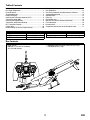
Box Contents
• Blade 120 S2
• 500mAh 1S 3.7V 25C Li-Po Battery
• 1S Li-Po USB Charger
• MLP6DSM SAFE 6 Channel Transmitter (RTF Only)
• 4 AA Batteries (RTF Only)
Table of Contents
Length
12.6 in (320mm)
Height
4.25 in (108mm)
Main Rotor Diameter
13 in (330mm)
Tail Rotor Diameter
2.75 in (70mm)
Flying Weight
3.74 oz (106 g)
Specifications
Box Contents .................................................................... 3
First Flight Preparation ...................................................... 4
Flying Checklist ................................................................ 4
Charging Warnings............................................................ 4
Battery Charging ............................................................... 4
Installing the Transmitter Batteries (RTF) ........................... 5
Transmitter Setup (BNF) .................................................... 5
Installing the Flight Battery ...............................................8
Transmitter and Receiver Binding ...................................... 8
RTF Transmitter Controls ..................................................9
Control Tests ................................................................... 10
Understanding the Primary Flight Controls ...................... 10
Flying the 120 S2............................................................ 11
Drift Calibration............................................................... 12
Post-Flight Inspection and Maintenance Checklist ........... 12
Troubleshooting Guide .................................................... 12
Exploded View ................................................................ 14
Parts List ........................................................................ 14
Limited Warranty ............................................................ 15
Warranty and Service Contact Information ...................... 16
FCC Information .............................................................. 16
IC Information ................................................................. 16
Compliance Information for the European Union .............. 17

4
EN
CAUTION: All instructions and warnings must be
followed exactly. Mishandling of Li-Po batteries can
result in a fi re, personal injury and/or property damage.
• NEVER LEAVE CHARGING BATTERIES UNATTENDED.
• NEVER CHARGE BATTERIES OVERNIGHT.
• By handling, charging or using the included Li-Po
battery, you assume all risks associated with lithium
batteries.
• If at any time the battery begins to balloon or swell,
discontinue use immediately. If charging or discharging,
discontinue and disconnect. Continuing to use, charge
or discharge a battery that is ballooning or swelling can
result in fi re.
• Always store the battery at room temperature in a dry
area for best results.
• Always transport or temporarily store the battery in a
temperature range of 40–120º F (5–49° C).
• Do not store battery or model in a car or direct sunlight.
If stored in a hot car, the battery can be damaged or
even catch fi re.
• Always charge batteries away from fl ammable
materials.
• Always inspect the battery before charging
• Always disconnect the battery after charging, and let the
charger cool between charges.
• Always constantly monitor the temperature of the
battery pack while charging.
• ONLY USE A CHARGER SPECIFICALLY DESIGNED TO
CHARGE LI-PO BATTERIES. Failure to charge the battery
with a compatible charger may cause a fi re resulting in
personal injury and/or property damage.
• Never discharge Li-Po cells to below 3V under load.
• Never cover warning labels with hook and loop strips.
• Never charge batteries outside recommended levels.
• Never charge damaged batteries.
• Never attempt to dismantle or alter the charger.
• Never allow minors to charge battery packs.
• Never charge batteries in extremely hot or cold places
(recommended between 40–120° F or (5–49° C) or
place in direct sunlight.
NOTICE: Charge only batteries that are cool to the touch
and are not damaged. Look at the battery to make sure it
is not damaged e.g., swollen, bent, broken or punctured.
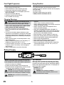
1. Insert the charger into a USB port.
2. Properly connect the battery to the charger lead.
3. Always disconnect the fl ight battery from the charger
immediately upon completion of charging.
CAUTION: Only use chargers specifi cally designed
to charge the included Li-Po battery. Failure to do
so could result in fi re, causing injury or property damage.
CAUTION: Never exceed the recommended
charge rate.
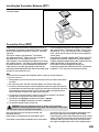
LED Indications
When you make the connection successfully, the LED on
the charger turns solid red, indicating charging has begun.
Charging a fully discharged (not over-discharged) 500mAh
battery takes approximately 60 minutes. The light goes off
when the charge is complete.
CHARGING (Solid Red)
MAX CHARGE (OFF)
CAUTION: Once charging is complete,
immediately remove the battery. Never leave a
battery connected to the charger.
Charging Warnings
Battery Charging
First Flight Preparation
• Remove and inspect contents
• Begin charging the fl ight battery
• Install the batteries in the transmitter (RTF only)
• Program your computer transmitter (BNF only)
• Install the fl ight battery in the helicopter (once it has
been fully charged)
• Bind your transmitter (BNF only)
• Familiarize yourself with the controls
• Find a suitable area for fl ying
Flying Checklist
❏ Always turn the transmitter on fi rst
❏ Plug the fl ight battery into the lead from the ESC
❏ Allow the receiver and ESC to initialize and arm properly
❏ Fly the model
❏ Land the model
❏ Unplug the fl ight battery from the ESC
❏ Always turn the transmitter off last
USB Li-Po
Charger
EFLC1010
SOLID RED LED
–Charging
DC Input:5.0V 500mA
DC Output:4.2V 500mA
LED OFF
–Charge
Complete

5
EN
Installing the Transmitter Batteries (RTF)
Replace the transmitter batteries when the
transmitter beeps.
Transmitter Setup (BNF)
Program your transmitter before attempting to bind or fl y
the helicopter. Transmitter programming values are shown
below for the Spektrum DX6i, DX7s, DX6, DX7, DX8, DX9
and DX18.
The fi les for models using Spektrum
™
transmitters
with Spektrum AirWare
™
software are also available for
download online at www.spektrumrc.com.
Your helicopter is also compatible with Spektrum DXe radios
with software version 1.3 or higher. Use the directions below
to reverse channel 6, or use the appropriate programming
cable and the PC or mobile app to program the DXe. We
recommend downloading the Blade 120 S2 DXe model setup
available at www.spektrumrc.com.
If you are programming your DXe using the PC or mobile
app, make sure the "Transmitter Channels" value is set to
the default of 7. If for any reason this value is changed to
9, the 120 S2 will bind to the DXe, but will not respond to
control inputs.
If your DXe was included in another Blade
®
Ready To Fly (RTF)
helicopter, the transmitter software will have to be updated
using the appropriate programming cable and either the PC or
mobile app available at www.spektrumrc.com.
Please note, the switch confi guration used for DXe
transmitters included with the Blade 230 S RTF and Micro AH-
64 Apache™ RTF varies from the standard DXe layout.
To use the DXe transmitter with the Blade 120 S2, channel 6 must be reversed.
To reverse channel 6:
1. While powering on the DXe, hold the left and right sticks in the top-inside corners
as shown.
2. Re-center the sticks after the transmitter beeps. The LED will fl ash slowly.
3. To select a channel to reverse, move the right stick to the left or right and allow it to
re-center. Move the stick to the right to select the next channel. Move the stick to the
left to select the previous channel. The LED will fl ash rapidly corresponding to the
channel selected, as shown in the table. Select channel 6.
4. To reverse the selected channel, move the right stick up or down. The LED will
change color to indicate the new channel direction.
5. The LED will fl ash Orange to indicate the channel is normal.
The LED will fl ash Red to indicate the channel is reversed.
6. To store the changes, power off the DXe.
CAUTION: During the subsequent power up, always verify the throttle
direction is correct and keep clear of the motor and rotor blades. Failure to do
so may result in injury or damage to the product.
DXe
LED Flashes Channel
1 1-Throttle
2 2-Aileron
3 3-Elevator
4 4-Rudder
5 5-Flight Mode
6 6-Panic
7 7-Flaps
8 8-Aux Channel
After reversing channel 6, bind the transmitter and
helicopter normally.
Flight modes are controlled by the Flight Mode switch.
Panic Mode is controlled by the Bind/Panic/Trainer button.
Once bound, the LED in the helicopter should glow green
blue or red, depending on the fl ight mode selected.
If the LED glows green in FM-0 mode or blue in FM-1/FM-2
modes, channel 6 has not been reversed correctly. Use the
directions above to reverse channel 6. If the LED fl ashes
red, replace the fl ight battery with a fully charged battery.

6
EN
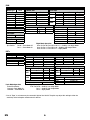
Servo Setup
FUNCTION LISTSYSTEM SETUP
DX7s
Throttle Cut
Switch Mix 1
D/R & Expo
Chan
Switch Pos (FLAP)
D/R
Expo*
AILE
0 100/100 0
1 100/100 0
2 75/75 0
ELEV
0 100/100 0
1 100/100 0
2 75/75 0
D/R & Expo
Chan
Switch Pos (FLAP)
D/R
Expo*
RUDD
0 100/100 0
1 100/100 0
2 75/75 0
Timer
Mode Count Down
Time 5:00 Tone
Start Throttle Out
Pos 25%
Chan Travel Reverse
THR 100/100 Normal
AIL 100/100 Normal
ELE 100/100 Normal
RUD 100/100 Normal
Chan Travel Reverse
GER 100/100 Normal
AX1 100/100 Reverse
AX2 100/100 Normal
Panic Mode Operation
Trainer/Bind Button
Pressed = Panic Mode On
Released = Panic Mode Off
Model Type ACRO
SW Select
Trainer Aux 1
Flap Gear
All Others INH
* Use of "Expo" is not necessary for successful fl ight of the 120 S2. The pilot may adjust this setting to tailor the
sensitivity of the helicopter around neutral if desired.
D/R & Expo
Chan Sw Pos D/R Expo*
AILE
0 100 INH
1 75 INH
ELEV
0 100 INH
1 75 INH
RUDD
0 100 INH
1 75 INH
Timer
Down Timer 5:00
Switch THR CUT
ADJUST LISTSETUP LIST
DX6i
TRAVEL ADJ
Channel Travel
THRO 100/100
AILE 100/100
ELEV 100/100
RUDD 100/100
GEAR 100/100
PITC 100/100
REVERSE
Channel Direction
THRO N
AILE N
ELEV N
RUDD N
GEAR R
FLAP N
Modulation Type
AUTO DSMX-ENABLE
D/R COMBI
D/R SW AILE
Model Type Acro
Panic Mode Operation
Gyro Switch: Pos 0 = Panic Mode Off
Pos 1 = Panic Mode On
Flight Mode Operation
Gear Sw: Pos 0, Elev D/R Sw: 0 or 1 = Stability, Low-Angle Mode
Gear Sw: Pos 1, Elev D/R Sw: 0 = Stability, High-Angle Mode
Gear Sw: Pos 1, Elev D/R Sw: 1 = Agility Mode
Flight Mode Operation
FLAP Sw: Pos 0 = Stability, Low-Angle Mode
Pos 1 = Stability, High-Angle Mode
Pos 2 = Agility Mode
Mixing
MIX 1 ACT
GEAR > GEAR ACT
RATE D 0% U –100%
SW GEAR TRIM – INH
MIX 2 ACT
GEAR > GEAR ACT
RATE D 0% U +100%
SW ELE D/R TRIM – INH
FLAPS
FLAP ELEV
NORM 100 0
LAND 100 0

7
EN
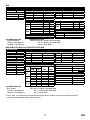
Servo Setup
FUNCTION LISTSYSTEM SETUP
DX8
SYSTEM SETUP
Model Type Airplane
F-Mode Setup
Switch 1 Switch B
Switch 2 Inhibit
Channel Assign
Channel Input
1 Throttle N/A
2 Aileron N/A
3 Elevator N/A
4 Rudder N/A
5 Gear B
6 AUX 1 I
Throttle Cut
Position –130
Switch Switch H
0
1
Throttle Cut
Switch Mix 1
Chan Travel Reverse
THR 100/100 Normal
AIL 100/100 Normal
ELE 100/100 Normal
RUD 100/100 Normal
GER 100/100 Normal
Chan Travel Reverse
AX1 100/100 Reverse
AX2 100/100 Normal
AX3 100/100 Normal
AX4 100/100 Normal
Servo Setup
FUNCTION LIST
DX6, DX6e, DX7 (Gen 2), 8e, DX9, DX18, iX12, iX20
Timer
Mode Count Down
Time 5:00
Start Throttle Out
Over 25%
One Time Inhibit
D/R & Expo
Chan
Switch (F) Pos
D/R Expo*DX6
DX7, 9,
18
AILE
0 0 100/100 0
1 100/100 0
1 2 75/75 0
ELEV
0 0 100/100 0
1 100/100 0
1 2 75/75 0
RUDD
0 0 100/100 0
1 100/100 0
1 2 75/75 0
D/R & Expo
Chan
Switch Pos (AIL D/R)
D/R
Expo*
AILE
0 100/100 0
1 100/100 0
2 75/75 0
ELEV
0 100/100 0
1 100/100 0
2 75/75 0
D/R & Expo
Chan
Switch Pos (AIL D/R)
D/R
Expo*
RUDD
0 100/100 0
1 100/100 0
2 75/75 0
Timer
Mode Count Down
Time 5:00 Tone
Start Throttle Out
Pos 25%
Chan Travel Reverse
THR 100/100 Normal
AIL 100/100 Normal
ELE 100/100 Normal
RUD 100/100 Normal
Chan Travel Reverse
GER 100/100 Normal
AX1 100/100 Reverse
AX2 100/100 Normal
Panic Mode Operation
Trainer/Bind Button
Pressed = Panic Mode On
Released = Panic Mode Off
Model Type ACRO
SW Select
Trainer Aux 1
F Mode Gear
All Others INH
Panic Mode Operation
Bind / I Button
Pressed = Panic Mode On
Released = Panic Mode Off
* Use of "Expo" is not necessary for successful fl ight of the 120 S2. The pilot may adjust this setting to tailor the
sensitivity of the helicopter around neutral if desired.
Flight Mode Operation
F MODE Sw: Pos 0 = Stability, Low-Angle Mode
Pos 1 = Stability, High-Angle Mode
Pos 2 = Agility Mode
Flight Mode Operation
Sw B: Pos 0 = Stability, Low-Angle Mode
Pos 1 = Stability, High-Angle Mode
Pos 2 = Agility Mode

8
EN
Transmitter and Receiver Binding
Installing the Flight Battery
A B
C
* The trigger switch may also be used for the binding procedure.
If you encounter problems, obey binding instructions and refer to the troubleshooting guide for other instructions. If needed, contact
the appropriate Horizon Product Support offi ce.
Your RTF transmitter comes prebound to the model. If you need to re-bind, follow the directions below.
1. Lower the throttle stick to the lowest position (A) and
center all trims.
2. Set the fl ight mode switch to Stability, Low Bank Angle
Mode (FM-0)
3. Power ON the transmitter (B).
4. Slide the fl ight battery fully into the mount of the
helicopter frame (C).
5. Connect the power lead to the battery (D), noting the
correct polarity.
CAUTION: Connecting the battery to the control
board with reversed polarity will cause damage
to the control board, the battery or both. Damage caused
by incorrectly connecting the battery is not covered
under warranty.
6. Keep the aircraft from moving. The LED quickly fl ashes
red followed by a quick green fl ash and then cycles red,
green, blue and red, indicating initialization is complete.
After initialization is complete:
• If the aircraft is bound correctly to the transmitter, the LED
will change to show the currently selected fl ight mode.
• If the LED on the control board fl ashes blue rapidly,
indicating the aircraft is in bind mode, proceed to the
Transmitter and Receiver Binding section to bind the
aircraft and transmitter.
• If the LED fl ashes blue slowly, the fl ight controller lost
communication with the transmitter.
• If the LED fl ashes red, the fl ight controller has hit the
low voltage cutoff (LVC). Replace the fl ight battery with
a fully charged battery.
CAUTION: Always disconnect the Li-Po battery
from the aircraft when not fl ying to avoid
over-discharging the battery. Batteries discharged to a
voltage lower than the lowest approved voltage may
become damaged, resulting in loss of performance and
potential fi re when batteries are charged.
MLP6DSM Binding Procedure (RTF)
1. Disconnect the fl ight battery from the helicopter.
2. Center all trims on your transmitter.
3. Power off the transmitter and move the throttle stick to the down/off position.
4. Connect the fl ight battery in the helicopter, and keep the helicopter from moving. The LED on the control board
continually fl ashes blue after the aircraft initializes, indicating the control board is in bind mode.
5. Push in and hold down the left stick* while powering on the transmitter (you will hear a ‘click’).
6. Release the left stick. The transmitter will beep and the power LED will blink.
7. The helicopter is bound when the LED on the control board is solid (not blinking).
8. Disconnect the fl ight battery and power the transmitter off.

9
EN
To bind or re-bind your helicopter to your chosen transmitter, follow the directions below.
General Binding Procedure (BNF)
1. Disconnect the fl ight battery from the helicopter.
2. Refer the Transmitter Setup Table to correctly setup your transmitter.
3. Lower the throttle stick to the lowest position and center all trims on your transmitter.
4. Power off the transmitter and move all switches to the 0 position. Move the throttle to the low/off position.
5. Connect the fl ight battery to the control board. The control board LED rapidly fl ashes blue, indicating it is in bind mode.
6. Put the transmitter into bind mode while powering on the transmitter.
7. Release the bind button/switch after 2–3 seconds. The helicopter is bound when the LED on the receiver turns solid.
8. Disconnect the fl ight battery and power the transmitter off.
CAUTION: When using a Futaba
®
transmitter with a Spektrum
™
DSM2
®
module, you must reverse the throttle
channel and re-bind. Refer to your Spektrum module manual for binding and failsafe instructions. Refer to your
Futaba transmitter manual for instructions on reversing the throttle channel.
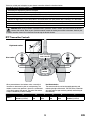
RTF Transmitter Controls
D
E
C
B
Flight mode switch
Bind switch
Dual rate
switch
ON/OFF
Switch
Power LED/fl ight
mode indicator
AF
When pressed down, trim buttons make a sound that
increases or decreases in pitch at each pressing. The
middle or neutral trim position is heard as a middle tone
in the pitch range of the sounds. The end of the control
range is sounded by a series of beeps.
Dual Rate Selection
The control sensitivity can be changed by pressing and
releasing the right control stick. The LED on the transmitter
will show solid for high sensitivity (default) and fl ashing for
low sensitivity.
ABCDE F
Mode 2
Aileron (Left/Right)
Elevator (Up/Down)
Elevator
Trim
Aileron
Trim
Rudder
Trim
Throttle
Trim
Rudder (Left/Right)
Throttle (Up/Down)

10
EN
Elevator
Elevator down
Elevator up
Left Side View Left Side View
Aileron
Aileron left
Aileron right
Rear ViewRear View
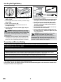
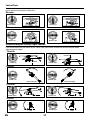
Control Tests
Test the controls prior to the fi rst fl ight to ensure the servos, linkages and parts operate correctly. Ensure the throttle is in
the low position when doing the control tests.
Understanding the Primary Flight Controls
If you are not familiar with the controls of your 120 S2, take a few minutes to familiarize yourself with them before
attempting your fi rst fl ight.
Throttle
Throttle down
Throttle up
Left Side View Left Side View
Descend
Climb
Elevator
Forward
Elevator down
Elevator up
Backward
Left Side View Left Side View
Rudder
Rudder left
Rudder right
Nose Yaws Right
Nose Yaws Left
Aileron
Aileron left
Left
Aileron right
Right
Rear ViewRear View

11
EN
Consult your local laws and ordinances before choosing a
location to fl y your aircraft.
We recommend fl ying your aircraft outside in calm winds
(3 MPH or less) or inside a large gymnasium. Always avoid
fl ying near houses, trees, wires and buildings. You should
also be careful to avoid fl ying in areas where there are many
people, such as busy parks, schoolyards or soccer fi elds.
It is best to fl y from a smooth fl at surface as this will allow
the model to slide without tipping over. Keep the helicopter
approximately 2 ft (600mm) above the ground. Keep the
tail pointed toward you during initial fl ights to keep the
control orientation consistent. Releasing the stick while in
Stability, low bank angle mode or Stability, high bank angle
mode will allow the helicopter to level itself and activating
the Panic Switch will level the helicopter quickly. If you
become disoriented, slowly lower the throttle stick to land
softly. During initial fl ights, only attempt hovering the model
in one spot and takeoff and landing.
Takeoff
Place the model onto a fl at, level surface free of obstacles
and walk back 30 feet (10 meters). Slowly increase the
throttle until the model is approximately 2 ft. (600mm)
off the ground and check the trim so the model fl ies as
desired. Once the trim is adjusted, begin fl ying the model.
Typical fl ight time for the included battery is approximately
6 minutes.
Hovering
Making small corrections on the transmitter, try to hold the
helicopter in one spot. If fl ying in calm winds, the model should
require almost no corrective inputs. After moving the cyclic
stick and returning it to center the model should level itself.
The model may continue to move due to inertia. Move the
cycle stick in the opposite direction to stop the movement.
Do not use the trims on the transmitter to eliminate drift.
If the helicopter does not hold a reasonable hover in calm
conditions, perform the Drift Calibration.
After you become comfortable hovering, you can progress
into fl ying the model to different locations, keeping the tail
pointed towards you at all times. You can also ascend and
descend using the throttle stick. Once you're comfortable
with these maneuvers, you can attempt fl ying with the tail
in different orientations. It is important to keep in mind that
the fl ight control inputs will rotate with the helicopter, so
always try to picture the control inputs relative to the nose
of the helicopter. For example, forward will always drop the
nose of the helicopter.
Low Voltage Cutoff (LVC)
LVC decreases the power to the motors when the battery
voltage gets low. When the motor power decreases and the
red LED on the ESC fl ashes, land the aircraft immediately
and recharge the fl ight battery.
LVC does not prevent the battery from over-discharge
during storage.
NOTICE: Repeated fl ying to LVC will damage the battery.
Landing
To land, slowly decrease the throttle while in a low-level
hover. After landing, disconnect and remove the battery
from the aircraft after use to prevent trickle discharge. Fully
charge your battery before storing it. During storage, make
sure the battery charge does not fall below 3V per cell.
Flight Modes
Stability, Low Bank Angle Mode (FM-0): The receiver
LED shows solid green. This fl ight mode allows a low
bank angle and slower fl ight speed. When the cyclic stick
is released the model will self-level.
Stability, High Bank Angle Mode (FM-1): The receiver
LED shows solid blue. This fl ight mode allows a high bank
angle and faster fl ight speed. When the cyclic stick is
released the model will self-level.
Agility Mode (FM-2): The receiver LED shows solid red.
The bank angle is not limited. When the cyclic stick is
released the model will not self-level.
Flying the 120 S2

12
EN
Post-Flight Inspection and Maintenance Checklist
Dri Calibration
Ball Links
Make sure the plastic ball link holds the control ball, but is not tight (binding) on the ball. When a link is
too loose on the ball, it can separate from the ball during fl ight and cause a crash. Replace worn ball links
before they fail.
Cleaning
Make sure the battery is not connected before cleaning. Remove dust and debris with a soft brush or a dry,
lint-free cloth.
Bearings Replace bearings when they become notchy (sticky in places when turning) or draggy.
Wiring Make sure the wiring does not contact moving parts. Replace damaged wiring and loose connectors.
Fasteners
Make sure there are no loose screws, other fasteners or connectors. Do not over-tighten metal screws in
plastic parts. Tighten screws so the parts are mated together, then turn the screw only 1/8th of a turn more.
Rotors
Make sure there is no damage to rotor blades and other parts which move at high speed. Damage to these
parts includes cracks, burrs, chips or scratches. Replace damaged parts before fl ying. Verify both main rotor
blades have the correct and equal tension in the blade grips. When the helicopter is held up sideways, the
main blades should support their own weight. When the helicopter is shaken lightly, the blades should fall.
Tail
Inspect the tail rotor for damage and replace if necessary. Inspect the tail boom for any damage and
replace if necessary.
Mechanics
Inspect the main frame and landing gear for damage and replace if necessary. Check the mainshaft for
vertical play and adjust the locking collar if necessary. Verify that the main gear mesh is correct and that no
tight spots exist in the 360 degree rotation. Inspect all wires for damage and replace as necessary.
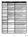
Troubleshooting Guide
Problem Possible Cause Solution
Helicopter is bound to a
Spektrum DXe but will not
respond to control input
The transmitter is in 9-channel
mode
Using the appropriate DXe programming cable and PC or
mobile app, either change the transmitter to 7-channel
mode or download the Blade 120 S2 model setup fi le to
your transmitter from www.spektrumrc.com
Helicopter will not respond
to throttle
Throttle too high and/or throttle trim
is too high
Disconnect the fl ight battery, place the throttle stick in the
lowest position and lower the throttle trim a few clicks.
Connect the fl ight battery and allow the model to initialize
Helicopter moved during
initialization
Disconnect the flight battery and re-initialize the helicopter
while keeping the helicopter from moving
The helicopter has been calibrated in the factory before
shipment, but it is possible that a crash will cause
mechanical distortion of the frame, resulting in a slight
drift in Stability mode. In this situation, please follow the
calibration procedure.
Before beginning the calibration procedure, fully charge the
fl ight battery and ensure the helicopter and transmitter are
bound properly, per the binding instructions.
To Calibrate the Blade 120 S2:
1. After initialization, move the transmitter sticks to the
bottom, outside corners, as shown in the illustration.
When the red
and blue LEDs
on the main
fl ight control
board glow
solid, calibration
mode is active.
2. Release the sticks.
3. Slowly advance the throttle to bring the helicopter into
a low hover. The red and blue LEDs fl ash continuosly
to indicate the calibration process has begun. Hold
the hover for approximately 15 seconds, using as little
control input as possible to keep the helicopter steady.
4. Land the helicopter by slowly lowering the throttle.
5. After landing, press the bind/panic button to complete
the calibration process. The LED will show solid blue.

13
EN
Problem Possible Cause Solution
Helicopter has reduced fl ight
time or is underpowered
Flight battery charge is low Completely recharge the fl ight battery
Flight battery is damaged
Replace the fl ight battery and follow the fl ight battery
instructions
Flight conditions might be too cold
Make sure the battery is warm (room temperature) before use
LED on receiver fl ashes
rapidly and aircraft will
not respond to transmitter
(during binding)
Transmitter too near aircraft during
binding process
Power off the transmitter. Move the transmitter a larger
distance from the aircraft. Disconnect and reconnect the
fl ight battery to the aircraft. Follow the binding instructions
Bind switch or button was not held
while transmitter was powered on
Power off transmitter and repeat bind process
Aircraft or transmitter is too close to
large metal object, wireless source
or another transmitter
Move aircraft and transmitter to another
location and attempt binding again
LED on the receiver fl ashes
rapidly and the helicopter
will not respond to the
transmitter (after binding)
Less than a 5-second wait between
fi rst powering on the transmitter
and connecting the fl ight battery to
the helicopter
Leave the transmitter powered on. Disconnect and
reconnect the fl ight battery to the helicopter
The helicopter is bound to
a different model memory
(ModelMatch
™
transmitters only)
Select the correct model memory on the transmitter.
Disconnect and reconnect the fl ight battery to the
helicopter
Flight battery or transmitter battery
charge is too low
Replace or recharge batteries
Aircraft or transmitter is too close to
large metal object, wireless source
or another transmitter
Move aircraft and transmitter to another
location and attempt connecting again
Helicopter vibrates or shakes
in fl ight
Damaged rotor blades, spindle,
blade grips, main gear teeth or
cracked main shaft.
Check main rotor blades, blade grips, main gear and main
shaft for cracks, chips or missing teeth. Replace damaged
parts. Replace bent spindle
Rotor head linkages not connected
correctly
Connect the rotor head linkages to the short ball links on
the swashplate
Model does not hold level/
Panic recovery does not
level. Random movements
in fl ight
Vibration
Verify the receiver is properly attached to the helicopter. Verify
that no wires are contacting the receiver. Inspect and balance
all rotating components. Verify the main shaft and tail rotor
adapter are not damaged or bent. Inspect mechanics for
broken or damaged parts and replace as necessary
Tail oscillation/wag or poor
performance
Loose tail boom, damaged tail rotor,
loose bolts, vibration
Verify that the boom is tight and completely inserted into the
frame. Inspect the tail rotor for damage. Verify the tail motor
mount is tight. Replace any damaged or worn components
Drift in calm winds
Vibration, damaged linkage,
damaged servo
Under normal operation the transmitter trims should
not require adjustment and the center positions are
memorized during initialization. If you fi nd that trim
adjustments are necessary after take off, verify the
balance of all rotating components, ensure the linkages
are not damaged and make sure the servos are in proper
working condition. Perform the Drift Calibration procedure
Drift in wind Normal
The model will drift with the wind but should remain level
in fl ight. Simply hold the cyclic stick in the necessary
position to keep the model stationary. The model must
lean into the wind to remain stationary, if the model
remains level then it will drift with the wind
Severe vibration Rotating component out of balance
Check the main shaft, tail rotor, main rotor blades, main
frame and adapter for damage, replace as necessary.
Vibration must be minimized for Panic Recovery and
Return to Level functions to work properly

14
EN
1
10
23
3
4
13
26
5
7
8
20
9
25
6
15
16
12
17
24
18
18
19
11 15
22
22
14
14
2
21
21
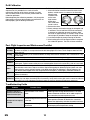
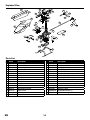
Exploded View
Parts List
Part # Description
BLH1100 120 S2 RTF
BLH1180 120 S2 BNF
1
SPMSH2029L
Linear Long, 35mm lead
2
SPMSH2030L
Linear Long, 60mm lead
3 BLH1101 Main Control Board
4 BLH4102 Tail Boom Set
5 BLH4103 Main Motor
6 BLH4104 Main Frame
7 BLH4105 Main Shaft w/hardware
8 BLH4106 Swashplate
9 BLH1102 Canopy
10 BLH1103 Tail Fin
11 BLH4111 Main Blades w/screws
12 BLH4112 Battery Frame
13 BLH3117 Tail Rotor
14 BLH3705 Canopy Mounts
Part # Description
15 BLH3115 Rotor Head Linkage
16 BLH3106 Main gear
17 BLH3709 Landing gear Set
18 BLH3114
Main Blade grips with Hardware and screws
19 BLH3108 Servo Pushrod Set with Ball link (2)
20 BLH3112 Main Rotor Hub with Hardware
21 BLH3128 Main Shaft Bearing 4 x 7 x 2
22 BLH3113 Feathering Spindle w/O-rings and bushings
23 BLH4113 Tail Motor
24
EFLB5001S25
1S, 500 mAh, 25C LiPo Battery, JST
25 BLH3121 Canopy Mounting Grommets (8)
26 BLH3125 Tail Motor Protective Sleeve
BLH4109 Screw set: 120 S
SPMRMLP6 MLP6DSM SAFE 6ch Tx
EFLC1010 1S USB LiPo Charger, 500mA

15
EN
Limited Warranty
What this Warranty Covers
Horizon Hobby, LLC, (Horizon) warrants to the original purchaser
that the product purchased (the “Product”) will be free from
defects in materials and workmanship at the date of purchase.
What is Not Covered
This warranty is not transferable and does not cover (i) cosmetic
damage, (ii) damage due to acts of God, accident, misuse,
abuse, negligence, commercial use, or due to improper use,
installation, operation or maintenance, (iii) modifi cation of or to
any part of the Product, (iv) attempted service by anyone other
than a Horizon Hobby authorized service center, (v) Product not
purchased from an authorized Horizon dealer, (vi) Product not
compliant with applicable technical regulations, or (vii) use that
violates any applicable laws, rules, or regulations.
OTHER THAN THE EXPRESS WARRANTY ABOVE, HORIZON
MAKES NO OTHER WARRANTY OR REPRESENTATION, AND
HEREBY DISCLAIMS ANY AND ALL IMPLIED WARRANTIES,
INCLUDING, WITHOUT LIMITATION, THE IMPLIED WARRANTIES
OF NON-INFRINGEMENT, MERCHANTABILITY AND FITNESS FOR
A PARTICULAR PURPOSE. THE PURCHASER ACKNOWLEDGES
THAT THEY ALONE HAVE DETERMINED THAT THE PRODUCT
WILL SUITABLY MEET THE REQUIREMENTS OF THE
PURCHASER’S INTENDED USE.
Purchaser’s Remedy
Horizon’s sole obligation and purchaser’s sole and exclusive
remedy shall be that Horizon will, at its option, either (i)
service, or (ii) replace, any Product determined by Horizon to
be defective. Horizon reserves the right to inspect any and all
Product(s) involved in a warranty claim. Service or replacement
decisions are at the sole discretion of Horizon. Proof of purchase
is required for all warranty claims. SERVICE OR REPLACEMENT
AS PROVIDED UNDER THIS WARRANTY IS THE PURCHASER’S
SOLE AND EXCLUSIVE REMEDY.
Limitation of Liability
HORIZON SHALL NOT BE LIABLE FOR SPECIAL, INDIRECT,
INCIDENTAL OR CONSEQUENTIAL DAMAGES, LOSS OF
PROFITS OR PRODUCTION OR COMMERCIAL LOSS IN ANY
WAY, REGARDLESS OF WHETHER SUCH CLAIM IS BASED IN
CONTRACT, WARRANTY, TORT, NEGLIGENCE, STRICT LIABILITY
OR ANY OTHER THEORY OF LIABILITY, EVEN IF HORIZON HAS
BEEN ADVISED OF THE POSSIBILITY OF SUCH DAMAGES.
Further, in no event shall the liability of Horizon exceed the
individual price of the Product on which liability is asserted.
As Horizon has no control over use, setup, fi nal assembly,
modifi cation or misuse, no liability shall be assumed nor
accepted for any resulting damage or injury. By the act of use,
setup or assembly, the user accepts all resulting liability. If you
as the purchaser or user are not prepared to accept the liability
associated with the use of the Product, purchaser is advised to
return the Product immediately in new and unused condition to
the place of purchase.
Law
These terms are governed by Illinois law (without regard to
confl ict of law principals). This warranty gives you specifi c legal
rights, and you may also have other rights which vary from
state to state. Horizon reserves the right to change or modify
this warranty at any time without notice.
WARRANTY SERVICES
Questions, Assistance, and Services
Your local hobby store and/or place of purchase cannot
provide warranty support or service. Once assembly, setup or
use of the Product has been started, you must contact your
local distributor or Horizon directly. This will enable Horizon to
better answer your questions and service you in the event that
you may need any assistance. For questions or assistance,
please visit our website at www.horizonhobby.com, submit a
Product Support Inquiry, or call the toll free telephone number
referenced in the Warranty and Service Contact Information
section to speak with a Product Support representative.
Inspection or Services
If this Product needs to be inspected or serviced and is
compliant in the country you live and use the Product in,
please use the Horizon Online Service Request submission
process found on our website or call Horizon to obtain a Return
Merchandise Authorization (RMA) number. Pack the Product
securely using a shipping carton. Please note that original boxes
may be included, but are not designed to withstand the rigors
of shipping without additional protection. Ship via a carrier that
provides tracking and insurance for lost or damaged parcels, as
Horizon is not responsible for merchandise until it arrives and is
accepted at our facility. An Online Service Request is available
at http://www.horizonhobby.com/content/service-center_
render-service-center. If you do not have internet access, please
contact Horizon Product Support to obtain a RMA number along
with instructions for submitting your product for service. When
calling Horizon, you will be asked to provide your complete
name, street address, email address and phone number where
you can be reached during business hours. When sending
product into Horizon, please include your RMA number, a list of
the included items, and a brief summary of the problem. A copy
of your original sales receipt must be included for warranty
consideration. Be sure your name, address, and RMA number
are clearly written on the outside of the shipping carton.
NOTICE: Do not ship Li-Po batteries to Horizon. If you
have any issue with a Li-Po battery, please contact the
appropriate Horizon Product Support offi ce.
Warranty Requirements
For Warranty consideration, you must include your original sales
receipt verifying the proof-of-purchase date. Provided warranty
conditions have been met, your Product will be serviced or
replaced free of charge. Service or replacement decisions are
at the sole discretion of Horizon.
Non-Warranty Service
Should your service not be covered by warranty, service will be
completed and payment will be required without notifi cation
or estimate of the expense unless the expense exceeds
50% of the retail purchase cost. By submitting the item for
service you are agreeing to payment of the service without
notifi cation. Service estimates are available upon request. You
must include this request with your item submitted for service.
Non-warranty service estimates will be billed a minimum of
½ hour of labor. In addition you will be billed for return freight.
Horizon accepts money orders and cashier’s checks, as well
as Visa, MasterCard, American Express, and Discover cards.
By submitting any item to Horizon for service, you are agreeing
to Horizon’s Terms and Conditions found on our website http://
www.horizonhobby.com/content/service-center_render-
service-center.
ATTENTION: Horizon service is limited to Product
compliant in the country of use and ownership. If received,
a non-compliant Product will not be serviced. Further, the
sender will be responsible for arranging return shipment
of the un-serviced Product, through a carrier of the
sender’s choice and at the sender’s expense. Horizon will
hold non-compliant Product for a period of 60 days from
notifi cation, after which it will be discarded.
10/15

16
EN
FCC Information
Contains FCC ID: BRWWACO1T
This device complies with part 15 of the FCC rules. Operation
is subject to the following two conditions: (1) This device
may not cause harmful interference, and (2) this device must
accept any interference received, including interference that
may cause undesired operation.
CAUTION: Changes or modifi cations not expressly
approved by the party responsible for compliance
could void the user’s authority to operate the equipment.
This product contains a radio transmitter with wireless
technology which has been tested and found to be compliant
with the applicable regulations governing a radio transmitter
in the 2.400GHz to 2.4835GHz frequency range.
Supplier’s Declaration of Conformity
Blade 120 S2 RTF/BNF (BLH1100 / BLH1180)
This device complies with part 15 of the FCC Rules.
Operation is subject to the following two
conditions: (1) This device may not cause harmful
interference, and (2) this device must accept any
interference received, including interference that may cause
undesired operation.
CAUTION: Changes or modifi cations not expressly
approved by the party responsible for compliance
could void the user’s authority to operate the equipment.
NOTE: This equipment has been tested and found to comply
with the limits for a Class B digital device, pursuant to part
15 of the FCC Rules. These limits are designed to provide
reasonable protection against harmful interference in a
residential installation. This equipment generates, uses and
can radiate radio frequency energy and, if not installed and
used in accordance with the instructions, may cause harmful
interference to radio communications. However, there
is no guarantee that interference will not occur in a
particular installation. If this equipment does cause harmful
interference to radio or television reception, which can be
determined by turning the equipment off and on, the user is
encouraged to try to correct the interference by one or more
of the following measures:
• Reorient or relocate the receiving antenna.
• Increase the separation between the equipment and
receiver.
• Connect the equipment into an outlet on a circuit
different from that to which the receiver is connected.
• Consult the dealer or an experienced radio/TV technician
for help.
Horizon Hobby, LLC
2904 Research Rd.
Champaign, IL 61822
Email: [email protected]
Web: HorizonHobby.com
Warranty and Service Contact Information
Country of Purchase Horizon Hobby Contact Information Address
United States of
America
Horizon Service Center
(Repairs and Repair Requests)
servicecenter.horizonhobby.com/
RequestForm/
2904 Research Rd
Champaign, Illinois, 61822 USA
Horizon Product Support
(Product Technical Assistance)
productsupport@horizonhobby.com
877-504-0233
Sales
websales@horizonhobby.com
800-338-4639
European Union
Horizon Technischer Service service@horizonhobby.eu
Hanskampring 9
D 22885 Barsbüttel, Germany
Sales: Horizon Hobby GmbH +49 (0) 4121 2655 100
IC Information
Contains IC: 6157A-WACO1T
This device complies with Industry Canada license-exempt
RSS standard(s). Operation is subject to the following two
conditions:
(1) this device may not cause interference, and (2) this
device must accept any interference, including interference
that may cause undesired operation of the device.

17
EN
Compliance Information for the European Union
EU Compliance Statement:
Blade 120 S2 RTF (BLH1100)
Horizon Hobby, LLC hereby declares that this
product is in compliance with the essential
requirements and other relevant provisions of the RED,
EMC, and LVD Directives.
Blade 120 S2 BNF (BLH1180)
Horizon Hobby, LLC hereby declares that this product is
in compliance with the essential requirements and other
relevant provisions of the RED and EMC Directives.
A copy of the EU Declaration of Conformity is available online at:
http://www.horizonhobby.com/content/support-render-compliance.
Instructions for disposal of WEEE by users in the European Union
This product must not be disposed of with
other waste. Instead, it is the user’s
responsibility to dispose of their waste
equipment by handing it over to a designated
collections point for the recycling of waste
electrical and electronic equipment. The
separate collection
and recycling of your waste equipment at the time of disposal
will help to conserve natural resources and make sure that it
is recycled in a manner that protects human health and the
environment. For more information about where you can drop
off your waste equipment for recycling, please contact your
local city offi ce, your household waste disposal service or
where you purchased the product.

©2020 Horizon Hobby, LLC.
Blade, the Blade logo, E-Flite, BNF, the BNF logo, DSM, DSM2, DSMX, SAFE, the SAFE logo, Spektrum AirWare
and ModelMatch are trademarks or registered trademarks of Horizon Hobby, LLC.
The Spektrum trademark is used with permission of Bachmann Industries, Inc.
All other trademarks, service marks and logos are property of their respective owners.
US 9,930,567. US 10,419,970. Other patents pending.
Created 3/20 61256 BLH1100, BLH1180
-
 1
1
-
 2
2
-
 3
3
-
 4
4
-
 5
5
-
 6
6
-
 7
7
-
 8
8
-
 9
9
-
 10
10
-
 11
11
-
 12
12
-
 13
13
-
 14
14
-
 15
15
-
 16
16
-
 17
17
-
 18
18


Blade BLH1180 Owner's manual
- Category
- Remote controlled toys
- Type
- Owner's manual
- This manual is also suitable for
Ask a question and I''ll find the answer in the document
Finding information in a document is now easier with AI
Related papers
Other documents
-
E-flite 120 SR User manual
-
Dowellin Toys Factory DRW533VPBU User manual
-
ADURO PW-10KSHN User manual
-
E-flite Blade SR User manual
-
Sharper Image Unbreakable Helicopter Owner's manual
-
Spektrum AR6410NBL DSMX 6Ch Ultra Micro Rx BL-ESC No Servos User guide
-
Spektrum SPMXC1060 Owner's manual
-
Xtreme XBB8-0146-BLK User manual
-
-
Proximus PHOENIX - P16-41461 User manual