Blade BLH2900 User manual

Category
Remote controlled toys
Type
User manual

The Blade BLH2900 is a compact and lightweight helicopter that is perfect for both indoor and outdoor flying. With its powerful motor and durable construction, the BLH2900 is capable of performing a variety of aerobatic maneuvers, including flips, rolls, and loops. The BLH2900 also features a number of safety features, such as a self-leveling function and a low-battery warning system, making it a great choice for both experienced and beginner pilots.

The Blade BLH2900 is a compact and lightweight helicopter that is perfect for both indoor and outdoor flying. With its powerful motor and durable construction, the BLH2900 is capable of performing a variety of aerobatic maneuvers, including flips, rolls, and loops. The BLH2900 also features a number of safety features, such as a self-leveling function and a low-battery warning system, making it a great choice for both experienced and beginner pilots.

Instruction Manual
Bedienungsanleitung
Manuel d’utilisation
Manuale di Istruzioni
RTF
2
EN
WARNING: Read the ENTIRE instruction manual to become familiar with the
features of the product before operating. Failure to operate the product cor-
rectly can result in damage to the product, personal property and cause serious injury.
This is a sophisticated hobby product. It must be operated with caution and common
sense and requires some basic mechanical ability. Failure to operate this Product
in a safe and responsible manner could result in injury or damage to the product or
other property. This product is not intended for use by children without direct adult
supervision. Do not use with incompatible components or alter this product in any
way outside of the instructions provided by Horizon Hobby, LLC. This manual contains
instructions for safety, operation and maintenance. It is essential to read and follow
all the instructions and warnings in the manual, prior to assembly, setup or use, in
order to operate correctly and avoid damage or serious injury.
The following terms are used throughout the product literature to indicate various
levels of potential harm when operating this product:
NOTICE: Procedures, which if not properly followed, create a possibility of physical
property damage AND a little or no possibility of injury.
CAUTION: Procedures, which if not properly followed, create the probability of
physical property damage AND a possibility of serious injury.
WARNING: Procedures, which if not properly followed, create the probability of
property damage, collateral damage, and serious injury OR create a high probability
of superfi cial injury.
NOTICE
All instructions, warranties and other collateral documents are subject to change
at the sole discretion of Horizon Hobby, LLC. For up-to-date product literature, visit
horizonhobby.com and click on the support tab for this product.
Meaning of Special Language
Age Recommendation: Not for children under 14 years. This is not a toy.
WARNING AGAINST COUNTERFEIT PRODUCTS: If you ever need to replace
your Spektrum receiver found in a Horizon Hobby product, always purchase
from Horizon Hobby, LLC or a Horizon Hobby authorized dealer to ensure authentic
high-quality Spektrum product. Horizon Hobby, LLC disclaims all support and warranty
with regards, but not limited to, compatibility and performance of counterfeit products or
products claiming compatibility with DSM or Spektrum technology.
3
EN
Always keep a safe distance in all directions around your model to avoid collisions
or injury. This model is controlled by a radio signal subject to interference from many
sources outside your control. Interference can cause momentary loss of control.
• Always operate your model in open spaces away from full-size vehicles, traffi c and people.
Always carefully follow the directions and warnings for this and any optional
support equipment (chargers, rechargeable battery packs, etc.).
• Always keep all chemicals, small parts and anything electrical out of the reach of children.
Always avoid water exposure to all equipment not specifi cally designed
and protected for this purpose. Moisture causes damage to electronics.
Never place any portion of the model in your mouth as it could cause serious injury
or even death.
Never operate your model with low transmitter batteries.
Always keep aircraft in sight and under control.
Always move the throttle fully down at rotor strike.
Always use fully charged batteries.
Always keep transmitter powered on while aircraft is powered.
Always remove batteries before disassembly.
Always keep moving parts clean.
Always keep parts dry.
Always let parts cool after use before touching.
Always remove batteries after use.
Never operate aircraft with damaged wiring.
Never touch moving parts.
Safety Precautions and Warnings
4
EN
Table of Contents
Box Contents .........................................................................................................5
First Flight Preparation ...........................................................................................6
Flying Checklist ......................................................................................................6
Charging Warnings .................................................................................................6
Charge the Flight Battery ........................................................................................7
Installing the Transmitter Batteries (RTF) ..................................................................7
Transmitter Setup (BNF) ..........................................................................................8
Installing the Flight Battery ...................................................................................13
Transmitter and Receiver Binding ..........................................................................14
RTF Transmitter Controls .....................................................................................15
Control Tests ........................................................................................................16
Understanding the Primary Flight Controls .............................................................16
Flying the mSR S .................................................................................................18
Drift Calibration ....................................................................................................19
Post-Flight Inspection and Maintenance Checklist ..................................................20
Troubleshooting Guide ..........................................................................................20
Exploded View......................................................................................................23
Parts List .............................................................................................................23
Optional Parts ......................................................................................................24
Limited Warranty ..................................................................................................24
Warranty and Service Contact Information .............................................................26
FCC Information ...................................................................................................27
IC Information ......................................................................................................27
Compliance Information for the European Union .....................................................28
5
EN
Box Contents
Blade mSR S
150mAh 1S 3.7V 45C Li-Po Battery
1S 300mA Li-Po USB Charger
MLP4DSM Transmitter (RTF Only)
4 AA Batteries (RTF Only)
Specifications
Length
8.00 in (205mm)
Height
3.30 in (83mm)
Main Rotor Diameter
7.08 in (180mm)
Tail Rotor Diameter
1.57 in (40mm)
Flying Weight
1.10 oz (31 g)
To receive product updates, special offers and more,
register your product at www.bladehelis.com.
6
EN
Charging Warnings
First Flight Preparation
Remove and inspect contents
Begin charging the fl ight battery
Install the batteries in the transmitter (RTF only)
Program your computer transmitter (BNF only)
Install the fl ight battery in the helicopter (once it has been fully charged)
Bind your transmitter (BNF only)
Familiarize yourself with the controls
Find a suitable area for fl ying
Flying Checklist
Always turn the transmitter on fi rst
Plug the fl ight battery into the lead from the ESC
Allow the receiver and ESC to initialize and arm properly
Fly the model
Land the model
Unplug the fl ight battery from the ESC
Always turn the transmitter off last
CAUTION: All instructions and warnings must be followed exactly. Mishandling of
Li-Po batteries can result in a fi re, personal injury and/or property damage.
NEVER LEAVE CHARGING BATTERIES UNATTENDED.
NEVER CHARGE BATTERIES OVERNIGHT.
By handling, charging or using the included Li-Po battery, you assume all risks associated
with lithium batteries.
If at any time the battery begins to balloon or swell, discontinue use immediately. If charging
or discharging, discontinue and disconnect. Continuing to use, charge or discharge a battery
that is ballooning or swelling can result in fi re.
Always store the battery at room temperature in a dry area for best results.
Always transport or temporarily store the battery in a temperature range of 40–120º F (549° C).
Do not store battery or model in a car or direct sunlight. If stored in a hot car, the battery can
be damaged or even catch fi re.
Always charge batteries away from fl ammable materials.
Always inspect the battery before charging
Always disconnect the battery after charging, and let the charger cool between charges.
Always constantly monitor the temperature of the battery pack while charging.
ONLY USE A CHARGER SPECIFICALLY DESIGNED TO CHARGE LI-PO BATTERIES. Failure to
charge the battery with a compatible charger may cause a fi re resulting in personal injury
and/or property damage.
Never discharge Li-Po cells to below 3V under load.
Never cover warning labels with hook and loop strips.
Never charge batteries outside recommended levels.
Never charge damaged batteries.
Never attempt to dismantle or alter the charger.
Never allow minors to charge battery packs.
Never charge batteries in extremely hot or cold places (recommended between 40–120° F
or (549° C) or place in direct sunlight.
7
EN
Installing the Transmitter Batteries (RTF)
Replace the transmitter batteries when the transmitter beeps continuously.
Charge the Flight Battery
NOTICE: Inspect the battery to make sure it is not damaged e.g., swollen, bent, broken
or punctured. Only charge batteries that are cool to the touch and are not damaged.
Insert the charger into a USB port.
Connect the battery to the charger.
CHARGING (Solid Red LED)
MAX CHARGE (LED OFF )
Disconnect the fl ight battery from the charger immediately upon completion of charging.
CAUTION: Only use chargers specifi cally designed to charge the included Li-Po
battery. Failure to do so could result in fi re, causing injury or property damage.
CAUTION: Never exceed the recommended charge rate.
CAUTION: Once charging is complete, immediately remove the battery.
Never leave a battery connected to the charger.
USB Li-Po
Charger
EFLC1008
SOLID RED LED
Charging
DC Input:5.0V 350mA
DC Output:4.2V 300mA
LED OFF
Charge
Complete
8
EN
Transmitter Setup (BNF)
Program your transmitter before attempting to bind or fl y the helicopter. Transmitter
programming values are shown below for the Spektrum DX6i, DX7s, DX6, DX7, DX8,
DX9, DX18 and DX20.
The fi les for models using Spektrum
transmitters with AirWare
software are also
available for download online at www.spektrumrc.com.
Your helicopter is also compatible with Spektrum DXe radios with software version 1.3 or
higher. Use the directions below to reverse channel 6, or use the appropriate program-
ming cable and the PC or mobile app to program the DXe. We recommend downloading
the Blade mSR S DXe model setup available at www.spektrumrc.com.
If you are programming your DXe using the PC or mobile app, make sure the
"Transmitter Channels" value is set to the default of 7. If for any reason this value is
changed to 9, the mSR S will bind to the DXe, but will not respond to control inputs.
If your DXe was included in another Blade Ready To Fly (RTF) helicopter, the transmitter
software will have to be updated using the appropriate programming cable and either the
PC or mobile app available at www.spektrumrc.com. Please note, the switch confi gura-
tion used for DXe transmitters included with the Blade 230 S RTF and Micro AH-64
Apache RTF varies from the standard DXe layout.
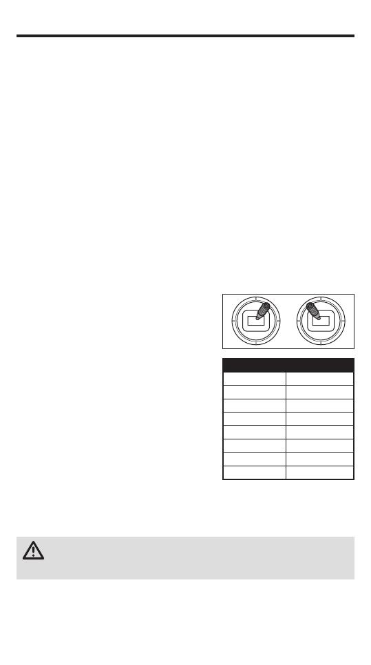
To use the DXe transmitter with the Blade mSR S, channel 6 must be reversed.
To reverse channel 6:
1. While powering on the DXe, hold the left and
right sticks in the top-inside corners as shown.
2. Re-center the sticks after the transmitter
beeps. The LED will fl ash slowly.
3. To select a channel to reverse, move the
right stick to the left or right and allow it to
re-center. Move the stick to the right to select
the next channel. Move the stick to the left
to select the previous channel. The LED will
ash rapidly corresponding to the channel
selected, as shown in the table. Select
channel 6.
4. To reverse the selected channel, move the
right stick up or down. The LED will change
color to indicate the new channel direction.
The LED will fl ash Orange to indicate the channel is normal.
The LED will fl ash Red to indicate the channel is reversed.
5. To store the changes, power off the DXe.
CAUTION: During the subsequent power up, always verify the throttle
direction is correct and keep clear of the motor and rotor blades. Failure to
do so may result in injury or damage to the product.
After reversing channel 6, bind the transmitter and helicopter normally.
Flight modes are controlled by the Flight Mode switch.
Panic Mode is controlled by the Bind/Panic/Trainer button.
DXe
LED Flashes Channel
1 1-Throttle
2 2-Aileron
3 3-Elevator
4 4-Rudder
5 5-Flight Mode
6 6-Panic
7 7-Flaps
8 8-Aux Channel
9
EN
D/R & Expo
Chan Sw Pos D/R Expo*
AILE
0 100 INH
1 75 INH
ELEV
0 100 INH
1 75 INH
RUDD
0 100 INH
1 75 INH
Timer
Down Timer 5:00
Switch THR CUT
ADJUST LIST
SETUP LIST
DX6i
TRAVEL ADJ
Channel Travel
THRO 100/100
AILE 100/100
ELEV 100/100
RUDD 100/100
GEAR 100/100
PITC 100/100
REVERSE
Channel Direction
THRO N
AILE N
ELEV N
RUDD N
GEAR R
FLAP N
Modulation Type
AUTO DSMX-ENABLE
Model Type
Acro
D/R COMBI
D/R SW AILE
Flight Mode Operation
Gear Sw: Pos 0, Elev D/R Sw: 0 or 1 = Stability, Low-Angle Mode
Gear Sw: Pos 1, Elev D/R Sw: 0 = Stability, High-Angle Mode
Gear Sw: Pos 1, Elev D/R Sw: 1 = Agility Mode
Mixing
MIX 1 ACT
GEAR > GEAR ACT
RATE D 0% U –100%
SW GEAR TRIM – INH
MIX 2 ACT
GEAR > GEAR ACT
RATE D 0% U +100%
SW ELE D/R TRIM – INH
FLAPS
FLAP ELEV
NORM 100 0
LAND 100 0
* Use of "Expo" is not necessary for successful fl ight of the mSR S. The pilot may
adjust this setting to tailor the sensitivity of the helicopter around neutral if desired.
Panic Mode Operation
Gy ro Switch:
Pos 0 = Panic Mode Off
Pos 1 = Panic Mode On
Once bound, the LED in the helicopter should glow blue for fl ight modes 0 and 1
(Stability, Low-Angle and High-Angle Modes), and glow red for fl ight mode 2 (Agility mode).
If the LED glows blue in all three fl ight modes, channel 6 has not been reversed correctly.
Use the directions above to reverse channel 6.
10
EN
Servo Setup
FUNCTION LIST
SYSTEM SETUP
DX7s
Throttle Cut
Switch Mix 1
D/R & Expo
Chan
Switch Pos
(FLAP)
D/R
Expo*
AILE
0 100/100 0
1 100/100 0
2 75/75 0
ELEV
0 100/100 0
1 100/100 0
2 75/75 0
D/R & Expo
Chan
Switch Pos
(FLAP)
D/R
Expo*
RUDD
0 100/100 0
1 100/100 0
2 75/75 0
Timer
Mode Count Down
Time 5:00 Tone
Start Throttle Out
Pos 25%
Chan Travel Reverse
THR 100/100 Normal
AIL 100/100 Normal
ELE 100/100 Normal
RUD 100/100 Normal
Chan Travel Reverse
GER 100/100 Normal
AX1 100/100 Reverse
AX2 100/100 Normal
SW Select
Trainer Aux 1
Flap Gear
All Others INH
* Use of "Expo" is not necessary for successful fl ight of the mSR S. The pilot may
adjust this setting to tailor the sensitivity of the helicopter around neutral if desired.
Flight Mode Operation
FLAP Sw: Pos 0 = Stability, Low-Angle Mode
Pos 1 = Stability, High-Angle Mode
Pos 2 = Agility Mode
Model Type
Acro
Panic Mode Operation
Tr ainer/Bind Button:
Pressed = Panic Mode On
Released = Panic Mode Off
11
EN
Servo Setup
FUNCTION LIST
SYSTEM SETUP
DX8
Throttle Cut
Switch Mix 1
D/R & Expo
Chan
Switch Pos (AIL
D/R)
D/R
Expo*
AILE
0 100/100 0
1 100/100 0
2 75/75 0
ELEV
0 100/100 0
1 100/100 0
2 75/75 0
D/R & Expo
Chan
Switch Pos (AIL
D/R)
D/R
Expo*
RUDD
0 100/100 0
1 100/100 0
2 75/75 0
Timer
Mode Count Down
Time 5:00 Tone
Start Throttle Out
Pos 25%
Chan Travel Reverse
THR 100/100 Normal
AIL 100/100 Normal
ELE 100/100 Normal
RUD 100/100 Normal
Chan Travel Reverse
GER 100/100 Normal
AX1 100/100 Reverse
AX2 100/100 Normal
SW Select
Trainer Aux 1
F Mode Gear
All Others INH
* Use of "Expo" is not necessary for successful fl ight of the mSR S. The pilot may
adjust this setting to tailor the sensitivity of the helicopter around neutral if desired.
Flight Mode Operation
F MODE Sw: Pos 0 = Stability, Low-Angle Mode
Pos 1 = Stability, High-Angle Mode
Pos 2 = Agility Mode
Model Type
Acro
Panic Mode Operation
Tr ainer/Bind Button:
Pressed = Panic Mode On
Released = Panic Mode Off
12
EN
Throttle Cut
Position –130
Switch Switch H
0
1
Chan Travel Reverse
THR 100/100 Normal
AIL 100/100 Normal
ELE 100/100 Normal
RUD 100/100 Normal
GER 100/100 Normal
Chan Travel Reverse
AX1 100/100 Reverse
AX2 100/100 Normal
AX3 100/100 Normal
AX4 100/100 Normal
Servo Setup
FUNCTION LIST
DX6, DX6e, DX7 (Gen 2), DX8 (Gen 2), DX9, DX18, DX20
Timer
Mode Count Down
Time 5:00
Start Throttle Out
Over 25%
One Time Inhibit
D/R & Expo
Chan
Switch (F) Pos
D/R Expo*DX6
DX7, 9,
18
AILE
0 0 100/100 0
1 100/100 0
1 2 75/75 0
ELEV
0 0 100/100 0
1 100/100 0
1 2 75/75 0
RUDD
0 0 100/100 0
1 100/100 0
1 2 75/75 0
* Use of "Expo" is not necessary for successful fl ight of the mSR S. The pilot may
adjust this setting to tailor the sensitivity of the helicopter around neutral if desired.
Flight Mode Operation
Sw B: Pos 0 = Stability, Low-Angle Mode
Pos 1 = Stability, High-Angle Mode
Pos 2 = Agility Mode
Model Type
Acro
F-Mode Setup
Switch 1 Switch B
Switch 2 Inhibit
Channel Assign
Channel Input
1 Throttle N/A
2 Aileron N/A
3 Elevator N/A
4 Rudder N/A
5 Gear B
6 AUX 1 I
SYSTEM SETUP
Panic Mode Operation
Bi nd / I Button:
Pressed = Panic Mode On
Released = Panic Mode Off
13
EN
1. Lower the throttle stick to the lowest position (A) and center all trims.
2. Set the Flight Mode Switch to Stability Mode (FM0)
3. Power ON the transmitter (B).
4. Slide the fl ight battery fully into the mount of the helicopter frame (C).
5. Connect the power lead to the battery (D), noting the correct polarity.
CAUTION: Connecting the battery to the control board with reversed polarity
will cause damage to the control board, the battery or both. Damage caused
by incorrectly connecting the battery is not covered under warranty.
6. Place the helicopter on a fl at surface and leave it still until the red LED changes to
blue and glows solid, indicating initialization is complete.
If the LED on the control board fl ashes rapidly, proceed to the Transmitter and
Receiver Binding section to bind the helicopter and transmitter.
NOTICE: Do not allow the helicopter to move until the LED on the control board is
solid blue.
If you experience issues during initialization, refer to the Troubleshooting Guide at the
back of the manual.
CAUTION: Always disconnect the Li-Po battery from the aircraft when not
ying to avoid over-discharging the battery. Batteries discharged to a voltage
lower than the lowest approved voltage may become damaged, resulting in loss of
performance and potential fi re when batteries are charged.
Installing the Flight Battery
A B
C
D
14
EN
Transmitter and Receiver Binding
MLP4DSM Binding Procedure (RTF)
1. Disconnect the fl ight battery from the helicopter.
2. Center all trims on your transmitter.
3. Power off the transmitter and move the throttle stick to the low/off position.
4. Connect the fl ight battery to the control board. The control board LED fl ashes,
indicating it is in bind mode.
5. When the Blue LED is fl ashing, push in and hold down the left stick while powering on the
transmitter (you will hear a ‘click’).
6. Release the left stick. The transmitter will beep and the power LED will blink.
7. The helicopter is bound when the LED on the control board is solid blue (not blinking).
8. Disconnect the fl ight battery and power the transmitter off.
If you encounter problems, obey binding instructions and refer to the troubleshooting guide for
other instructions. If needed, contact the appropriate Horizon Product Support offi ce. For a list
of compatible DSM
®
transmitters, please visit www.bindnfl y.com.
Your RTF transmitter comes prebound to the model. If you need to re-bind,
follow the directions below.
To bind or re-bind your helicopter to your chosen transmitter, follow the directions below.
General Binding Procedure (BNF)
1. Disconnect the fl ight battery from the helicopter.
2. Refer the Transmitter Setup Table to correctly setup your transmitter.
3. Lower the throttle stick to the lowest position and center all trims on your transmitter.
4. Power off the transmitter and move all switches to the 0 position. Move the throttle
to the low/off position.
5. Connect the fl ight battery to the control board. The control board LED fl ashes,
indicating it is in bind mode.
6. Put the transmitter into bind mode while powering on the transmitter.
7. Release the bind button/switch after 2–3 seconds. The helicopter is bound when
the LED on the control board is solid blue (not blinking).
8. Disconnect the fl ight battery and power the transmitter off.
CAUTION: When using a Futaba
®
transmitter with a Spektrum
DSM2
®
module, you must reverse the throttle channel and re-bind. Refer to your
Spektrum module manual for binding and failsafe instructions. Refer to your Futaba
transmitter manual for instructions on reversing the throttle channel.
15
EN
RTF Transmitter Controls
ABCDE F
Mode
1
Aileron (Left/Right)
Throttle (Up/Down)
Throttle
Trim
Aileron
Trim
Rudder
Trim
Elevator
Trim
Rudder (Left/Right)
Elevator (Up/Down)
Mode
2
Aileron (Left/Right)
Elevator (Up/Down)
Elevator
Trim
Aileron
Trim
Rudder
Trim
Throttle
Trim
Rudder (Left/Right)
Throttle (Up/Down)
Flight Mode
Bind / Panic Mode
D
E
F
LED indicator
C
B
A
On/Off Switch
When pressed down, trim buttons make a sound that increases or decreases in pitch at
each pressing. The middle or neutral trim position is heard as a middle tone in the pitch
range of the sounds. The end of the control range is sounded by a series of beeps.
Flight Mode Selection
The fl ight mode can be changed by pressing and releasing the right control stick. The
LED on the transmitter will show solid for Stability, low bank angle mode (default) and
ashing for Agility mode.
g
16
EN
Backward Cyclic
Forward Cyclic
Left Side View
Left Cyclic
Right Cyclic
Rear View
Control Tests
Test the controls prior to the fi rst fl ight to ensure the servos, linkages and parts operate
correctly. Ensure the throttle is in the low position when doing the control tests.
Understanding the Primary Flight Controls
If you are not familiar with the controls of your mSR S, take a few minutes
to familiarize yourself with them before attempting your fi rst fl ight.
Throttle
Throttle up
Left Side View
Elevator (Forward and Backward Cyclic)
Aileron (Le and Right Cyclic)
Climb
17
EN
Forward Cyclic
Throttle down
Left Side View
Forward
Backward
Backward Cyclic
Top View
Rudder left
Rudder right
Nose Yaws Right
Nose Yaws Left
Descend
Rudder (Yaw)
Elevator (Forward and Backward Cyclic)
18
EN
Aileron (Le and Right Cyclic)
Left Cyclic
Left
Rear View
Right Cyclic
Right
Consult your local laws and ordinances before choosing a location to fl y your aircraft.
We recommend fl ying your aircraft outside in calm winds (3 MPH or less) or inside a large
gymnasium. Always avoid fl ying near houses, trees, wires and buildings. You should also be
careful to avoid fl ying in areas where there are many people, such as busy parks, schoolyards
or soccer fi elds.
It is best to fl y from a smooth fl at surface as this will allow the model to slide without tipping
over. Keep the helicopter approximately 2 ft (600mm) above the ground. Keep the tail pointed
toward you during initial fl ights to keep the control orientation consistent. Releasing the stick
while in the low or high bank angle Stability Modes will allow the helicopter to level itself.
Activating the Panic Switch will level the helicopter quickly. If you become disoriented, slowly
lower the throttle stick to land softly. During initial fl ights, only attempt takeoff, landing and
hovering the model in one spot.
Typical fl ight time for the included battery is approximately 4-5 minutes, depending on the
battery condition and your fl ying style.
Takeo
Place the model onto a fl at, level surface free of obstacles and walk back 30 feet (10 meters).
Gradually increase the throttle until the model is approximately 2 ft. (600mm) off the ground.
Hovering
Making small corrections on the transmitter, try to hold the helicopter in one spot. If fl ying in
calm winds, the model should require almost no corrective inputs. After moving the cyclic
stick and returning it to center the model should level itself. The model may continue to move
due to inertia. Move the cycle stick in the opposite direction to stop the movement.
Do not use the trims on the transmitter to eliminate drift. If the helicopter does not hold a
reasonable hover in calm conditions, see the Drift Calibration section.
After you become comfortable hovering, you can progress into fl ying the model to different
locations, keeping the tail pointed towards you at all times. You can also ascend and descend
using the throttle stick. Once you're comfortable with these maneuvers, you can attempt
ying with the tail in different orientations. It is important to keep in mind that the fl ight control
inputs will rotate with the helicopter, so always try to picture the control inputs relative to the
nose of the helicopter. For example, forward will always drop the nose of the helicopter.
Flying the mSR S
19
EN
Low Voltage Cuto (LVC)
LVC decreases the power to the motors when the battery voltage gets low. When the motor
power decreases and the red LED on the ESC fl ashes, land the aircraft immediately and
recharge the fl ight battery.
LVC does not prevent the battery from over-discharge during storage.
NOTICE: Repeated fl ying to LVC may damage the battery.
Landing
To land, slowly decrease the throttle while in a low-level hover. After landing, when the rotor
blades stop spinning, disconnect and remove the battery from the aircraft to prevent trickle
discharge. Fully charge your battery before storing it. During storage, make sure the battery
charge does not fall below 3V per cell.
Flight Modes
The MLP4 transmitter included with the RTF version of the mSR S is capable of accessing Stabil-
ity, low angle mode and Agility mode. See the RTF Transmitter Controls section for instructions for
changing fl ight modes.
The switch positions given below are for BNF transmitters programmed according to the Transmit-
ter Setup (BNF) section.
The mode descriptions are the same for both the RTF and BNF versions.
Stability Mode: The receiver LED glows solid blue.
Low Angle (switch position 0): This fl ight mode allows a low bank angle and slower fl ight
speed. When the cyclic stick is released the model will self-level.
High Angle (switch position 1): This fl ight mode allows a higher bank angle and faster
ight speed. When the cyclic stick is released the model will self-level.
Ag ility Mode (switch position 2): The receiver LED glows solid red. The bank angle is not
limited. When the cyclic stick is released the model will not self-level.
Dri Calibration
The helicopter has been calibrated at the factory before shipment. Check the model for
loose components or damage if the helicopter develops drift over time or as the result
of a crash. If the model is free of damage, follow the calibration procedure below.
Fully charge the fl ight battery before beginning the calibration procedure.
To Calibrate the Blade mSR S:
1. Power on the transmitter.
2. Power on the helicopter.
3. Set the fl ight mode to Stability, low angle mode.
4. Move the transmitter sticks to the bottom,
outside corners as shown. When the red
and blue LEDs on the main fl ight control
board glow solid, calibration mode is active.
5. Release the sticks.
6. Slowly advance the throttle to bring the
helicopter into a low hover. The red and
blue LEDs fl ash continuously to indicate the calibration process has begun. Hold the
hover for approximately 15 seconds, using as little control input as possible to keep
the helicopter steady.
7. Land the helicopter by slowly lowering the throttle.
8. After landing, press the bind button to complete the calibration process. The LED
glows solid blue.
20
EN
Post-Flight Inspection and Maintenance Checklist
Ball Links
Make sure the plastic ball link holds the control ball, but is not tight (binding)
on the ball. When a link is too loose on the ball, it can separate from the ball
during fl ight and cause a crash. Replace worn ball links before they fail.
Cleaning
Make sure the battery is not connected before cleaning. Remove dust and
debris with a soft brush or a dry, lint-free cloth.
Bearings
Replace bearings when they become notchy (sticky in places when turning)
or draggy.
Wiring
Make sure the wiring does not contact moving parts. Replace damaged
wiring and loose connectors.
Fasteners
Make sure there are no loose screws, other fasteners or connectors. Do
not over-tighten metal screws in plastic parts. Tighten screws so the parts
are mated together, then turn the screw only 1/8th of a turn more.
Rotors
Make sure there is no damage to rotor blades and other parts which move
at high speed. Damage to these parts includes cracks, burrs, chips or
scratches. Replace damaged parts before fl ying. Verify both main rotor blades
have the correct and equal tension in the blade grips. When the helicopter is
held up sideways, the main blades should support their own weight. When
the helicopter is shaken lightly, the blades should fall.
Tail
Inspect the tail rotor for damage and replace if necessary. Inspect the tail
boom for any damage and replace if necessary.
Mechanics
Inspect the main frame and landing gear for damage and replace if neces-
sary. Check the mainshaft for vertical play. Verify that the main gear and
pinion gear alignment is correct. If the main gear has slipped down, press the
main gear fully onto the mainshaft until it aliigns correctly with the pinion gear.
Inspect all wires for damage and replace as necessary.
Troubleshooting Guide
Problem Possible Cause Solution
Helicopter is bound
to a Spektrum DXe
transmitter but
will not respond to
control input
The transmitter is in
9-channel mode
Using the appropriate DXe program-
ming cable and PC or mobile app, either
change the transmitter to 7-channel
mode or download the Blade mSR S
model setup fi le to your transmitter from
www.spektrumrc.com
Helicopter will not
respond to throttle
Throttle too high and/or
throttle trim is too high
Disconnect the fl ight battery, place the
throttle stick in the lowest position and
lower the throttle trim a few clicks.
Connect the fl ight battery and allow the
model to initialize
Helicopter moved during
initialization
Disconnect the flight battery and re-
initialize the helicopter while keeping the
helicopter from moving
  • Page 1 1
  • Page 2 2
  • Page 3 3
  • Page 4 4
  • Page 5 5
  • Page 6 6
  • Page 7 7
  • Page 8 8
  • Page 9 9
  • Page 10 10
  • Page 11 11
  • Page 12 12
  • Page 13 13
  • Page 14 14
  • Page 15 15
  • Page 16 16
  • Page 17 17
  • Page 18 18
  • Page 19 19
  • Page 20 20
  • Page 21 21
  • Page 22 22
  • Page 23 23
  • Page 24 24
  • Page 25 25
  • Page 26 26
  • Page 27 27
  • Page 28 28
  • Page 29 29

Blade BLH2900 User manual

Category
Remote controlled toys
Type
User manual

The Blade BLH2900 is a compact and lightweight helicopter that is perfect for both indoor and outdoor flying. With its powerful motor and durable construction, the BLH2900 is capable of performing a variety of aerobatic maneuvers, including flips, rolls, and loops. The BLH2900 also features a number of safety features, such as a self-leveling function and a low-battery warning system, making it a great choice for both experienced and beginner pilots.

Ask a question and I''ll find the answer in the document

Finding information in a document is now easier with AI