#6004/18 • 1/02
PRINTED IN U.S .A .
W164 N9221 Water Street
●
P.O. Box 450
●
Menomonee Falls, Wisconsin 53052-0450
●
U.S.A.
PHONE: (262)251-3800 (800)558-8744 U.S.A ./CANADA
●
FAX: (262)251-7067 (800)329-8744 U.S.A ./CANADA
●
www.alto-shaam.com
COMBITHERM
COMBINATION OVEN/STEAMER
INSTALLATION
and
MAINTENANCE
®
ELECTRIC MODELS
7•14, 10•18EC & 20•20EC
ELECTRONIC CONTROL
®

Installation
Transportation. . . . . . . . . . . . . . . . . . . . . . . . . . . . . . . . . . . . . . . . . . . . . . . . . . . . . . . . . . . . . . . . . . . . . . . 1
Installation Site . . . . . . . . . . . . . . . . . . . . . . . . . . . . . . . . . . . . . . . . . . . . . . . . . . . . . . . . . . . . . . . . . . . . . . 1
Electrical Installation . . . . . . . . . . . . . . . . . . . . . . . . . . . . . . . . . . . . . . . . . . . . . . . . . . . . . . . . . . . . . . . . . 2
Water Drainage . . . . . . . . . . . . . . . . . . . . . . . . . . . . . . . . . . . . . . . . . . . . . . . . . . . . . . . . . . . . . . . . . . . . . . 3
Water Supply . . . . . . . . . . . . . . . . . . . . . . . . . . . . . . . . . . . . . . . . . . . . . . . . . . . . . . . . . . . . . . . . . . . . . . . . 3
Installation Checklist . . . . . . . . . . . . . . . . . . . . . . . . . . . . . . . . . . . . . . . . . . . . . . . . . . . . . . . . . . . . . . . . . 4
Installation Data . . . . . . . . . . . . . . . . . . . . . . . . . . . . . . . . . . . . . . . . . . . . . . . . . . . . . . . . . . . . . . . . . . . . . 5
Installation Dimensions . . . . . . . . . . . . . . . . . . . . . . . . . . . . . . . . . . . . . . . . . . . . . . . . . . . . . . . . . . . . . . . 6
Accessories / Options . . . . . . . . . . . . . . . . . . . . . . . . . . . . . . . . . . . . . . . . . . . . . . . . . . . . . . . . . . . . . . . . . 7
Safety and Operational Precautions . . . . . . . . . . . . . . . . . . . . . . . . . . . . . . . . . . . . . . . . . . . . . . . . . . . . . 7
Control Description
Control Panel Operating Functions . . . . . . . . . . . . . . . . . . . . . . . . . . . . . . . . . . . . . . . . . . . . . . . . . . . . . 8
Fahrenheit or Celsius Selection . . . . . . . . . . . . . . . . . . . . . . . . . . . . . . . . . . . . . . . . . . . . . . . . . . . . . . . . . 9
Oven Start Up . . . . . . . . . . . . . . . . . . . . . . . . . . . . . . . . . . . . . . . . . . . . . . . . . . . . . . . . . . . . . . . . . . . . . . . 9
Cooking Programs . . . . . . . . . . . . . . . . . . . . . . . . . . . . . . . . . . . . . . . . . . . . . . . . . . . . . . . . . . . . . . . . . . . 9
Cool Down Function . . . . . . . . . . . . . . . . . . . . . . . . . . . . . . . . . . . . . . . . . . . . . . . . . . . . . . . . . . . . . . . . . 12
Programmable Menu (DELUXE MODEL OPTION). . . . . . . . . . . . . . . . . . . . . . . . . . . . . . . . . . . . . . . . . . . . 13
Cleaning and Maintenance
Daily Gasket Cleaning . . . . . . . . . . . . . . . . . . . . . . . . . . . . . . . . . . . . . . . . . . . . . . . . . . . . . . . . . . . . . . . 16
Probe Usage & Cleaning. . . . . . . . . . . . . . . . . . . . . . . . . . . . . . . . . . . . . . . . . . . . . . . . . . . . . . . . . . . . . . 16
Oven Cleaning . . . . . . . . . . . . . . . . . . . . . . . . . . . . . . . . . . . . . . . . . . . . . . . . . . . . . . . . . . . . . . . . . . . . . . 17
Steam Generator Flush / Back-Flush . . . . . . . . . . . . . . . . . . . . . . . . . . . . . . . . . . . . . . . . . . . . . . . . . . . 18
Decalcification . . . . . . . . . . . . . . . . . . . . . . . . . . . . . . . . . . . . . . . . . . . . . . . . . . . . . . . . . . . . . . . . . . . . . . 18
Preventive Maintenance . . . . . . . . . . . . . . . . . . . . . . . . . . . . . . . . . . . . . . . . . . . . . . . . . . . . . . . . . . . . . . 19
Trouble Shooting Checklist
Water Trouble . . . . . . . . . . . . . . . . . . . . . . . . . . . . . . . . . . . . . . . . . . . . . . . . . . . . . . . . . . . . . . . . . . . . . . 20
Steam Generator Trouble. . . . . . . . . . . . . . . . . . . . . . . . . . . . . . . . . . . . . . . . . . . . . . . . . . . . . . . . . . . . . 20
Motor Trouble . . . . . . . . . . . . . . . . . . . . . . . . . . . . . . . . . . . . . . . . . . . . . . . . . . . . . . . . . . . . . . . . . . . . . . 22
Condenser Trouble . . . . . . . . . . . . . . . . . . . . . . . . . . . . . . . . . . . . . . . . . . . . . . . . . . . . . . . . . . . . . . . . . . 22
Convection Trouble . . . . . . . . . . . . . . . . . . . . . . . . . . . . . . . . . . . . . . . . . . . . . . . . . . . . . . . . . . . . . . . . . . 23
General Trouble. . . . . . . . . . . . . . . . . . . . . . . . . . . . . . . . . . . . . . . . . . . . . . . . . . . . . . . . . . . . . . . . . . . . . 23
Service and Parts
Parts List . . . . . . . . . . . . . . . . . . . . . . . . . . . . . . . . . . . . . . . . . . . . . . . . . . . . . . . . . . . . . . . . . . . . . . . . . . 25
Rack Management Parts List. . . . . . . . . . . . . . . . . . . . . . . . . . . . . . . . . . . . . . . . . . . . . . . . . . . . . . . . . . 27
7•14 Basic System Diagram . . . . . . . . . . . . . . . . . . . . . . . . . . . . . . . . . . . . . . . . . . . . . . . . . . . . . . . . . . . 29
7•14 Wiring Schematic / Diagrams . . . . . . . . . . . . . . . . . . . . . . . . . . . . . . . . . . . . . . . . . . . . . . . . . . . . . 30
10•18EC Basic System Diagram . . . . . . . . . . . . . . . . . . . . . . . . . . . . . . . . . . . . . . . . . . . . . . . . . . . . . . . . 36
10•18EC Wiring Schematic / Diagrams . . . . . . . . . . . . . . . . . . . . . . . . . . . . . . . . . . . . . . . . . . . . . . . . . . 37
20•20EC Basic System Diagram . . . . . . . . . . . . . . . . . . . . . . . . . . . . . . . . . . . . . . . . . . . . . . . . . . . . . . . . 42
20•20EC Wiring Schematic / Diagrams . . . . . . . . . . . . . . . . . . . . . . . . . . . . . . . . . . . . . . . . . . . . . . . . . . 43
Transportation Damage and Claims
Limited Warranty
COMBITHERM INSTALLATION AND MAINTENANCE MANUAL #6004/18
COMBITHERM® INSTALLATION and MAINTENANCE

TRANSPORTATION
Upon receipt of the Combitherm Combination Oven-
Steamer, check the exterior of the shipping crate for any
physical damage that could result in damage to the
contents. If the oven was not received from the carrier in
an upright position, there is a stronger possibility of
concealed damage. Uncrate the unit carefully and inspect
for any transit damage. Immediately report any damage to
the delivering freight carrier.
The oven must remain on the pallet while being moved to
the installation site by fork-lift or pallet lift truck.
When removing the oven from the pallet to the
installation site, DO NOT LIFT at the condenser
housing. Care should also be used to prevent
damage to the drip-tray hanger permanently
mounted at the bottom of the oven door.
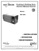
INSTALLATION SITE
HOOD INSTALLATION IS REQUIRED
In order to ensure proper ventilation, a minimum distance
of at least 6” (152mm) must be kept from the control panel
side [left] of the oven and any adjoining surfaces. In
addition to ventilation requirements, additional clearance
is needed for service access. A minimum distance of
18-inches (457mm) is strongly recommended.
Allow a minimum of 4” (102mm) from the right side of the
oven to allow the door to open to at least a 90° angle.
Fully opened, the door will extend up to a 225° angle. If
the oven is furnished with the retractable door option,
allow a minimum clearance of 6-1/2” (16cm).
Allow a minimum clearance of 4” (102mm) from the back
of the oven for plumbing connections.
Allow adequate clearance for the steam vent(s) located at
the top [right-rear] of the oven.
Do not install the oven adjacent to heat producing
equipment such as fryers, broilers, etc. Minimum
clearance recommended: 20” (50cm).
Place the Combitherm Oven on a stable, LEVEL horizontal
surface. For counter-top models, the oven stand must be
level. In addition, the overall height of the oven should
be positioned so the operating controls and shelves may be
conveniently reached from the front. Counter-top
installations must maintain 4" (102mm) minimum
clearance from surface by means of a Leg Extension
Assembly.
ALL INSTALLATION INSTRUCTIONS AND
REQUIREMENTS MUST BE STRICTLY OBSERVED.
IMPROPER CONNECTION OF THIS APPLIANCE
NULLIFIES ALL WARRANTIES.
COMBITHERM INSTALLATION AND MAINTENANCE MANUAL #6004/18
PG. 1
COMBITHERM® INSTALLATION and SPECIFICATIONS
TRANSPORTATION
➞
➞
THIS SIDE UP
COMBITHERM
6"
(152mm)
MINIMUM
4"
(102mm)
o
o
20"
(50cm)
MINIMUM
POWER
ON
OFF
COMBITHERM®
INSTALLATION SITE
ALLOW ADDITIONAL
ACCESS FOR SERVICE
18-inches (457mm) STRONGLY
recommended for service access

FOLLOWING ELECTRICAL CONNECTION,
THE FAN MUST ROTATE IN THE SAME
DIRECTION AS THE ARROW
LOCATED ON THE OVEN FAN
MOTOR.
THIS APPLIANCE WILL NOT FUNCTION
PROPERLY AND DAMAGE CAN OCCUR IF
THE MOTOR ROTATION IS NOT CORRECT.
COMBITHERM® INSTALLATION and SPECIFICATIONS
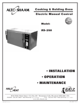
ELECTRICAL INSTALLATION
An electrical wiring diagram is located behind
the control panel on the left side of the oven.
The oven must be installed by a qualified
electrician. This appliance must be branch
circuit protected with proper ampacities, in
accordance with the wiring diagram located in
the electrical compartment of the oven. The
oven must be properly grounded in accordance
with the National Electrical Code and
applicable local codes.
CAUTION
ENSURE THE AVAILABLE
POWER SOURCE MATCHES
THE VOLTAGE STAMPED
ON THE NAMEPLATE OF
THE OVEN.
Wire size posted for the main incoming power
to the unit must match the minimum size listed
in the specifications applicable to the specific
oven model. For supply connections, locate the
wire size posted on the label located on the
electrical control box cover, behind the service
panel or elsewhere listed in this manual.
When connecting to a Delta-B (wild leg) on a 3-
phase system, the wild leg must be connect to
line 3.
Before operating the oven, check all cable
connections in the electrical connection area for
tightness since connections can loosen during
transport.
ELECTRICAL
CONNECTION
ELECTRICAL
PANEL
ELECTRICAL
PANEL
MOTOR
ELECTRICAL INSTALLATION
TERMINAL
BLOCK
TO CHANGE MOTOR DIRECTION, EXCHANGE
TWO OF THE INCOMING PHASES.
COMBITHERM INSTALLATION AND MAINTENANCE MANUAL #6004/18
PG. 2

COMBITHERM INSTALLATION AND MAINTENANCE MANUAL #6004/18
PG. 3
COMBITHERM® INSTALLATION and SPECIFICATIONS
WATER DRAINAGE
The oven must discharge through an indirect waste
pipe by means of an air gap. The drain thread is
1-1/4" NPT.
A union is required. Install a 1-1/4" (32mm)
diameter drain line. The drain line must always be a
positive gradient away from the Combitherm oven
and not more than 12" (305mm) before an air gap.
ATTENTION: In the U.S.A., this equipment is to be
installed to comply with the Basic Plumbing Code of
the Building Officials and Code Administrators
International, Inc. [BOCA], and the Food Service
Sanitation Manual of the Food & Drug
Administration [FDA]
If several units are to be connected to one drain pipe,
the dimensions of the pipe must be sufficient to allow
an unobstructed water drain system.
WATER SUPPLY
CONNECT TO POTABLE ( DRINKABLE) COLD WATER ONLY
WATER PRESSURE REQUIREMENTS: MINIMUM 45 PSI (3 BAR)
MAXIMUM 75 PSI (5 BAR)
Flush the water line at the installation site before connecting the oven to the water supply. A shut-off valve
and approved back-flow preventer must be installed when connecting the oven to the cold water intake. The
water supply line must be a minimum of 3/4-inch (19mm). A hose connector (
HO-22116) is supplied for
flexible hose connection to the cold water source. A water filtration system is recommended if the water
supply is between 7 and 9 grains of hardness. If water tests over 14 grains of hardness, the installation of a
water softener is stronly recommended.
PIPE SEALING TAPE (TEFLON®) MUST BE USED AT ALL CONNECTION POINTS.
The use of a pipe sealing compound is not recommended.
THE SHUT-OFF VALVE MUST BE IN THE OPEN POSITION WHEN THE OVEN IS BEING USED.
WATER DRAINAGE
DRAIN
LINE
SUPPLIED
WITH UNIT
1-1/4" (32mm) diameter NPT
Drain fittings
to be supplied
by others
WASTE PIPE
1-1/2" TO 2" minimum diameter
(c. 38mm to 51mm)
PROVIDE AIR GAP
After both water and electrical connections have been completed,
operate the oven in any cooking mode for a period of 15 minutes
and recheck the main power connections at the terminal block
to make certain they remain tight.

COMBITHERM INSTALLATION AND MAINTENANCE MANUAL #6004/18
PG. 4
COMBITHERM® INSTALLATION and SPECIFICATIONS
IMMEDIATELY FOLLOWING INSTALLATION:
BEFORE SWITCHING POWER SWITCH “ON”
✔ Make certain Power Switch is in the “OFF” position.
✔ Make certain all unnecessary articles are removed from the oven interior.
✔ Turn the water supply “ON” and make certain the connections do not leak.
✔ Flood the interior oven compartment floor with water from hand-held hose and check
to make certain the drain connections do not leak.
✔ Make certain the fan guard cover plate is in place and secure.
✔ Make certain the electrical connections are correct and sound.
IF ALL IS IN ORDER …
WITH DOOR CLOSED, TURN POWER SWITCH “ ON”
1. Press the STEAM program key to automatically fill the steam generator and heat the water to
stand-by mode temperature of 150°F (65°C).
●
The STEAM program LED light will illuminate.
●
The LOW-WATER LED light will illuminate and flash until the steam generator has been filled.
●
The STEAM LED light will illuminate and flash until the water temperature has reached the
stand-by mode temperature of 150°F (65°C).
●
When the STEAM LED light stops flashing, the oven is ready for immediate operation in the
STEAM mode or the selection of any other program mode.
2. Push SUPERHEATED STEAM AND CONVECTION program key. Press COOK TEMP
and use and to set the temperature to 250°F (120°C). Press and hold TIMER key for
continuous ON time until "–––" appears in the display .
Press START key to verify proper program operation.
●
The STEAM LED will illuminate periodically whenever the oven is producing steam.
●
The CONVECTION LED will illuminate periodically whenever the oven is producing convection heat.
●
The FAN LED will be illuminated throughout the entire cooking process.
Carefully open oven door, observing steam caution.
— Indicator lights for FAN and STEAM or CONVECTION should go “ OUT.”
Close the door and press STOP key to end program check.
3. Push CONVECTION program key. Press COOK TEMP and use and to set the
temperature to 250°F (120°C). Press and hold TIMER key for continuous ON time until
"–––" appears in the display .
Press START key to verify proper program operation.
●
The CONVECTION LED will illuminate periodically whenever the oven is producing heat.
●
The FAN LED will be illuminated throughout the entire cooking process.
Carefully open oven door, observing steam caution.
— Indicator lights for FAN and CONVECTION should go “ OUT.”
Close the door and press STOP key to end program check.
4. TURN POWER “OFF.”
THE OVEN IS NOW READY FOR NORMAL OPERATION.
For safe release of the cooking compartment steam,
initially open the door approximately 2" (50mm) only.
Stand behind the door as the hot steam is released.
CHECK
✔
✔
START-UP
✔
LIST
START
STOP
START
STOP
START
STOP
START
STOP
STEAM!

COMBITHERM INSTALLATION AND MAINTENANCE MANUAL #6004/18
PG. 5
COMBITHERM® INSTALLATION and SPECIFICATIONS
Model 7•14 10•18 20•20
Installation Data
Type of unit Counter-top Counter-top Floor Standing
Pan capacity 7 Full-size sheet pans* 10 Full-size sheet pans* 20 Full-size sheet pans*
(18" x 26" x 1") (18" x 26" x 1") (18" x 26" x 1")
*Additional wire shelves On wire shelves only On wire shelves only On wire shelves only
required for maximum capacity 14 Full-size pans 20 Full-size pans 40 Full-size pans
(20" x 12" x 2-1/2") (20" x 12" x 2-1/2") (20" x 12" x 2-1/2")
Side Rack spacing 2-5/8" (65mm) 2-5/8" (65mm) 2-5/8"
Net Weight 365 lb (166 kg) 514 lb (233 kg) 958 lb (435 kg)
Electrical specs
208/240V — 60 Hz, 1 ph At 208V At 240V Single Phase Not Available Single Phase Not Available
Power connection 13.9 kW 18.6 kW
Power convection 13.8 kW 18.3 kW
Power Steam 12.2 kW 17.5 kW
Motor Power 0.12 kW 0.3 kW
Current (Amps) 66.2 76.4
Terminal Block connection
2 Wire Plus Ground
AWG 3 or larger
208/240V — 60 Hz, 3 ph At 208V At 240V At 208V At 240V At 208V At 240V
Power connection 13.9 kW 18.6 kW 21.7 kW 28.9 kW 54.3 kW 72.4 kW
Current (Amps/phase) 38.2 44.1 60.3 69.6 150.9 174.4
Terminal Block connection
3 Wire Plus Ground 3 Wire Plus Ground 3 Wire Plus Ground
AWG 6 or larger AWG 2 or larger AWG 4 or larger
440/480V — 50/60 Hz, 3 ph At 440V At 480V At 440V At 480V At 440V At 480V
Power connection 15.3 kW 18.1 kW 30.3 kW 36.0 kW 60.8 kW 72.4 kW
Current (Amps/phase) 20.1 21.8 39.8 43.4 80.0 87.2
Terminal Block connection
3 Wire Plus Ground 3 Wire Plus Ground 3 Wire Plus Ground
AWG 6 or larger AWG 6 or larger AWG2 or larger
Noise Level 44 dB(A) 44 dB(A) 44 dB(A)
Construction Stainless Steel Type 304 Stainless Steel Type 304 Stainless Steel Type 304
Interior 20 gauge Interior 20 gauge Interior 20 gauge,
Exterior 20 gauge Exterior 20 gauge Exterior 20 gauge,
Hose length hand shower 86-5/8" (2200mm) 86-5/8" (2200mm) 86-5/8" (2200mm)
Cold water intake 3/4" NPT 3/4" NPT 3/4" NPT
Water pressure 45 to 75 psi 45 to 75 psi 45 to 75 psi
(3 to 5 bar) (3 to 5 bar) (3 to 5 bar)
Drain connection 1-1/4" NPT 1-1/4" NPT 1-1/4" NPT

COMBITHERM INSTALLATION AND MAINTENANCE MANUAL #6004/18
PG. 6
COMBITHERM® INSTALLATION and SPECIFICATIONS
Optional Recessed Door
Dimensions 7•14/10•18ec
L2 Width with door open 42-7/16" (1077mm)
M2 Depth with door open 67-7/16" (1712mm)
Y Unit width w/door open 73-9/16" (1868mm)
Z Protrudence forward 1-9/16" (40mm)
with door open
CLEARANCE
100mm
CLEARANCE
165mm
M
L2
J
D
H
AW1
F
B
KW1
E1
E2
K
E
G
A
OVEN CHAMBER
90° angle
Y
180° angle
Z
Dimensions 7•14 10•18ec 20•20ec
A Unit depth 40-3/16" (1020mm) 40-3/16" (1020mm) 45-7/16" (1153mm)
B Unit width 40-5/16" (1030mm) 40-5/16" (1030mm) 43-7/16" (1100mm)
C Unit height 32-1/2" (825mm) 44" (1118mm) 74-13/16" (1900mm)
D Electrical connection (E1) 4" (100mm) 4" (100mm) 4-5/16" 125mm)
E Electrical connection (E1) 13" (330mm) 13" (330mm) 9-13/16" (250mm)
F Drain (AW1) 24-7/16" (620mm) 24-7/16" (620mm) 31-1/2(800mm)
G Drain (AW1) 25/32" (20mm) 25/32" (20mm)
H Cold water con. (KW1) 2-3/8" (60mm) 2-3/8" (60mm) 3-15/16" (100mm)
I Cold water con. (KW1) 8-11/16" (220mm) 8-11/16" (220mm)
J Equipotential earth (E2) 6" (153mm) 6" (153mm)
K Equipotential earth (E2) 12-3/16" (310mm) 12-3/16" (310mm)
L Width with door open 43-5/8" (1108mm) 45-1/4" (1150mm) 47-11/16" (1211mm)
M Depth with door open 65-3/4" (1670mm) 66-3/8" (1685mm) 74-3/4" (1898mm)
N Foot position 9" (228mm) 9" (228mm)
O Foot position 25-19/32" (650mm) 25-19/32" (650mm)
P Foot position 3-11/16" (93mm) 3-11/16" (93mm)
Q Foot position 33-1/16" (840mm) 33-1/16" (840mm) 41" (1041mm)
R Diameter of footprint 1-9/16" (40mm) 1-9/16" (40mm)
S Oven chamber width 23-1/2" (596mm) 23-1/2" (596mm) 26-1/4" (667mm)
T Oven chamber depth 28-7/16" (722mm) 28-7/16" (722mm) 32-11/16" 830mm)
U Oven chamber height 20-5/16" (515mm) 31-13/16" (808mm) 60-1/4" (1530mm)
V Width hinge side 2-3/8" (60,5mm) 2-3/8" (60,5mm)
W Sill height 8-1/2" (216mm) 8-1/2" (216mm)
X Opening depth 1-13/16" (46mm) 1-13/16" (46mm)
Safety distance 4" (100mm) 4" (100mm) 4" (100mm)
(left, right, rear) minimum minimum minimum
Distance to another 20" (50cm) 20" (50cm) 20" (50cm)
heat source
Disappearing door free 6-5/16" (160mm) 6-5/16" (160mm)
space right-hand side
MINIMUM
CLEARANCE
100mm
100mm
M
L
J
D
H
AW1
F
B
KW1
E1
E2
K
E
G
P
A
T
X
OVEN CHAMBER
MINIMUM
CLEARANCE
A
O
N
I
KW1
COMBITHERM
Q
C
P
OVEN CHAMBER
S
V
W
U
R
X

COMBITHERM INSTALLATION AND MAINTENANCE MANUAL #6004/18
PG. 7
COMBITHERM® INSTALLATION and SPECIFICATIONS
Description 7•14 10•18 20•20
Chicken Roasting Rack
— 6 chicken capacity
(fits on full-size pan) SH-23000 SH-23000 SH-23000
— 8 chicken capacity
(fits on full-size pan) SH-23619 SH-23619 SH-23619
— 10 chicken capacity SH-22634 SH-22634 SH-22634
Grease Tray Package
(for use with roasting racks)
— 1-1/2" (57mm) deep 4758 4758 4758
— 2-3/4" (70mm) deep 14475 14475 14475
Leg Extension Assembly
(for counter-top placement) 15594 15594 N/A
Oven Cleaner CE-24750 CE-24750 CE-24750
Specially formulated for Combitherm Ovens
Twelve (12) containers/case, 1 quart. (c. 1 liter) each
Oven Stand
(wxdxh) 34-5/8" x 27-3/16" x 27-3/4"
(880mm x 690mm x 705mm)
— With Pan Shelf only 14342 14342 —
— With Pan Slides and Shelf 14343 14343 —
— Mobile With Pan Shelf only 14544 14544 —
— Mobile With Pan Slides and Shelf 14545 14545 —
Preheat Sealing Strip
—
For use in place of roll-in cart while preheating ——14568
Rack Management Trolley System
— Pan Rack Assembly 15639 15638 —
— Rack Track Assembly 14582 14582 —
— Base Trolley Assembly 15635 15635 —
Roll-In Cart
—
Interchangeable with 20•20W and QC-100 ——5815
Shelves, Stainless Steel Wire SH-22473 SH-22473 SH-22473
Stacking Hardware Kit
— 6•10 over 7•14 15813
— 7•14 over 7•14 15420
— 6•10 over 10•18 15835
Ventless Hood
(factory installation only) 15673 15681 —
Water Conditioner Kit
(includes 1 filter cartridge) FI-23014 FI-23014 FI-23014
Water Conditioner Cartridge
(1 filter cartridge) FI-23017 FI-23017 FI-23017
Safety and Operational
Precautions:
●
Before opening the oven door during normal operation, always press
the STOP key and wait a few seconds to allow the fan to stop rotating.
●
Before using the hand sprayer, wait until the cooking compartment
has cooled down to at least 130°F (54°C).
●
When using the hand sprayer, make certain the power switch is in the
OFF position.
●
Never use the oven cleaner or the hand sprayer to clean the outer
surface of the oven.
●
Flush the steam generator on a daily basis, clean the oven and oven
gasket on a daily basis.
●
To avoid unneccessary heat loss and the possibility of overheating the
convection heating elements,
NEVER preheat the model 20•20
without a roll-in cart (trolley) or a preheat sealing strip.
NEVER allow this model to remain in te stand-by mode for prolonged
periods
without a roll-in cart (trolley) or a preheat sealing strip.
Options and Accessories
Steam!!
For safe release of the cooking
compartment steam, initially open
the door approximately 2" (50mm)
only. Stand behind the door as
the hot steam is released.

COMBITHERM INSTALLATION AND MAINTENANCE MANUAL #6004/18
PG. 8
CONTROL PANEL OPERATING FUNCTION
bio
R
SUPERHEATED STEAM
AND CONVECTION
START
STOP
STEAM
CONVECTION
FAN
STEAM
CONVECTION
BIO-STEAM
RETHERM
Automatic
212° - 482°F
100° - 250°C
86° - 482°F
30° - 250°C
86° - 212°F
30° - 100°C
212° - 482°F
100° - 250°C
COOK TEMP CORE TEMP TIMER
34° - 210°F
1° - 99°C
DIST. BY ALTO-SHAAM® INC.
COMBITHERM
®
PROGRAM
1
2
3
4
56
7
89
0
ENTER
POWER
DRAIN
OPEN
COOL DOWN
OFF
FULL
SPEED
HALF
SPEED
2
5
6
7
8
9
10
11
12
14
15
22
20
17
INDICATOR LIGHTS
1. STEAM YELLOW:
Steam generator is activated. Indicator will
flash until steam generator is in the stand-by
mode with a water temperature of 150°F (65°C).
2. LOW WATER RED:
Flashes whenever the steam generator is in
the process of filling with a sufficient quantity
of cold water from water intake.
3. CONVECTION YELLOW:
Heating element for convection heat is activated.
4. FAN YELLOW:
Fan is activated.
PROGRAM FUNCTION
5. STEAM
●
Selection key and indicator light for
STEAM PROGRAM — 212°F (100°C).
●
Selection key for preheating the steam
generator.
●
Selection key for steam generator
“stand-by” function.
6. SUPERHEATED STEAM AND
CONVECTION
212° to 482°F (100° to 250°C)
Selection key and indicator light for
combination steam/convection — used
for roasting, braising, or baking. Steam
is automatically injected as required.
7. CONVECTION
86° to 482°F (30° to 250°C)
Selection key and indicator light for
convection heat only. Used for grilling,
roasting, or baking without steam.
8. BIO-STEAM
86° to 212°F (30° to 100°C)
Selection key and indicator light for
products which require a more gentle
steaming process.
9. RETHERM
212° to 482°F (100° to 250°C)
Selection key and indicator light for
rethermalizing (regenerating) plated meals.
10. DISPLAY
Three digit LED display indicates set
temperature, actual oven temperature,
cooking time, and program number
when oven is equipped with the
programmable menu.
11. COOK TEMP
Key to set oven cooking temperature
which can be indicated in degrees
Fahrenheit or degrees Celsius.
12. CORE TEMP
34° to 210°F (1° to 99°C)
Key used in any program mode to cook
by sensing the internal product probe
temperature.
13. TIMER — 1 to 199 minutes
Key used to set oven cooking time in
minutes.
14. DOWN ARROW
Key used to decrease the time or
temperature of a selected program
function.
15. UP ARROW
Key used to increase the time or
temperature of a selected program
function.
16. START/STOP
Key used to start or stop a selected
cooking program.
PROGRAMMABLE MENU
ON EQUIPPED MODELS
17. PRESET PROGRAM DISPLAY
Two digit LED display indicates number
of cooking steps when entering a
program menu and shows countdown
of the operational steps when operating
a program.
18. PRESET PROGRAM INDICATOR
Illuminates when entering or running a
program menu.
19. PRESET PROGRAM KEYS
Selection key for cook program number.
20. CLEANING KEY
Selection key for cleaning program.
21. ENTER KEY
Key to enter and recall cooking steps for
the programmable menu.
22. POWER SWITCH
Electric ON/OFF power switch includes
five positionsenabling the operator to
switch to any position while the oven is
operating in any program mode.
23. OFF
Power
OFF switch position.
24. FULL SPEED
Full fan speed position.
25. HALF SPEED
Reduced fan speed position
26. COOL DOWN
Switch position to allow fan to
remain operating with oven door
open to be used for rapid cool-
down of oven cavity temperature.
27. DRAIN OPEN
Power switch position to open
steam generator drain.
1
3
4
13
16
18
19
21
23
27
24
25
26

COMBITHERM INSTALLATION AND MAINTENANCE MANUAL #6004/18
PG. 9
COMBITHERM® ELECTRONIC CONTROL OPERATION
Fahrenheit or Celsius Selection
Turn Power Switch "OFF" and wait a minimum of two minutes.
After two minutes, press the Temp Key, the Timer Key, and the
Start/Stop Key at
the same time.
While pressing the three keys, turn the Power Switch to the Full Speed
position.
Release the three keys. The main display will indicate a service
program number such as
"S1."
Press the Up and Down Arrow Keys to change the service program
number to
"S2."
Press the Start/Stop Key when "S2" appears in the Main Display.
Press the Up and Down Arrow Keys to select 0 (CELSIUS) or 1
(FAHRENHEIT).
Press the Start/Stop Key to confirm the temperature scale selection.
The control is now set to operate in the temperature scale selected.
Note: Do not choose or change any service program other than "S2."
Changing any other factory setting could adversely affect oven performance.
Oven Start Up
Always begin daily operation of the combitherm with a clean oven.
Turn Power Switch "ON" to desired position — full fan speed or
half fan speed. Buzzer will sound.
Press Steam Program Key.
Water needed light flashes until steam generator is filled.
Steam LED light will flash until the water temperature has reached the
stand-by mode temperature of 150°F (65°C). When the light stops
flashing, the oven is ready to operate.
Cooking Programs
Standard cooking programs are steam, superheated steam and convection,
convection, Bio steam (optional) and retherm (optional).
Steam Program (212°F/100°C)
Press Steam Program Key and indicator light will appear.
Press Time Key. The main display will indicate last set time.
To reset the time from the previous operation, press the Up and Down
Arrow Keys to change the value shown in the display
(1 to 199 minutes).
Press the Start Key. The Fan LED will be illuminated throughout the
entire cooking process. The Steam indicator light will illuminate
periodically whenever the oven is producing steam. The Main display
will indicate time remaining. A buzzer will sound for one minute
signaling the end of the program.
Note: The buzzer can be turned off
immediately by pressing any program key.
START
STOP
DRAIN
OPEN
COOL DOWN
OFF
FULL
SPEED
HALF
SPEED
DRAIN
OPEN
COOL DOWN
OFF
FULL
SPEED
HALF
SPEED
DRAIN
OPEN
COOL DOWN
OFF
FULL
SPEED
HALF
SPEED
START
STOP
START
STOP
START
STOP

COMBITHERM INSTALLATION AND MAINTENANCE MANUAL #6004/18
PG. 10
COMBITHERM® ELECTRONIC CONTROL OPERATION
Cooking Programs (CONTINUED)
Superheated Steam and Convection Program
(212° to 482°F/100° to 250°C)
Press Superheated Steam and Convection Program Key. The indicator
light will illuminate.
Press Temperature Key. The main display will indicate the last set
cooking temperature.
To reset the cook temperature from the previous operation, press the
Up and Down Arrow Keys to change the value shown in the display.
Press the Time Key. The display will indicate the last set time.
To reset the time from the previous operation, press the Up and Down
Arrow Keys to change the value shown in the display
(1 to 199 minutes).
Press the Start Key. The Fan LED will be illuminated throughout the
entire cooking process. Steam indicator light will illuminate whenever
the oven is producing steam. The Convection indicator light will
illuminate whenever the oven is producing heat. Main display will
show time remaining. A buzzer signals the end of program.*
Convection Program (86° to 482°F/30° to 250°C)
Press Convection Program Key and indicator light will appear.
Press Temperature Key. The main display will indicate the last set
cooking temperature.
To reset the cook temperature from the previous operation, press the
Up and Down Arrow Keys to change the value shown in the display.
Press the Time Key. The display will indicate the last set time.
To reset the time from the previous operation, press the Up and Down
Arrow Keys to change the value shown in the display
(1 to 199 minutes).
Press the Start Key. Fan LED will be illuminated throughout the entire
cooking process. The Convection indicator light will illuminate
periodically whenever the oven is calling for heat. Main display will
indicate time remaining. A buzzer signals the end of program.*
Bio-Steam Program (86° to 212°F/30° to 100°C)
Press Bio-Steam Program Key and indicator light will appear.
Press Temperature Key. The main display will indicate the last set
cooking temperature.
To reset the cook temperature from the previous operation, press the
Up and Down Arrow Keys to change the value shown in the display.
Press the Time Key. The display will indicate the last set time.
Change the set time by pressing the Up and Down Arrow Keys.
Press the Start Key. Fan LED will be illuminated throughout the entire
cooking process. The Steam indicator light illuminates periodically
whenever the oven is producing steam. Main display will indicate
time remaining. A buzzer signals the end of program.*
START
STOP
bio
START
STOP
START
STOP
*Note: The buzzer signaling the end of the program can be turned off
immediately by pressing any program key.

COMBITHERM INSTALLATION AND MAINTENANCE MANUAL #6004/18
PG. 11
COMBITHERM® ELECTRONIC CONTROL OPERATION
Cooking Programs (CONTINUED)
Retherm Program (212° to 482°F/100° to 250°C)
Press Retherm Program Key and indicator light will appear.
Press Temperature Key. Last set cook temperature is displayed.
To reset the cook temperature from the previous operation, press the
Up and Down Arrow Keys to change the value shown in the display.
Press the Time Key. The display will indicate the last set time.
Change the set time by pressing the Up and Down Arrow Keys.
Press the Start Key. The Fan LED will be illuminated throughout the
entire cooking process. The Steam indicator light illuminates
periodically whenever the oven is producing steam. The Convection
indicator light illuminates whenever the oven is producing heat. The
Main display will indicate time remaining. A buzzer will sound for
one minute signaling the end of the program.
Cooking with Continuous Time
Select cooking program desired.
Press Temperature Key. Last set cook temperature is displayed.
To reset the cook temperature from the previous operation, press the
Up and Down Arrow Keys to change the value shown in the display.
Press and hold Timer Key for one (1) second until "---" is displayed.
Press the Start/Stop Key to begin cooking.
Press the Start/Stop Key to stop the cooking process when done.
To recall oven temperature while the oven is operating:
Recall Set Temperature: Press Temperature Key.
The main display will indicate the set cook temperature for
three (3) seconds.
Recall Actual Temperature: Press and hold the Temperature Key
for five (5) seconds. Display will then indicate the actual temperature
while you continue to press the temperature key.
To change set cook temperature while the oven is operating:
The Main display will indicate time remaining.
Press Temperature Key. The main display will indicate the set cook
temperature.
To reset the cook temperature, press the Up and Down Arrow Keys to
change the value shown in the display.
To recall set time while the oven is operating:
The Main display will indicate time remaining.
Press Time Key. The main display will indicate the set time for three
(3) seconds.
To change set time while the oven is operating:
The Main display will show time remaining.
Change the remaining time by pressing the Up/Down Arrows.
bio
START
STOP
START
STOP
R
R
START
STOP

COMBITHERM INSTALLATION AND MAINTENANCE MANUAL #6004/18
PG. 12
COMBITHERM® ELECTRONIC CONTROL OPERATION
Cooking Programs (CONTINUED)
Core Temperature Program (34° to 210°F/ 1° to 99°C)
As an alternative to timer operation, this option can be used in any
program mode to cook by sensing internal product temperature. In any
program mode other than steam, it is necessary to preheat the oven for a
minimum of 5 minutes before loading product.
Select cooking program desired.
Press the Core Temperature Key. The display will indicate the last set
internal product temperature. If necessary, change the set core
temperature by pressing the Up/Down Arrows to change the value
shown in the display.
Do not set the timer when using the core temp program for the
cooking function!
Load product and insert product probe. The probe must be inserted
into the center of the product to assure an accurate temperature
reading. Only the tip of the probe measures internal product
temperature.
Press Start Key. The display will briefly indicate the selected probe
cut-off temperature, immediately followed by the actual internal
product temperature. The Fan LED will be illuminated throughout
the entire cooking process. The Convection indicator light will
illuminate periodically whenever the oven is calling for heat. When
the set core temperature has been reached, a buzzer will sound for
one minute signaling the end of the program.
Note: The buzzer can
be turned off immediately by pressing any program key.
To recall set core temperature while the oven is operating:
The Main display will display actual internal product temperature.
Press and hold the Core Temperature Key. The main display will
indicate the set core temperature. When released, the display will
return to the actual internal product temperature.
Note: After using the core temperature mode, pressing the
timer key will allow you to use any other mode.
Cool Down Function
At times it may be necessary to quickly cool the oven cavity for a
temperature sensitive product.
Turn the power switch to "Cool Down."
Observing the steam caution, open the oven door approximately
5" (127mm) to let the hot air escape from the interior.
After approximately two minutes, turn the power switch to full or
half speed, which will turn the fan off.
START
STOP
bio
R
DRAIN
OPEN
COOL DOWN
OFF
FULL
SPEED
HALF
SPEED

COMBITHERM INSTALLATION AND MAINTENANCE MANUAL #6004/18
PG. 13
COMBITHERM® ELECTRONIC CONTROL OPERATION
Programmable Menu (DELUXE MODEL OPTION)
Programming
Begin programming with the oven with the power switch in the
"
OFF" position.
Turn oven power switch "ON" to the full fan speed position. Two
flashing points will appear in the Main display and a buzzer will
sound.
Simultaneously press and hold both the Up and Down Arrows for
a period of 5 seconds. P01 or the last program menu number
used will appear in the Main display. Program indicator light will
illuminate. You are now in the programming mode.
Assign a number between 1 and 99 to the product to be
programmed and enter that number on the Program Keypad.
The number entered will appear in the Main display preceded by
the letter
"P." The Program display will indicate "0".
Press the Program Enter Key.
Press "1" to enter the first program cooking step. The Preset
Program display will indicate
"1".
Select the cooking program desired (Steam, Superheated Steam
and Convection, Convection, Bio-Steam or Retherm).
Press Temperature Key. Main Display will indicate the last set
cooking temperature or the fixed Steam Program temperature.
Adjust the cook temperature by pressing the Up/Down Arrows.
To cook by time — press the Timer Key. Main Display will
indicate the last set cooking time. Change the set time by pressing
the Up or Down Arrow Keys.
To cook by internal product temperature — press the Core
Temperature Key. Main Display will indicate the last set internal
product temperature. If necessary, adjust the set internal product
temperature by pressing the Up/Down Arrows.
Press
"2" for the 2nd cooking step to continue entering additional cooking
steps in the program. Select the cooking program desired, temperature,
time or core temperature as instructed above. Continue this format to
add up to a total of five cooking steps.
When the last cooking step has been entered, press and hold the
"
ENTER" key. Release the Enter Key when the beep sounds.
You may now enter another numbered preset program by selecting that
Numbered Preset Program Key and repeat the instructions above. You
may enter up to 99 individual product cooking programs.
When programming has been completed, press and hold the Start Key
for two (2) seconds. Menu Program Indicator Light will no longer be
illuminated. Two (2) flashing points will again appear in the Main
display. You have now exited the program mode.
Note: After programming a specific product into memory in the
Programmable Menu, it is very important to make a permanent record of
the product and the program number assigned.
1
ENTER
1
START
STOP
Cook by
time
— or —
Cook by
core
temp.
ENTER
DRAIN
OPEN
COOL DOWN
OFF
FULL
SPEED
HALF
SPEED
bio
R

COMBITHERM INSTALLATION AND MAINTENANCE MANUAL #6004/18
PG. 14
COMBITHERM® ELECTRONIC CONTROL OPERATION
Programmable Menu (CONTINUED)
Previewing a Preset Cooking Program
Enter the assigned program number on the Program Keypad that you
wish to review. The Main display will indicate the selected program
number preceded by the letter
"P." The Program Display will indicate
the total number of cooking steps programmed.
Press the Enter Key.
Press "1" to review the first cooking step. The programmed cooking
mode light will illuminate.
The Main Display will indicate the programmed cooking temperature.
When programmed to cook by time — press the Timer Key. The Main
Display will indicate the total time originally programmed.
When programmed to cook by internal product temperature — press
the Core Temperature Key. The Main Display will indicate the internal
product temperature originally programmed.
Press
"2" on the Program Keypad to review the second cooking
step, and continue as indicated above until each cooking step has
been reviewed.
When the last cooking step has been recalled, press the "ENTER" key to
exit the recall mode.
Deleting a Preset Cooking Program
While in the Program mode, enter the program number to be deleted
on the Program Keypad. The Main Display will indicate the selected
program number preceded by the letter
"P." The Program Display will
indicate the total number of cooking steps programmed.
Press the Enter Key.
Press and hold the Start Key for one second, releasing the key when
the buzzer sounds. The program has been erased from the
programmable control memory. Continue programming or exit the
program mode by pressing and holding the Start Key for a period of 2
seconds. The Menu Program Indicator Light will go out, while two
flashing points appear in the Main Display.
Change a Preset Cooking Program
While in the Program mode, enter the assigned program number to be
changed on the Program Keypad. The Main Display will indicate the
selected program number preceded by the letter
"P." The Program
Display will indicate the total number of programmed cooking steps.
Press "1" on the Program Keypad to make a change in the first cooking
step. The Programmed cooking mode light will illuminate.
The Main Display will indicate the programmed cooking temperature.
To adjust any of the programmed settings, press the Up/Down
Arrows after pressing the corresponding key for the setting which
requires a change.
Press "2" on the Program Keypad to review and change the second
cooking step and continue as indicated above until each cooking step
has been reviewed and changes made.
Following entry of the last cooking step change, press and hold the
Enter Key. Release the Enter Key when the buzzer sounds.
When programming changes have been completed, press and hold the
Start Key for a period of 2 seconds. Menu Program Indicator Light
will go out, while two flashing points appear in the Main Display.
ENTER
1
2
3
4
56
7
89
0
ENTER
1
2
3
4
56
7
89
0
ENTER
1
2
3
4
56
7
89
0
ENTER
ENTER
1
1
START
STOP
ENTER
START
STOP
ENTER
bio
R
Cook by
time
— or —
Cook by
core
temp.

COMBITHERM INSTALLATION AND MAINTENANCE MANUAL #6004/18
PG. 15
COMBITHERM® ELECTRONIC CONTROL OPERATION
Programmable Menu (DELUXE MODEL OPTION)
Cooking
Note: After programming a specific product into memory in the
Programmable Menu, it is very important to make a permanent record of
the product and the program number assigned.
Turn oven Power Switch "ON" to the appropriate fan speed
position.
Note: Preheat the oven for a minimum of 5 minutes
before loading product.
Press and set cooking Time to preheat or assign a permanent
number and program the preheating function into Programmable
Menu memory.
Enter the assigned program number on the Program Keypad.
The Main Display will indicate the selected program number
preceded by the letter
"P." The Program Display will indicate the
total number of cooking steps programmed and will count-down
from this number.
Press the Start Key.
When cooking by time — the Main Display will indicate the time
remaining in the active cooking step.
When cooking by internal product temperature — insert probe in
product. The Main Display will indicate the current internal
temperature of the product.
When the full preset cooking program has completed, the oven will
automatically cycle
OFF and the buzzer will sound for a period of one
minute. The buzzer can be turned off immediately by pressing any
program key.
Cleaning Program
Spray oven cleaner in a cooled oven as described under "Cleaning
and Maintenance". Close oven door securely.
Turn oven Power Switch to the Full Fan Speed position.
Press the Clean Key. Main display will show "CLN". Preset
Program display will indicate "1".
Press the Start Key. "CLN" will flash for 10 minutes during which
time the fan will not operate. "CLN" will then illuminate
continuously for another 10 minutes while the oven is cleaning
itself. The fan operates during this time. A buzzer will sound
for one minute signaling the end of the program and the oven
will automatically shut down.
Open door and rinse the interior of the oven according to the
directions listed under "Cleaning and Maintenance."
START
STOP
DRAIN
OPEN
COOL DOWN
OFF
FULL
SPEED
HALF
SPEED
1
2
3
4
56
7
89
0
ENTER
START
STOP

COMBITHERM® CLEANING and MAINTENANCE
COMBITHERM INSTALLATION AND MAINTENANCE MANUAL #6004/18
PG. 16
Establishing a routine cleaning and maintenance schedule will help keep the oven running at top
operating efficiency and is an absolutely essential part of a comprehensive sanitation program.
Good equipment maintained and kept clean works better and lasts longer. PROTECT
YOUR INVESTMENT.
Daily Oven Cleaning
To be performed at the end of each production day or between production shifts.
Daily Steam Generator Flush
When operating the oven on a regular basis, the steam generator must be flushed once a day. This
procedure will prevent lime deposits and scale build-up from forming in the steam generator.
Weekly Steam Generator Back-Flush
Back-flushing the oven on a weekly basis prevents lime deposits and scale build-up from forming in the
entire steam generating system. It will flush the areas missed with the daily steam generator flushing
procedure. This procedure should be followed once a week, in place of the daily steam generator flush.
Monthly Decalcification
It is VERY important to decalcify the oven , particularly in areas with extremely hard water. This
procedure should be followed once a month, in place of the daily steam generator flush.
Daily Gasket Cleaning
It is important to prolong the life of the oven gasket by cleaning this item on a daily
basis. Routine cleaning will help protect the composition of the gasket from
deterioration caused by acidic foods. Remove pull-out gasket and wash in hot soapy
water or in the dishwasher. Always replace the gasket before cleaning the oven
interior or operating the oven.
Probe Usage and Cleaning
After each use of the CORE TEMP program mode, wipe the probe tip with a clean paper towel to remove food debris.
Follow by wiping the probe with a disposable alcohol pad. Return the probe to the proper door bracket position.
Probe Cleaning Procedures
1.
Remove all food soil from probe between loads and at the end of each production shift. Wipe
entire probe, cable assembly, and probe holding door bracket with warm detergent solution
and a clean cloth.
2. Remove detergent by wiping the probe, cable, and bracket with clean rinse water and a
cloth.
3. Wipe probe and probe bracket with disposable alcohol pad or sanitizing solution
recommended for food contact surfaces.
4. Allow probe and cable to air dry in probe holding door bracket.
5. Rewipe the probe with a disposable alcohol pad prior to inserting in a new food product.
Roll-In Cart/Food Trolley Cleaning
1. Remove food trolley to a cart wash area. Trolleys may be cleaned using any mild cleaning detergent and
warm water.
2. Hand wipe all framing, slides, drip pan, and base. Thoroughly clean debris from the casters. A spray
hose can be used for easier cart cleaning.
3. Remove detergent solution with warm water.
4. Wipe or spray with a sanitizing solution designed for use on metal and vinyl food contact surfaces.
5. Allow trolley to air dry.

CLEANING and MAINTENANCE
COMBITHERM INSTALLATION AND MAINTENANCE MANUAL #6004/18
PG. 17
2. Wearing safety glasses and rubber gloves,
generously spray the interior oven surfaces with
an even coating of Combitherm Liquid Oven
Cleaner. Spray all built-in components, shelves,
side racks, and pans. Unfasten the Side Rack
Shelf-Support on side-rack equipped models
and lean it against the opposite wall of the oven.
On equipped models, loosen thumb screw and
swing Fan Guard Cover Plate
outward or
unfasten removable Fan Guard Cover Plate
and lean against the opposite wall of the oven.
Spray the back of the Fan Guard Cover Plate, the
oven fan, and the left-hand side of the oven.
3. Insert the Combitherm Liquid Oven Cleaner
spray nozzle directly into the Steam By-Pass Port
and spray several times.
4. Securely close the oven door.
OVENS WITHOUT PROGRAMMABLE CONTROL:
Let the solution stand for a minimum of 10 minutes.
Turn the Power Switch to the ON position or to the
Full Speed fan position on fan equipped models.
Press the Steam program key.
Set the timer for ten minutes.
Continue with instruction number 5.
OVENS WITH PROGRAMMABLE CONTROL:
Turn Power Switch to the Full Speed fan position.
Press the Cleaning program key.
●
The Main Display will indicate "CLN."
●
The Program Display will indicate "1."
Press Start key.
●
"CLN" will flash in the Main Display for 10
minutes with no fan operation.
●
After 10 minutes "CLN" will light steadily and
the fan will begin operation of the cleaning cycle.
A buzzer will sound for one minute signaling the
end of the cleaning program and the oven will
automatically shut down.
Continue with instruction number 6.
5. When the buzzer signals the end of the
cleaning process, press the Steam
program key to deactivate the audible signal.
Turn the Power Switch to the OFF position.
6. Open the oven door. Use the hand held hose and
direct a stream of water into the Steam By-Pass
Port to rinse away oven cleaner residue.
7. Rinse the interior and all sprayed components
with the hand-held hose. Make certain to
thoroughly rinse all surfaces to remove any
cleaning solution residue. Use a non-abrasive
cleaning pad for any problem areas.
8. Close the swing out Cover Plate or replace the
removable Fan Guard Cover Plate
by lifting up
into the proper channel. Lock the cover into
place and tighten thumb screws.
RUBBER GLOVES AND PROTECTIVE EYE
WEAR MUST BE WORN WHEN USING
THE OVEN CLEANER.
USE AUTHORIZED
COMBITHERM LIQUID
OVEN CLEANER ONLY.
LEAVE DOOR SLIGHTLY OPEN AFTER CLEANING
1. IF THE OVEN IS HOT:
Turn the Power Switch to the OFF position
and allow the oven to cool to approximately
130°F (54°C). Leave the oven door open
during the cooling process.
Oven Cleaning Clean the oven daily at the end of the production day or between production shifts.
➤
IF THE OVEN IS COLD:
Turn the Power Switch to the ON or Full Speed fan
position and preheat the oven at 130°F (54°C) for 10
minutes in Superheated Steam and Convection. After
preheating, turn the Power Switch to the OFF position.
➤
O
O
v
v
e
e
n
n
C
C
l
l
e
e
a
a
n
n
e
e
r
r
COMBITHERM
STEAM EXIT
PORT
OVEN LIGHT
STEAM
GENERATOR
DRAIN CAP
OVEN DRAIN
SIDE RACK
SHELF
SUPPORT
FAN
STEAM BY-
PASS PORT
DECALCIFICATION PORT
bio
R
SUPERHEATED STEAM
AND CONVECTION
START
STOP
STEAM
CONVECTION
FAN
STEAM
CONVECTION
BIO-STEAM
RETHERM
MFG. BY ALTO-SHAAM® INC.
COMBITHERM®
POWER
1
2
3
4
56
7
89
0
ENTER
OFF
FULL
SPEED
HALF
SPEED
COOL DOWN
DRAIN
OPEN
FAN GUARD
COVER
PLATE

COMBITHERM® CLEANING and MAINTENANCE
COMBITHERM INSTALLATION AND MAINTENANCE MANUAL #6004/18
PG. 18
Steam Generator Flush
PERFORM DAILY
WITH THE OVEN AT ROOM TEMPERATURE
1. Turn the oven Power Switch to the "Drain Open"
position. A buzzer will sound and water will
begin to drain from the generator directly into the
oven drain flushing accumulated deposits from
the generator through the system.
2. Allow the water to continue to flow for a period
of 30 seconds.
3. Remove the hand-held hose from the side of the
oven and direct a stream of fresh water directly
into the Steam Exit Port .
4. Leave the Power Switch in the "Drain Open"
position and press the Steam key. A new
supply of fresh, cold water will begin to flow
through the steam generator.
5. After a period of two minutes have lapsed, turn
the Power Switch to the OFF position.
Decalcification
PERFORM ONCE A MONTH
in place of the daily steam generator flush.
WITH THE OVEN AT ROOM TEMPERATURE
1. Turn the power switch to the "Drain Open"
position. A buzzer will sound and water will begin
to drain from the generator directly into the oven
drain, flushing accumulated deposits from the
generator through the system. Allow the water to
continue to flow for a period of 30 seconds.
2. Turn the Power Switch to the "OFF" position.
3. Using hand protection, open
Decalcification Port . Use a funnel to
pour one-half gallon (c. 2 liters) of
distilled white vinegar into
Decalcification Port .
4. Firmly screw the cover back on the
Decalcification Port
before
proceeding to avoid extremely hot
water from exiting the opening.
5. Turn the Power Switch to the Full Speed fan
position and press the Steam program key. When
the Steam LED light stops flashing, the oven is in
stand-by mode. Allow the oven to remain in the
stand-by mode for a minimum of 10 minutes.
DO NOT OPERATE ANY PROGRAM
FUNCTION WITH VINEGAR IN THE
STEAM GENERATOR SYSTEM.
6.
Following the 10 minute stand-by period, the oven
must be flushed to remove remaining deposits and
vinegar solution from the steam generator.
7. Turn the oven Power Switch to the "Drain Open"
position. A buzzer will sound and water will
begin to drain from the generator directly into the
oven drain to flush accumulated deposits and
vinegar from the system.
8. Allow the water to continue to flow for a period
of 30 seconds.
9. Remove the hand-held hose from the side of the
oven and direct a stream of fresh water directly
into the Steam Exit Port .
10. Leave the Power Switch in the "Drain Open"
position and press the Steam key. A new
supply of fresh, cold water will begin to flow
through the steam generator.
11. After a period of two minutes have lapsed,
turn the Power Switch to the OFF position.
OVEN MUST BE AT ROOM TEMPERATURE
STEAM EXIT
PORT
OVEN LIGHT
STEAM
GENERATOR
DRAIN CAP
OVEN DRAIN
SIDE RACK
SHELF
SUPPORT
FAN
STEAM BY-
PASS PORT
DECALCIFICATION PORT
bio
R
SUPERHEATED STEAM
AND CONVECTION
START
STOP
STEAM
CONVECTION
FAN
STEAM
CONVECTION
BIO-STEAM
RETHERM
MFG. BY ALTO-SHAAM® INC.
COMBITHERM®
POWER
1
2
3
4
56
7
89
0
ENTER
OFF
FULL
SPEED
HALF
SPEED
COOL DOWN
DRAIN
OPEN
FAN GUARD
COVER
PLATE
DURING DECALCIFICATION THE WATER FLOWING
FROM THE DRAIN CAP IS EXTREMELY HOT!
●
USE HAND PROTECTION WHENEVER TOUCHING
THE STEAM GENERATOR DRAIN CAP.
●
DO NOT TOUCH THE WATER
FLOWING OUT OF THE STEAM
GENERATOR DRAIN CAP OR
STEAM GENERATOR DRAIN.
Page is loading ...
Page is loading ...
Page is loading ...
Page is loading ...
Page is loading ...
Page is loading ...
Page is loading ...
Page is loading ...
Page is loading ...
Page is loading ...
Page is loading ...
Page is loading ...
Page is loading ...
Page is loading ...
Page is loading ...
Page is loading ...
Page is loading ...
Page is loading ...
Page is loading ...
Page is loading ...
Page is loading ...
Page is loading ...
Page is loading ...
Page is loading ...
Page is loading ...
Page is loading ...
Page is loading ...
Page is loading ...
Page is loading ...
/