Page is loading ...

DX7
Staggered Electronic
Crossover Network
OWNER’S MANUAL
TECHNOLOGIES

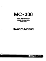
DX7 WIRING DIAGRAM
Connect lo Remote Turn-on
-
of Aftermarket Source
Umt,
or
leave Jumper connected to 12V
11
High level Input
IS
not used
Some OEM radios may or may not require
connection of the radio’s speaker ground.
Fuse
Check your radio’s owner’s manual.
r
I
Battery
Ill
n
r
Delayed
Remote
Turn-on
Power
Ampllfler
DX7
Staggered
Ebcironic
Crossover Network
OWNER’S
MANUAL
OVERVIEW
Congratulations on your purchase of the Soundstreom DX7 electronic
crossover. You now own one of the finest and most versatile electronic
crossovers made, a
precision
component which provides true audiophile
performance.
Please make note of the following information for your records. Doing
so will protect your investment should your DX7 ever require service or
replacement.
Model
Number: Soundstreom DX7 Electronic Crossover
Serial
Number:
Dealer’s Name
&
City:
Date of Purchase:
Dote of Installation:
This Soundstreom product is the result of American design and crafts-
manship, and was manufactured using the highest quality control stan-
dards. Your DX7 should
deliver
many years of pleasure.
We recommend that you review this manual in order to familiarize your-
self with the remarkable capabilities of the DX7. Doing so will ensure
your obtaining the best possible performance from the product.
Please
retain this manual for future reference.
&Channel
input/7-Channel
Output Design
The Soundstream DX7 electronic crossover is a four-channel
in/seven-
channel out design which retains the full fading capability of your
source(s).
it
provides a pair of subwoofer
outputs
and a summed center
channel output in addition to he usual front (L&R) and rear (L&R) out-
puts. (See diagram.)
Htgh Level Input
GVXKld
Left
Rear
1
Riiht
Rear
Lelt Front
Right Front
Rear
lnKhll
Len
In
Right
In
1
H,gh
Left Out
High Right Out
IiiweriRamotes
112”
Control
I”
Ground
1
Remote Out
Remote In
pmni
In/Out
1
subwoofer
OUI
’
Lelt Sub Out
Uiiht
Sub Out
Len
In
Right In
I
High
Left Out
Hagh
Center Out
Hagh
Right Out
1

CROSSOVER
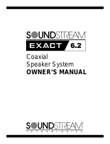
Symmetrical Configuration
CONFlGUfU4TlONS
,
.\
/*
’
\
\
.
I
I
-
/
,
106l-k
‘\
I
,
I
I’
\
/
\
20Hz
200Hz
PkHz
POkHz
The standard way to divide up the frequencies your system reproduces is
to have one speaker pick up exactly where the previous one has left off.
A single crossover frequency is chosen and the response is shaped such
that the subwoofers and the mid-bass drivers are each reproducing half
of the music at
the
crossover point, for a smooth transition from one
ta
the next. This is the common configuration for most crossovers, despite
the fact that it is
ohen
inappropriate for the automotive environment.
Asymmetrical Staggered Configuration
I
75Hz
15Oliz
I
I
1’;
I
’
I’
\
\
20Hz 200Hz
2kHz
20kHz
Great improvements in system definition and
clariIy
are made possible
by making the high-pass and low-pass sections of the crossover inde-
pendent of one another. This is because most cars have a mid-bass “res-
onance” somewhere between 75 and 180 Hz, meaning that those
frequencies are unnaturally emphasized by the car itself. This gives a
muddy,
boomy
sound to an otherwise excellent system. But this resonant
peak in the car’s response can be eliminated by deliberately leaving a
gap between the subwoofer’s range and the mnge in which the rest of
the speakers operate. This creates a precise “dip” in the response of the
system which compensates for the car’s “peak,” restoring accurate,
uncolored sound.
DESIGN
Automatic Priority Switching
FEATURES
The
DX7 can accept both high level
(speaker
level) and low level (line
level) inputs, and will automatically switch from one to the other without
user intervention. This capability allows the use of the existing
factory-
installed radio with an aftermarket source (a CD changer, for example).
The DX7 will mute the input from the factory radio when it senses an
2
input from the CD changer, and will revert
to
the mdio automatically a
few seconds after the CD changer has been turned off.
Remote Control Source Switching
If your CD changer (or other aftermarket
saurce)
has a remote turn-on
control output, it can be connected ta the “Control In” input on the DX7
for switching between sources. In this mode, the DX7 will switch to the
Low Level input when it senses that the CD changer has been turned on,
and, in a few
seconds,
will revert
to
the factory-installed unit (at the High
Level input) when the CD changer or other aftermarket source is turned
off. After you have turned off the Low Level input (CD changer or other
aftermarket source) the DX7 will take a few seconds to automatically
revert to the High Level input when the Low Level input has been
switched off.
Input and Output
level
Controls
A full complement of input and output level controls is provided to allow
proper matching and tuning of the system. Input level controls for both
High Level and Low Level inputs can be used to match the relative vol-
umes of the two sources, avoiding the abrupt (and potentially danger-
ous) changes in volume which sometimes occur when switching between
sources in less sophisticated systems. Output level controls for all chan-
nels compensate for differences in amplifier and speaker sensitivity, so
that appropriate Front-Rear and Left-Right balance can be obtained with
both the Fader and the Balance controls of the
xxlrces
set to their neutral
position. This guarantees the maximum range of these controls during
everyday use.
Summed Center Channel Output
A summed center channel output is provided on the DX7 which elimi-
nates the “hole-in-the-middle” effect common
to
many car stereo instal-
lations. This undesirable effect is the result of our close proximity to the
front speakers and the constraints on their placement in an automotive
environment. By placing a center-channel speaker in the middle of the
dash and using this output to drive its amplifier, a more satisfying, con-
vincing front image is created. The effect works equally well for both
front-seat passengers, often eliminating the everyday use of the balance
control.
The DX7 also incorporates an independent high-pass filter which is con-
tinuously variable from
300-1000
Hz, with a 6
da/octave
slope. This
extra measure of control gives the installer the ability to determine the
effect of the center channel speaker, ranging from merely adding some
additional “air” and sparkle to the sound, to providing a full center
image for female
vocalisk.
Amplifier Turn-On Delay
The remote turn-on lead (sometimes called an “amplifier lead”) from your
source unit should
be
attached to the Remote Input on the DX7 and can
be used in either of two ways. If
the
signal from the remote lead is con-
nected to both the DX7 and the amplifier(s) in parallel, all units will
3

be powered up simultaneously. If the amplifier(s) receive their turn-on
signal from the Remote Output of the DX7, a four or five second delay
will be introduced between the time the DX7 powers up and when the
amplifiers are switched on. This delay allows both
the
source unit and the
DX7 a chance ta “settle” after turning on before the amplifier becomes
active, which prevenk low
le/$
turn-on
transienk
being amplified.
High-Pass Frequency Selection By SIP Modules
The high-pass frequency selection in the Soundstream DX7 is
imple-
P
mented
through the use of Single In-Line Package modules. The use of
SIPS
provides far more accurate inter-channel frequency matching, for
b
superior imaging and perceived channel balance. A wide variety of
SIPS
are available, combining the finest accuracy with almost unlimited flexi-
bility. (See the
tabI
e
on he rear cover for a
list
of available frequencies.)
Separate
SIP
modules are used for the front and rear portions of the
crossover, to allow the most appropriate selection of high-pass fre-
quency, regardless of the speakers used. For example, if space con-
straints in your car require you to use a small speaker in the front which
has limited mid-bass capability, you can increase the system’s overall
dynamic range by raising the high-pass frequency for those front speak-
ers alone. You can then rely more heavily on the (presumably larger)
speakers you have in the rear for your mid-bass, while the subwoofers
handle the deep bass.
Switchable Low-Pass Crossover Slope
The
subwaofer
outpuk
may be run in either of two modes: 12
dB/octave
in stereo, or 24dB/octave in mono. This unusual feature bears some
explanation. If your system design requires your
subwoofers
to operate
at relatively high frequencies (say, above 150 Hz), you may choose ta
retain the full stereo effect in those drivers. This has some advantage,
since it is generally conceded that we can localize sounds beginning
somewhere between 150
-
200 Hz and upward.
On the other hand, if your subwoofers will be limited to frequencies
below 150 Hz, it is better to opt for the steeper slope, monophonic sig-
nal. This accomplishes several objectives: dynamic range is enhanced by
more sharply limiting drivers to their optimal ranges; more amplifier
power is reserved for the deepest bass, for greater impact; and any pos-
sible low-bass cancellation between the subwoofers is eliminated, since
)
they are reproducing precisely the same signal. (This assumes they have
been properly installed with regard to polarity, of course.)
)
Continuously Variable Low-Pass Frequency Adjustment
The turnover frequency of the low-pass portion of the crossover is contin-
uously variable from approximately 35 Hz to 200 Hz in the mono mode
(40-240 Hz in the stereo mode). This allows extremely precise
fine-
tuning of the width and depth of the “dip” created by staggering the
crossover poink, for the flattest, most accurate response in the car. (See
;
Asymrnehical
Sggered
Configumlif8n, on page 2.)
Front Bass
Foldback
Some cars have such a significant resonant peak that a rather large dip
is required to restore flat response. In these situations, instruments which
have deep bass sometimes appear
to
move backward in the car, toward
the subwoofers. The DX7 has an innovative Front Bass
Foldback
feature
which eliminates this problem by re-introducing some of the deep bass
material (below the staggered crossover’s “dip”) to the front speakers. In
this way, the deep bass is still perceived as coming from the front speak-
ers, even though the subwoofers continue to do most of the work at
those frequencies. Effective power handling and dynamic range in the
front speakers remains high due to the use of an additional high-pass
filter which limik the deepest portion of the “subwoofer” bass they are
expected
to
reproduce. The overall level of this “folded-back” bass mate-
rial relative to overall system volume is adjustable at the crossover,
ta
avoid overloading the bass capabilities of small front speakers.
Switchable Subwoofer
Tmcking
The subwoofer output can be quickly and easily switched to track with
either the front speakers or the rear speakers, or with both pairs of
speakers. In this last case, the relative volume of the subwoofers will be
independent of the
fader
control setting, and will appear to track with
the system volume control only.
Subsonic Filter
The DX7 also incorporates a permanent 24
de/octave
subsonic filter to
eliminate dangerous (though inaudible] signals below
20
Hz from enter-
ing the amplifiers. This ensures that the power of your amplifiers and the
excursion capability of your subwoofers are being used for music that
you can hear- rather than for noise which can only damage your valu-
able
componenk.
INSTALLATION
Proper
install
a
h
on
and adjustment of your DX7 will reward you with reli-
able operation and optimum performance. Automotive sound system
installations can be tricky, especially for first-timers. For this reason, you
may want to consider using a professional installer who has the tools
and (more importantly) the experience to do the
Iob
right.
At the beginning of this manual is a diagram of recommended, proven
system variations employing the DX7. Review these systems before
attempting your own installation. You may find some ideas which you
will wish to incorporate into your system design.
Location and Mounting
The DX7 is compact and generates virtually no heat. It can be located
almost anywhere within the passenger compartment or in the trunk. Da
not install the DX7 in the engine compartment or in any outside location
exposed to dirt and moisture. The DX7 should be mounted firmly to your
car’s chassis (or an “amp rack”) using the provided screws. Use the DX7
itself as a template for making pencil marks where you intend to drill,
4
5

but under no circumstances drill through the holes in the
DX7’s
flanges,
as you may inadvertently damage the crossover.
It is a good idea
to
“bench test” the system prior to mounting any com-
ponents. If you have a
+12V
power source, you can connect and test the
components outside the car. Or, you can connect them inside the car
before mounting them. Either way, connect the components exactly as
you intend to in the final installation; make all power connections last,
test the system, then disconnect all power until the final installation is
complete.
Wiring
Predetermine how you car’s wiring is laid out. Keep all wiring inside the
vehicle. Good audio practice suggests keeping signal wires away from
all power lines. Wires can be run under carpet, however, make sure not
to interfere with normal operation of the vehicle. (You might also wish
to
avoid the “high traffic” areas of the carpet under passengers’ feet, as
undue wear and tear on both carpet and cable may result.) All wires
should be hidden-an exposed wire can be pulled inadvertently, caus-
ing disconnection or shorting.
Power Wires
The power wires for the DX7 connect via a terminal block at the top right
edge of the crossover. (The High Level inpuk are on the top left edge.)
Notice that these terminal blocks detach for quick and easy installation.
Grasp the gray terminal block with your fingers and pull straight away
from the crossover. As a safely measure, they cannot
be
inserted 4cing
the wrong direction. When attaching wires
to
these terminals, take care
to strip back only as much insulation as is needed for a solid connection,
leaving insulation covering the wire right up to where it is encased by
the terminal block. This minimizes the chances for short-circuits and
maximizes long-term reliability.
The
+12V
terminal should be directly connected to a constant +12V sup-
ply. It should be “hot” even when the ignition key is off. (Don’t worry,
battery drain will not occur.) Connect the remote turn-on lead from your
source unit to the Remote Input on the DX7.
The Ground terminal should be connected directly to the chassis of the
vehicle. A nearby bolt can serve as a ground terminal, but make sure
that the wire contacts bare metal, not coated metal or paint.
It
may be
beneficial to use a single reference point for the grounding of the entire
system, to minimize the possibility of ground-induced noise becoming
audible.
Input Connections
As
shipped from the factory, your DX7 has a jumper installed between
the
“+12V”
and “Control In” terminals. If
you
plan on using the
High
Level
Inputs you must remove
thejumpefconnecbr.lfyoudonotpkm
to use the High level
Inputs,
you must leave the
iumper
connectw
in
place.
High level Input Connection
If you plan on connecting the DX7 to a powered head unit, connect only
thepositivespeakerleacklothec~
bawhenegatbespeuker
connecturs
unkrminated.
Normally, the
DX7’s
High Level Input Ground does not need to be con-
nected. However, since different radios have different grounding
schemes, we suggest you run a fifth (ground) wire along with the High
Level Input (speaker) wires. Try the following connection options:
1. Leave the
DX7’s
High Level Input Ground unconnected.
2. Connect the
DX7’s
High Level Input Ground to the vehicle chassis.
3. Connect the
DX7’s
High Level Ground to your radio.
In order to realize the maximum performance and the least amount of
noise from your system, it’s a good idea to try all three variations and
use the one that provides the least amount of system noise.
low
level Input Connection
All Low Level audio connections to the DX7 attach by means of standard
RCA-type iacks. The DX7 achieves a level of performance at which
cable and connector quality is important, and therefore we recommend
the use of Soundstream
DL.1,
Streamline, or equivalent premium cable.
Connect the audio output of the head unit to the four input
iacks
of the
DX7.
Take care to ensure that the Front Left, Front Right, Rear Left, and
Rear Right connections are all where they belong. (Rear is on the left
side of the DX7; Front is on the right side.]
Output Connections
Connect the Output
iacks
of the DX7 to the
inputs
of the appropriate
amplifiers.
Some systems may be tri-amplified or even quad-amplified. In these
cases, the DX7 would normally be the first processor in line, with the
high-pass
outputs
further divided up by electronic crossovers such as the
Soundstream SX2. In some special applications, it may be desireable to
quadra-amplify the system, in which case the subwoofer outputs of the
DX7 can be further divided. If your system design calls for this level of
sophistication and you are not totally comfortable with the methods
used, please consult your Soundstream dealer.
Input level Controls
The DX7 provides individual
level
controls for all four Low Level inpuk.
These can be used to match the volume of the aftermarket source to that
of the factory-installed system which is preset at the High Level input.
Compare similar kinds of music on
both
sources (for example, a rock
CD with a local rock FM station), and adjust all four input level controls
so there is not a dramatic difference in volume when switching from one
to the other. (Using the fader and the balance controls in combination to
adjust a single channel at a time greatly simplifies this process.)
6
7

Output level Controls
The DX7 provides individual output level controls for all seven outputs.
These may be adjusted with a small, insulated,
llat-bladed
screwdriver.
The DX7 has 3.0
dB
of available gain, meaning that the signal level may
be boosted when the control is in its full clockwise position. There are
two goals when setting these levels, whether using the controls on the
DX7 or the comparable controls on your amplifier. One is to achieve the
best balance between the high and the low outpuk. This can be done by
ear, using familiar progmm material. If there is an equalizer in the sys-
tem, make sure that it is defeated or in the flat position when setting
these levels. Set the DX7 or amplifier levels for the most pleasing balance
between
mids/highs
and lows.
The second use of level controls (whether on the DX7 or on the ampli-
fiers) is to set
ovemll
system gain. If the gain is set too
high,
noise from
various sources may become a problem, and the response of the main
volume control may seem “touchy” or overly sensitive. If the gain is set
too low, you will not be able to get adequate volume with your head unit
volume control. Adjust all of the DX7 output level controls together, so
that the volume control on your head unit provides the adjustment range
you want.
Setting the Center Channel High-Pass Frequency
A potentiometer accessible through the top plate of the DX7 allows you
to adjust the lower cut-off frequency of the center channel. The “best”
setting depends on the desired effect.
Setting it to a relatively
high
frequency (7OO-IO00 Hz) tends to add
sparkle and an airiness to the sound which many find desirable.
Suggested Center Channel speakers include the Soundstream
SS
4.0, or
any speaker capable of reproducing midrange signals without damage.
A 1” soft-dome tweeter may be used if an appropriate passive high-pass
crossover is used to prevent midrange frequencies from reaching the
tweeter.
Adjusting the center high-pass frequency to the lower ranges
(300-700H
)
)I
z
a
ows
it to reproduce more of the midrange for a
stronger center-channel effect. Female vocalists will have a strong cen-
ter image from both front seats, even with the Balance control set to a
neutral position.
Crossover Frequencies
The crossover frequencies are separately adjustable for both high-pass
and the low-pass outputs. The high-pass adjustment is accomplished by
plug-in SIP resistor modules, while the low-pass is
adiustable
by means
of an infinitely variable potentiometer.
The DX7 comes preset from the factory with a 150 Hz high-pass mod-
ule, and has low-pass frequency preset to 75 Hz (24
dB/octave,
mono).
While these settings will work in the majority of installations, individual
installations may require some
adiustmenk.
8
Two
additional high-pass frequency modules are provided with the DX7
(125 Hz and 180 Hz). If alternative frequency modules are required,
contact your
Soundstream
dealer. A list of available frequencies is pro-
vided at the end of this manual.
Front Bass
Foldback
Adjustment
Once you have estoblished your crossover frequencies, play some music
with deep bass material to determine whether the image tends to float
to the rear of the car (or wherever the subwoofers are). If this is so, dial
in just enough gain on the front bass
foldback
control in the center of the
DX7 to eliminate the effect. The goal is to use only as much of this
low-
bass signal in the Front speakers as required-using more than is neces-
sary simply places an extra burden on the front speakers with no real
benefit.
If your front speakers are small and have limited bass capability, reduce
the front bass
fokdback
level to ik minimum (counterclockwise) level to
get as much dynamic range from the front speakers as possible.
Setting the Subwoofer Tracking
The
two
switches on the front of the DX7 control whether the subwoofers
“take their cue” from the
level
of the front speakers, the rear speakers,
or both. Switching both to their ON positions makes the
subwoofer
level
independent of the system’s Fader.
SERVICE
Your DX7 is protected by a limited warranty. Please read the enclosed
warranty information carefully. Should any problem occur, contact your
authorized
Soundstream
dealer.

SPECIFICATIONS
SOUNDSTREAM
SINGLE IN-LINE
PACKAGE
MODULES
TABLE OF VALUES
Total Harmonic Distortion
CrosJover
Slopes
Low Pass (stereo)
Low Pass [mono)
High Pass
center Channel
Crossover Frequencies
Low Pass (stereo)
low
Pass (mono)
High Pass
Center Channel
Signal to Noise Ratio
Gain
High Level Input Impedance
Low Level Input Impedance
Output Impedance
Maximum Input Level
Maximum Output Level
Maximum Current Draw
Headroom
Dimensions (including flanges)
less than
0.05%,
20 Hz-20
kHz
12dB
per
octave
24 dB per octave
12dBpercctave
6dB
per
octave
variable, 40 Hz-240 Hz
variable, 35 Hz-200 Hz
selmble,
53Hz-4800
Hz
3OOHz-1COOHz
greater than
100
d8
+3.0
dB
20r2
7.5
kc>
1okQ
13v
rms
2.5V
rms
65mA
20 dB
ref:
25
mV
(8dB
ref: 1
V)
8.13”wide
by
4.38”tall
by 1S”deep
63 Hz
Oranae
820
kn
75Hz
90Hz
106 Hz
125Hz
Blue
Brown
Green
Violet
680
kn
560
kn
470
kc]
430
kn
150Hz
180Hz
212Hz
White
Red-Brown
Red-Green
330
kn
300
krr
240
kn
250 Hz
300 Hz
425 Hz
Red-Violet
Red-White
Orange-Green
200
kn
180
kfl
12okn
600Hz Orange-White
82k<l
850Hz Blue-Green
62
kc)
1200 Hz Blue-White
43
krr
17OOHz
Green-Green 30
kn
2400 Hz Green-White
22
kn
3400 Hz Violet-Green
15
kc)
4800
Hz Violet-White
11
kn
SOUNDSTREAW
120
Blue Ravine Road, Folsom,
California 95630 USA
tel
916.351.1288
fax
916.351.0414
6
92
/