Page is loading ...

Questions, problems, missing parts? Contact the customer service department at
1-866-994-4148, 8 a.m. - 6 p.m., EST, Monday - Thursday, 8 a.m. - 5 p.m., EST, Friday.
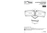
ITEM #0231039
MODEL #GU8002-LED-DC
BATTERY OPERATED LED
MOTION SENSOR LIGHT
Français p. 7
Español p. 13
ATTACH YOUR RECEIPT HERE
AB13434
Serial Number: Purchase Date:
Utilitech & UT Design® and Grounded in Quality® are
registered trademarks of LF, LLC. All Rights Reserved.
Lowes.com
1

PACKAGE CONTENTS
HARDWARE CONTENTS (shown actual size)
PREPARATION
Before beginning assembly of product, make sure all parts are present. Compare parts with
package contents list and diagram above. If any part is missing or damaged, do not attempt to
assemble the product. Contact customer service for replacement parts.
Estimated Assembly Time: 20 minutes
Tools Required for Assembly (not included):
Safety Glasses, Tape Measure, Level, Philips
Screwdriver, Drill Bit, Drill, Step Ladder, Soft Cloth.
A
C
A Fixture 1
PART DESCRIPTION QUANTITY
B Reflector Head 2
C Motion Sensor 1
B
D Rear Housing Cover 1
PART DESCRIPTION QUANTITY
E
Motion Sensor Control Knob
1
F
Dusk-to-Dawn Control Knob
1
Qty. 2
Anchor
BB
Qty. 2
Wood
Screw
AA
ASSEMBLY INSTRUCTIONS
1
1. Unscrew the rear housing cover screw at the bottom of
the fixture (A), until the rear housing cover (D) comes
loose. Note: the rear housing cover screw is designed as
a locking screw and does not come completely out.
Remove the rear housing cover (D).
A
D
D
A
E
F
D
Lowes.com
2

ASSEMBLY INSTRUCTIONS
2. For best results, select a site to mount the fixture 6 to
7 feet above the ground. Do not mount light near other
sources of heat that lie in the detection area (i.e. dryer
exhaust vents, lights, etc.) or reflective surfaces (i.e. pool
water or white walls). Overhanging branches may cause
false activation under extreme conditions. DO NOT
mount behind a window for outdoor detection. Sensor
will not detect heat or motion through glass, clear acrylic
or plastic.
In order to mount the rear housing cover (D), mounting
holes must be drilled out. Place rear housing cover (D)
over the mounting location and mark the center of the
holes to be drilled into the mounting surface. Drill a 1/16
inch pilot hole into the surface. For mounting to concrete
or masonry, install the anchors (BB), by drilling two
3/16-in. pilot holes into the surface. Insert the anchors
(BB) into the holes and tap them into place so they are
flush with the surface. Fasten rear housing cover (D) to
mounting surface with wood screws (AA).
3. Remove the battery compartment door on the fixture
(A) by grasping the catches located on the right and left
sides of the door, and squeeze together until the
catches release the door from the fixture (A).
BB
2
Hardware Used
Anchor
BB
x 2
Wood
Screw
AA
x 2
3
A
4. Insert 4 new alkaline C cell batteries (not included) into
the battery compartment according to the "+" and "-"
markings at the bottom of the battery compartment. Cold
weather can have a negative impact on battery life. Do
not mix old and new batteries.
Re-attach the battery compartment cover by pressing the
cover down over the battery compartment until the cover
"clicks" into place. Note: Batteries will not make proper
contact if the battery compartment cover is not attached
correctly.
4
A
D
D
Lowes.com
3

5
1
2
OPERATING INSTRUCTIONS
ASSEMBLY INSTRUCTIONS
5. Re-attach the LED security light body to the mounted
rear housing cover (D) by angling the bottom away from
the mounted rear housing cover (D) and engaging the
two (2) tabs at the top rear edge of the fixture (A) into the
corresponding openings in the rear housing cover (D).
Once engaged, angle the bottom of the fixture (A) back
toward the rear housing cover (D) and press it against
the rear housing cover (D). While holding it in place,
re-tighten the bottom screw on the fixture (A) until it
engages with the rear housing cover (D), and holds the
fixture (A) in place.
1. The individual reflector heads (B) can be adjusted side
to side and up/down independently to aim the light(s) in
the direction desired. If over time, the up/down
adjustment tension weakens, the hinging action can be
tightened by tightening the screw located below each
head.
2. The motion sensor (C) can be rotated to position
detection field in the direction of an area to be covered. If
the 2 arrow indicators are aligned, the motion sensor (C)
is focused straight ahead. The motion sensor (C) can be
rotated approximately 45 degrees right or left of center to
more precisely focus on a coverage area. The sensor
uses passive infrared technology to detect heat radiation
of moving bodies.The motion sensor has a maximum
detection field of 140° at a distance of 10 feet, 120° at a
distance of 26 feet and 90° at a distance of 39 feet.
3. A built in dusk-to-dawn sensor prevents the fixture (A)
from turning on during the day. The sensitivity of this
sensor can be adjusted by rotating the control knob on
the right side of the sensor lens. Rotating the knob
clockwise toward the sun symbol will decrease the
sensitivity to light, and allow the security light to come on
during while it is still light out. Rotating the knob
counter-clockwise toward the crescent moon symbol
increases the sensitivity to light, and allows the security
light to come on only at night. Setting the knob
somewhere in between adjusts the photo sensor’s
sensitivity to outside light, and is used to trigger the
sensor at different light levels.
A
C
F
C
A
A
A
D
D
3
120°
140°
90°
39.4 ft./12 m
26.2 ft./8 m
10 ft./3 m
Lowes.com
4

OPERATING INSTRUCTIONS
BATTERY REPLACEMENT INSTRUCTIONS
4
4. The motion sensor feature can be adjusted using the
knob on the left side of the light. There are four (4)
settings:
ON- Allows the lights to stay on indefinitely. This setting
should also be used to check the status of the batteries. If
the lights do not come on when set to the ON position, the
batteries need to be replaced. Operating in this mode will
deplete batteries quickly.
FLASH- Allows the lights to flash (ON and OFF) when
motion is sensed, and continue to flash until the security
light no longer senses motion. Note: A flashing light is
more likely to be noticed by neighbors and attract
attention. The lights will turn off approximately 10 seconds
after motion is no longer detected.
10sec- Allows the lights to come on for 10 seconds when
motion is sensed.
OFF- Disables the lights.
1. Unscrew the rear housing cover screw at the bottom
of the fixture (A) until the fixture (A) comes loose. Tilt
the bottom edge of the fixture (A) upward until it
disengages along the top edge. Remove the fixture (A)
from the rear housing cover. Note: the screw does not
fully come out of the opening.
2. Remove the battery compartment door on the fixture
(A) by grasping the catches located on the right and left
sides of the door, and squeeze together until the catches
release the door from the fixture (A). Insert 4 new alkaline
C cell batteries into the battery compartment according to
the "+" and "-" markings at the bottom of the battery
compartment. Do not mix old and new batteries.
Re-attach the battery compartment door by snapping it
back into place using both thumbs to press it down onto
it’s catches. The door will “click” into place. Make sure it
is secure, as the batteries will not make proper contact if
this battery door is not on properly.
3. Re-attach the fixture (A) to the mounted rear
housing cover by angling the bottom away from the
mounted rear housing cover (D), and engaging the
two (2) tabs at the top rear edge of the fixture (A) into
the corresponding openings in the rear housing cover
(D). Once engaged, angle the bottom of the fixture (A)
back toward the rear housing cover (D), and press it
against the rear housing cover (D). While holding it in
place, re-tighten the bottom screw on the fixture (A)
until it engages with the rear housing cover (D), and
holds the fixture (A) in place.
E
C
A
3
A
A
D
D
1
A
D
D
A
2
A
A
ec
Lowes.com
5

You may want to periodically clean the fixture using a mild, non-abrasive glass cleaner and soft
cloth. Do NOT use solvents or cleaners containing abrasive agents. When cleaning the fixture,
make sure you have the power turned off and do not spray liquid cleaner directly onto the bulb,
socket, ballast, or wiring.
CARE AND MAINTENANCE
TROUBLESHOOTING
Minor problems often can be fixed without the help of an electrician. Before doing any work on the
fixture, shut off power supply at the circuit breaker panel to avoid electrical shock.
PROBLEM POSSIBLE CAUSE CORRECTIVE ACTION
1. Batteries are defective.
2. Battery compartment cover
is loose.
3. Batteries installed wrong.
1. Changes in meteorological
conditions.
1. Dusk-to-Dawn setting is set
incorrectly.
2. Setting has been set to “OFF.”
1. Depleted batteries.
2. Momentary heat source or
reflective body.
1. Minor sensor problem.
2. Reflective body in detection
area.
1. Heat source in detection area.
1. Photo sensor is picking up
extraneous light.
1. Replace batteries.
2. Check battery compartment
cover.
3. Install batteries correctly.
1. Adjust sensor’s position.
1. Adjust Dusk-to-Dawn setting.
2. Check setting.
1. Check or replace batteries.
2. Turn sensor detection field away
from source.
1. Remove batteries to reset sensor.
2. Remove reflective body or move
fixture.
1. Remove heat source or move fixture.
1. Reset photo sensor settings.
Fixture doesn’t light.
Detection range
varies from day to day.
Motion sensor activates
during daylight.
Motion sensor does
not activate at all.
Motion sensor
activates at random
or for no reason.
Fixture on all night.
Light flickers on
and off.
Lowes.com
6

REPLACEMENT PARTS LIST
WARRANTY
For replacement parts, call our customer service department at 1-866-994-4148, 8 a.m. - 6 p.m., EST,
Monday - Thursday, 8 a.m. - 5 p.m., EST, Friday.
PART DESCRIPTION PART #
AA Wood Screw HDW8002
BB Anchor HDW8002
AA
AA
BB
BB
The manufacturer warrants this lighting fixture to be free from defects in materials and workmanship
for a period of (3) years from the date of original purchase by the consumer.
We will repair or replace (at our option) the unit in the original color and style if available, or in a
similar color and style if the original item has been discontinued, without charge. The manufacturer
warrants the lamp for 3 years, providing the lamp is not used in a commercial application where it is
on 24 hours per day, but is used in a residential environment for 3 - 5 hours per day. Defective units
must be properly packed and returned to the manufacturer with a letter of explanation and your
original purchase receipt showing date of purchase. Call 1-866-994-4148 to obtain a Return
Authorization number and an address where to ship your defective product. Note: No C.O.D.
shipments will be accepted. The liability of the manufacturer is in any case limited to replacement of
the defective light fixture product. The manufacturer will not be liable for any other loss, damage, or
injury which is caused by the product. This limitation upon the liability of the manufacturer includes
any loss, damage, or injury which is (I) to person or property or otherwise; (II) incidental or
consequential in nature; (III) based upon theories of warranty, contract, negligence, strict liability, tort,
or otherwise; or (IV) directly, or indirectly related to the sale, use, or repair of the product. This
warranty gives you specific rights, and you may also have other rights which vary from state to state.
Printed in China
Utilitech & UT Design® and Grounded in Quality® are
registered trademarks of LF, LLC. All Rights Reserved.
Lowes.com
7
/