Page is loading ...

NOTE: DIAGRAMS & ILLUSTRATIONS ARE NOT TO SCALE.
LENNOX HEARTH PRODUCTS
KITS AND ACCESSORIES
750,202M
REV. NC 02/2006
DECORATIVE UPPER AND LOWER GRILLE KITS
CHARCOAL & SATIN PEWTER
KIT CONTENTS
ITEM QUANTITY DESCRIPTION
1 1 ea. Grill, Upper or Lower
2 1 ea. Instruction Sheet
Table 1 - Refer to Figure 1
UPPER GRILLE KITS - CRESCENTS
Cat. No.# Model Description Model Series
H3541 CUGK35C 35” Charcoal
MPD3530, MPD35ST,
MPB-35ST & EDV3530
H3543 CUGK35SP 35” Satin Pewter
H3549 CUGK40C 40” Charcoal
EDV4035, EDVST,
MPD4035, EBVST
H3551 CUGK40SP 40” Satin Pewter
H3557 CUGK45C 45” Charcoal
EDV4540,
MPD4540
H3559 CUGK45SP 45” Satin Pewter
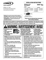
Figure 1
INSTALLATION INSTRUCTIONS FOR UPPER AND LOWER GRILLE KITS
FOR USE WITH LENNOX
™
35/40/45 GAS FIREPLACES
LOWER GRILLE KITS - SUNRISE
Cat. No.# Model Description Model Series
H3569 SLGK35C 35” Charcoal
MPD3530, MPD35ST,
MPB-35ST & EDV3530
H3571 SLGK35SP 35” Satin Pewter
H3577 SLGK40C 40” Charcoal
EDV4035, EDVST,
MPD4035, EBVST
H3579 SLGK40SP 40” Satin Pewter
H3585 SLGK45C 45” Charcoal
EDV4540,
MPD4540
H3587 SLGK45SP 45” Satin Pewter
UPPER GRILLE KITS - SUNRISE
Cat. No.# Model Description Model Series
H3565 SUGK35C 35” Charcoal
MPD3530, MPD35ST,
MPB-35ST & EDV3530
H3567 SUGK35SP 35” Satin Pewter
H3573 SUGK40C 40” Charcoal
EDV4035, EDVST,
MPD4035, EBVST
H3575 SUGK40SP 40” Satin Pewter
H3581 SUGK45C 45” Charcoal
EDV4540,
MPD4540
H3583 SUGK45SP 45” Satin Pewter
LOWER GRILLE KITS - CRESCENTS
Cat. No.# Model Description Model Series
H3545 CLGK35C 35” Charcoal
MPD3530, MPD35ST,
MPB-35ST & EDV3530
H3547 CLGK35SP 35” Satin Pewter
H3553 CLGK40C 40” Charcoal
EDV4035, EDVST,
MPD4035, EBVST
H3555 CLGK40SP 40” Satin Pewter
H3561 CLGK45C 45” Charcoal
EDV4540,
MPD4540
H3563 CLGK45SP 45” Satin Pewter
Sunrise Style (upper grille shown)
Crescent Style (lower grille shown)
Notes:
• The upper and lower grilles are ordered
separately.
• Only the lower grilles include knobs (see 2
knobs shown on Crescent Style, Figure 1).
1
Knobs

NOTE: DIAGRAMS & ILLUSTRATIONS ARE NOT TO SCALE.
Figure 2 - Remove Upper and/or Lower Panel(s)
Top Panel
Removed
Trim Panels will
be either Lou-
vered Panels or
Radiant Panels.
Louvered
Panels
Radiant
Panels
WARNINGS
•
Hot! Do not touch! These decorative grilles
are NOT heat guards. Carefully supervise
children in the same room as appliance.
•
The lower Grille covering the controls will
become hot during operation. Use care when
removing the grille to access the controls and
make sure to place the grille on a surface that
is non-combustible or will not be damaged by
high temperatures.
• INSTALL THIS KIT ONLY WHEN THE FIREPLACE IS OFF
AND COLD!
Read and understand all instructions and warnings in this docu-
ment before beginning the installation.
TOOLS REQUIRED
Phillips Screwdriver
Cutting Pliers
(required for modesty panels with side locating tabs only as
shown in Figure 6)
GENERAL INFORMATION
These decorative grilles are offered in four attractive fi nishes and fi t on the
face of the appliance in place of the standard louvers or radiant panels. If you
encounter any problems, need clarifi cation of these instructions or are not
qualifi ed to properly install this kit, contact you local distributor or dealer.
2
Figure 3 - Remove Hinged Lower Panel
Control Compartment
Access panel
OPENING CONTROL COMPARTMENT DOOR
Control Valve
Lower Control
Compartment Door
Lift the Lower Control Compartment
Door up and pull out to remove.
Up
Out
Hook Catch
Lower Panel - Remove the lower louvered or radiant panel assemby as
follows:
• Hinged Panel (see Figure 3) - Gently depress the outer top corners of
the louvered Control Compartment Access Panel until the spring-loaded
magnetic catches "pop" it free, allowing it to swing out and down to
open. With the panel in the open position, depress the spring-loaded
hinge pin on left side until it disengages from the left cabinet panel
hole. Pull panel away from fi replace.
INSTALLATION INSTRUCTIONS:
1. Remove Louvered or Radiant Panel/Hood Assembly -
Upper Panel - Remove the upper louvered or radiant panel/hood assembly
by pulling the assembly up and out (see Figure 2). In instances where
the radiant panel is used and it is framed in with tile or other approved
material, the hood must still be removed by fi rmly pulling it forward until
it releases from the receiving brackets.
• Hooked Panel (see Figure 4) - Remove the panel by gently lifting it
upward until the hook catches on boths sides clear the locating slots.
Then pull door out to remove.
Figure 4 - Remove Hooked Lower Panel
Hinge Pin
Latch for
Glass Door

3
NOTE: DIAGRAMS & ILLUSTRATIONS ARE NOT TO SCALE.
4. Light the appliance following instrutions on lighting label in control
compartment or see lighting instructions in Homeowner’s Care and
Operation Manual provided with appliance. Ensure that the latch(es)
below the door are engaged with the door’s vee-fl ange and fully closed
before operating the fi replace.
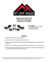
5. Install Grilles (see Figure 7) - Remove the grilles from packaging.
Position the grilles so that the hook catches on the back of grilles slide
into corresponding slots on fi replace.
Magnet
Using a phillips screwdriver, remove the con-
trol compartment magnet (left side only).
Screw
Figure 6 - Remove Magnet
Control Compartment
Figure 7 - Side View of Grilles
Lower Grille
Upper Grille
Knob
Hook
Hook
2. If fi replace has a modesty panel with side locating tabs as shown in
Figure 5, the left tab will require the following modifcation:
a. Remove the modesty panel from the control compartment (see
instructions in Homeowners Care and Operation Manual).
b. Using cutting pliers, cut 1/2” off the end of the left top locating tab
on the modesty panel only as shown in Figure 5.
c. Reinstall modesty panel in fi replace control compartment.
Left Locating Tab on Modesty Panel
Modesty Panel
Modesty Panel
Locating Tab
1/2”
Locating Tab
Modesty Panel
Figure 5 - Cut off End of Left Locating Tab
Cut off end of tab.
3. Remove Magnet in the Control Compartment (if necessary) per
instructions in Figure 6.
Left Locating
Tab

4
NOTE: DIAGRAMS & ILLUSTRATIONS ARE NOT TO SCALE.
Printed in U.S.A. © LENNOX HEARTH PRODUCTS 2006
P/N 750,202M REV. NC 02/2006
Lennox Hearth Products reserves the right to make changes at any time, without notice, in design,
materials, specifi cations, prices and the discontinuance of colors, styles and products. Consult your
local distributor for fi replace code information.
NOTE: DIAGRAMS & ILLUSTRATIONS ARE NOT TO SCALE.
1110 West Taft Avenue • Orange, CA 92865
Figure 8 - COMPLETED INSTALLATION
/