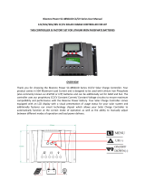
PowerTech MP3745 User manual

Type
User manual

This manual is also suitable for

1
50A
MPPT Solar Charge Controller
for Lithium or SLA Batteries
MP3745
User Manual
2
Contents
I.Mattersneedingattention2
II.Productpicture2,3
III.Descriptionofbasicfunctions3,4
III.DescriptionofLCDscreen4,5
IV.Operationofmachinebuttonsandfunctionintroduction5,6
V.Wirediameterrequirements6
VI.Electricalparameters7
VII.Troubleshooting8
VIII.Customerserviceinformation8
3
I.Mattersneedingattention
1. Keep the product out of reach of children to avoid using it as a toy and causing personal
injury.
Note!
2. Onlyusetheaccessoriesapprovedbythecompanyorfullycomplywiththerequirementsof
thecompanyforthespecificationsoftheaccessories,orelseitmaycausedanger.
3. Operating voltage range of the charger: 12/24/36/48V battery; it will damage the internal
dischargecircuitifthevoltageexceeds75V,sodonotusebatteriesover60V,orelseitmay
damagethecharger.
4. ThemaximumopencircuitvoltageofPVis135V.Donotexceedtherange
duringuse,orelse
thechargermaybedamaged.
5. Do not touch the heat sink in the process of product operation to avoid hot hands. It is
recommendedtousetheproductonthewall.
6. Operatingtemperature:‐10~+40°C.
7. It is strictly forbidden to use in an environment that may be exposed to rain, which may
cause
danger.
4
Productpicture(Fig.1)
II.Functionaldescriptionofeachpartofthepanel(refertoFig.1&
2):
1.UP(upbutton)
2.Down(downbutton)
3.MENU(mainmenubutton)
4.Enter(OKbutton)
5.GreenLEDlight(offwhennocharging,flashingduringcharging,stayonwhenfullycharged).
6.RedLEDlight(RedLEDlight(offwhennoerror,erroralarmwhenthelightis
longon,lithium
batteryonlyhas12Vgear,othergearflashingredlighterror)
7.2*3AUSBoutput
8.LCDscreen
Remark:(Theoperationsofpanelitems14areexplainedbelow).
8
6
7
5
4
3
2
1
5
(Fig.2)
9.Externaltemperatureprobe
10.RJ45port,connectedtotheremotecontrolboardthroughthenetworkcableand
synchronizedwiththeLCDscreen(thisportisreservedandtheremotecontrolboardisoptional)
11.PV+(connectedtothepositiveelectrodeofthesolarpanel)
12.PV‐(connected
tothenegativeelectrodeofthesolarpanel)
13.B+(connectedtothepositiveelectrodeofthebattery)
14.B‐(connectedtothenegativeelectrodeofthebattery)
15.L+(connectedtothepositiveelectrodeoftheload)
16.L‐(connectedtothenegativeelectrodeoftheload)
III.Descriptionofbasicfunctions
1. PV(solarpanelinput):
a. ThemaximumopencircuitvoltageofPVis135V.
b. PVintegratesantireverse(reverseconnectionalarmE8,nocharging,pleaseeliminate
thefault).
c. 12Vbattery,PVinputvoltagerangeis16108V;24Vbattery,PVinputvoltagerangeis
32108V
d. 36Vbattery,PVinputvoltage
rangeis48108V;48Vbattery,PVinputvoltagerangeis
64108V.
2. Batteryoutputfunction
a. Identify12//24/36/48Vbatteryautomatically;themaximumchargingcurrent
is:12/24V/50A,36V/35A,48V/25A.
b. Antireverseconnection(E1alarm).
3. Loadoutputfunction(defaultOFF).
a. Ratedmaximumoutputcurrent50A(12/24/36/48V).
b. Overcurrentprotection>55A.
c. Shortcircuitprotection(E4alarm;pleaseeliminatethefault).
d. Loadoutputover/undervoltageprotection,recoveryvoltage;refertothesetvoltage.
4. Overtemperatureprotection
11 12 13 14 15 16
10
9
6
a. Reduceloadincaseofovertemperature:thechargingcurrentisalways2830Awhen
theheatsinktemperature≥75°C.
b. Recoverwhenloadisreduced:resumenormalcharging(50A)whentheheatsink
temperatureis<70°C.
c. Stopchargingwhentheheatsinktemperatureis≥90°C;resume
chargingwhentheheat
sinktemperatureis<60°C.
5. Externaltemperaturecompensationfunction(onlyfor
AGM/STDbattery)
a.1.Thesystemwillautomaticallyadjustthefloatvoltageaccordingtotheambienttemperature.
Theexternaltemperatureprobeispreferred.Iftheexternaltemperatureprobeisnotconnected
(ortheexternaltemperatureis<40°C),use(temperature≥20°C‐5°C)bydefault.2.Thevoltage
mayvarywhentheinputenergyis
insufficienttostabilizetheenergyrequiredforthefloat
charging.
b.For12/24/36/48Vbatteries,whentheexternalprobetemperature≤0°C~40°C,thefloat
chargingvoltageis14.1/28.2V/42.3V/56.4V
For12/24/36/48Vbatteries,whentheexternalprobetemperatureis0°C~20°C,thefloatcharging
voltageis13.8/27.6V/41.4V/55.2V
For12/24/36/48Vbatteries,whentheexternal
probetemperature≥20°C,thefloatcharging
voltageis13.5/27V/40.5V/54V.
6. WIFInetworkingfunction
a. Theproductmayint egrateWIFImoduleornot.
b. IftheproductintegratesaWIFImodule,youcaninstallthemobileAPP,controltheload
switchthroughtheAPPandviewtheMPPTchargerdatainrealtime,suchasbattery
voltage,chargingcurrent,etc.
7. TheLCDbacklight
isturnedoffifthereisnobuttonoperationin1minute;anybutton
operationwillautomaticallyactivatetheLCDbacklight.
8. a.USBbatteryinputundervoltage/overvoltageprotection(10.5V/60V),batteryinput
undervoltage/overvoltagerecovery(11V/59V);
c. USBoutput2*5V/3A.
7
III.DescriptionofLCDscreen:
ABCDEFG
HIJKLMNOP
A.Sunicon,displayedwhensolarpanelisconnected.
B.Sunlighticon,8intotal,displayaccordingtothechargingcurrent
C.MPPTiconindicatestheMPPTcharger.
D.WIFIicon;turnonWIFIthroughbuttonsettings,readproductdataandcontrolloadoutput
throughAPP.
E.Remotecontrolicon;displayed
whentheremotecontrolisconnected(remotecontrol
optional).
F.Settingsicon;turnonwhenenteringthesettingparameters,andturnoffwhenexit.
D.WIFIicon;WIFION/OFFoptional,defaultON.
F.Batterylevelicon;displaythecorrespondingiconaccordingtothebatteryvoltage.
I.Loadicon;turnon
whentheloadisturnedon,synchronizedwiththeloadswitchON.
J.Connector,three,upcorrespondingtoPV,middlecorrespondingtobattery,down
correspondingtoload.
K.Currentlyidentifiedbatterytype(12/24/36/48V).
L.Protectionicon.Whenthisiconappears,itindicatesthatthemachinehassomeprotection,
suchasload
overcurrent,shortcircuitprotection,undervoltageprotection,etc.(Refertothefault
code).
M.Loadtimingclock2.
N.Loadtimingclock1.
8
O.Daytimeandnighticons;PV>12V,displaydaytimeicon ;PV<12V,displaynighticon after5
minutes.PV<5Vdisplaynighticon immediately.
P. Numericaldisplay(8888characters).Thecurrentdataofthemachinecanbeswitchedbythe
MODEbutton,suchasbatteryvoltage/loadvoltage/PV
voltage/time.
IV.Theoperationofmachinebuttonsisdescribedbelow
UPMENU
DownEnter
1. MENUbuttondescription:
a. Pressindefaultinterfaceafterpoweron:Switchamongbatteryvoltage,loadvoltage,PV
voltageandtimeinterfaceinturn.
b. PressandholdMENUtoentertheparametersettinginterface .Then,pressto
switchamongthe8interfacesinturn.
(1.BatterytypeselectionS(STD),defaultlevel/L(LI)/A(AGM));
(2.WIFIswitchON/OFF,defaultON)
(3.Loadundervoltageprotectionsetting:settingrangeof12Vbatteries:1011.5V,
default10V;settingrangeof24Vbatteries:1823V,default21V;settingrangeof36V
batteries:3034.5,default30V;settingrangeof48V:4046,default40V).
(4.Loadundervoltagerecoverysetting:settingrangeof12Vbatteries:1213V,default
12.5V;settingrangeof24Vbatteries:2426V,default25V;
settingrangeof36V
batteries:3639V,default37.5V;settingrangeof48V:4855V,default50V).
(5.Timesetting:24hoursystem,hour/minutecanbeset).
(6.LOmode:a.Clock1 settingrange0120minutes,default60minutes.b.Clock2
settingrange0120minutes,default30minutes.c.Clock
1triggercondition,when
PVvoltage<10V,outputturnsonafterNminutesloaddelay.d.Clock2triggercondition,
9
when PV>10.5V, the output turns o aer N minutes load delay, so the loop is repeated)
(7. LD mode: The clock seng range is 0-12 hours. a. Clock 1 trigger condion: When
PV<10V, clock 1 turns on the load for N minutes (clock 1 is set to 3 hours by default), and
clock 2 executes following clock 1. b. Clock 2 turns o the load for N minutes (clock 2 is
set to 4 hours by default); c. Aer clock 2 execung, the load is always on unl PV>10.5V,
so the loop is repeated)
(8. TO mode: Set the load mer on/o me; the seng range is 0-24 hours.
a. for example, the default seng: turn on load at 18:00, turn o load at 6:00. The
program automacally turns on/o the load at set me).
Remark:
The load switch mode of items 6-8 is OFF by default. Please turn it on as
needed, and set the required me
c. Press and hold MENU to enter the parameter seng
interface :
1. Press MENU to switch among the 8 interfaces in sequence. 2 Press MENU to cancel
the data that has been modied but hasn’t been saved.
d. Restore the default sengs: first press and hold the MENU buon, then turn on the
power of the baery, and the FFFF icon will be displayed on the screen.
2. UP buon descripon
Enter the parameter seng interface: press: UP / (me plus 1 / voltage plus 0.1V); press
and hold: (me / load voltage) values can be accumulated.
Press in default interface aer power-on: switch among (baery voltage/current), (load
voltage/current) and (PV voltage/current).
3. Down buon descripon
Enter the parameter seng interface and press: DOWN / (me minus 1 / voltage
minus 0.1V); press and hold: (me / load voltage) value can be reduced cumulavely.
Press in default interface aer power-on: Switch among baery current, load current,
and PV current.
4. Enter buon descripon
Press: a. In the parameter seng interface: enter to modify parameters / conrm the
modificaon
b. In the baery voltage interface: load ON/OFF.
V. Wire diameter requirements:
Baery output line: (50A MAX) 6AWG--8AWG; at least 8AWG copper wire, less than 2m.
PV input line: 8AWG--10AWG; professionals can select the appropriate electronic line according
to the actual output PV voltage.
10
PV input Parameters
PV maximum open circuit voltage (VDC) 135V
MPPT voltage (VDC) 16~108V
Maximum PV input power (W)
12V
baery700W; 24 -48Vbaery
1500W;
Maximum MPPT current (12/24V) /50A; 36V/35A;48V/25A
DC output
Baery voltage (VDC) 12//24/36/48V
Baery capacity (AH)
50AH
Output current (A) 50A
Constant voltage charging voltage STD:14.4V/28.8V/43.2V/57.6V
LI:14.5V
AGM:14.6V/29.2V/43.8V/58.4V
Load output
Output voltage (VDC) 12/24/36/48V
Output current (A) 50A/55A
USB output
Output voltage (VDC) 5
Number of USB ports 2
Maximum output current (A) 3.4A Max
Standby current Baery input 12V
Separate MPPT charger < 60 mA
MPPT charger + WIFI module < 160 mA
Protecve funcon
PV/baery input high/low voltage
protecon
Yes
PV/baery reverse connecon protecon Yes
Load overcurrent / short circuit protecon Yes
Temperature protecon Yes (90°C)
Mechanical dimensions
Length X width X height (mm) 238*177*73
Weight 2.3 KG
General data
Operang temperature (°C) - 10~ +40
Cooling method Heat sink
Insulaon class CLASS 1
Protecon level IP30
VI. Electrical Parameters:
11
VII. Fault Codes
E1 reverse connec (please correct)
E2
open circuit prot on ry not connected / or low
voltage
E3
overcurrent prot on (circuit has constant current
the machine may be damaged if there is an error)
E4
Load overcurrent /short circuit protec
(error 10S, turn on the
load
elimina g the error)
E5 overvoltage (ba ery damaged or high ry voltage)
E6 PV (solar) input overvoltage protec on (PV>135V)
E7
Over-temperature protec
, stop charging when heat sink
temperature90°C; resume when temperature60°C
E8 PV reverse conne on (please correct)
ery over and under voltage range
Capacity:12V/24V/36V/48V
low-voltage pr LCD
display:E2
<8/18/27/36V
Capacity:12V/24V/36V/48V
Over voltage protec on LCD
display:E5
>15/31/45/60V
Remark: Please eliminate the fault according to the error code. If the
machine s
does not respond the error is eliminated, it may be
damaged and need
-sales service.
Distributed By:
Electus Distribution Pty. Ltd.
320 Victoria Rd, Rydalmere
NSW 2116 Australia
www.electusdistribution.com.au
  • Page 1 1
  • Page 2 2
  • Page 3 3
  • Page 4 4
  • Page 5 5
  • Page 6 6
  • Page 7 7
  • Page 8 8
  • Page 9 9
  • Page 10 10
  • Page 11 11

PowerTech MP3745 User manual

Type
User manual
This manual is also suitable for

Ask a question and I''ll find the answer in the document

Finding information in a document is now easier with AI