PowerTech MP3743 User manual

Type
User manual

This manual is also suitable for

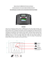
PowerTech MP3743 is a versatile solar charge controller designed for both lithium and SLA batteries, offering advanced charging algorithms and comprehensive protection features. Its intelligent MPPT (Maximum Power Point Tracking) technology optimizes energy harvesting from solar panels, maximizing charging efficiency and minimizing losses. The controller also boasts a range of programmable parameters, allowing you to customize charging and load settings to suit your specific system requirements.

PowerTech MP3743 is a versatile solar charge controller designed for both lithium and SLA batteries, offering advanced charging algorithms and comprehensive protection features. Its intelligent MPPT (Maximum Power Point Tracking) technology optimizes energy harvesting from solar panels, maximizing charging efficiency and minimizing losses. The controller also boasts a range of programmable parameters, allowing you to customize charging and load settings to suit your specific system requirements.

1
50A
MPPT Solar Charge Controller
for Lithium or SLA Batteries
MP3745
User Manual
2
Contents
I.Mattersneedingattention2
II.Productpicture2,3
III.Descriptionofbasicfunctions3,4
III.DescriptionofLCDscreen4,5
IV.Operationofmachinebuttonsandfunctionintroduction5,6
V.Wirediameterrequirements6
VI.Electricalparameters7
VII.Troubleshooting8
VIII.Customerserviceinformation8
3
I.Mattersneedingattention
1. Keep the product out of reach of children to avoid using it as a toy and causing personal
injury.
Note!
2. Onlyusetheaccessoriesapprovedbythecompanyorfullycomplywiththerequirementsof
thecompanyforthespecificationsoftheaccessories,orelseitmaycausedanger.
3. Operating voltage range of the charger: 12/24/36/48V battery; it will damage the internal
dischargecircuitifthevoltageexceeds75V,sodonotusebatteriesover60V,orelseitmay
damagethecharger.
4. ThemaximumopencircuitvoltageofPVis135V.Donotexceedtherange
duringuse,orelse
thechargermaybedamaged.
5. Do not touch the heat sink in the process of product operation to avoid hot hands. It is
recommendedtousetheproductonthewall.
6. Operatingtemperature:‐10~+40°C.
7. It is strictly forbidden to use in an environment that may be exposed to rain, which may
cause
danger.
4
Productpicture(Fig.1)
II.Functionaldescriptionofeachpartofthepanel(refertoFig.1&
2):
1.UP(upbutton)
2.Down(downbutton)
3.MENU(mainmenubutton)
4.Enter(OKbutton)
5.GreenLEDlight(offwhennocharging,flashingduringcharging,stayonwhenfullycharged).
6.RedLEDlight(RedLEDlight(offwhennoerror,erroralarmwhenthelightis
longon,lithium
batteryonlyhas12Vgear,othergearflashingredlighterror)
7.2*3AUSBoutput
8.LCDscreen
Remark:(Theoperationsofpanelitems14areexplainedbelow).
8
6
7
5
4
3
2
1
5
(Fig.2)
9.Externaltemperatureprobe
10.RJ45port,connectedtotheremotecontrolboardthroughthenetworkcableand
synchronizedwiththeLCDscreen(thisportisreservedandtheremotecontrolboardisoptional)
11.PV+(connectedtothepositiveelectrodeofthesolarpanel)
12.PV‐(connected
tothenegativeelectrodeofthesolarpanel)
13.B+(connectedtothepositiveelectrodeofthebattery)
14.B‐(connectedtothenegativeelectrodeofthebattery)
15.L+(connectedtothepositiveelectrodeoftheload)
16.L‐(connectedtothenegativeelectrodeoftheload)
III.Descriptionofbasicfunctions
1. PV(solarpanelinput):
a. ThemaximumopencircuitvoltageofPVis135V.
b. PVintegratesantireverse(reverseconnectionalarmE8,nocharging,pleaseeliminate
thefault).
c. 12Vbattery,PVinputvoltagerangeis16108V;24Vbattery,PVinputvoltagerangeis
32108V
d. 36Vbattery,PVinputvoltage
rangeis48108V;48Vbattery,PVinputvoltagerangeis
64108V.
2. Batteryoutputfunction
a. Identify12//24/36/48Vbatteryautomatically;themaximumchargingcurrent
is:12/24V/50A,36V/35A,48V/25A.
b. Antireverseconnection(E1alarm).
3. Loadoutputfunction(defaultOFF).
a. Ratedmaximumoutputcurrent50A(12/24/36/48V).
b. Overcurrentprotection>55A.
c. Shortcircuitprotection(E4alarm;pleaseeliminatethefault).
d. Loadoutputover/undervoltageprotection,recoveryvoltage;refertothesetvoltage.
4. Overtemperatureprotection
11 12 13 14 15 16
10
9
6
a. Reduceloadincaseofovertemperature:thechargingcurrentisalways2830Awhen
theheatsinktemperature≥75°C.
b. Recoverwhenloadisreduced:resumenormalcharging(50A)whentheheatsink
temperatureis<70°C.
c. Stopchargingwhentheheatsinktemperatureis≥90°C;resume
chargingwhentheheat
sinktemperatureis<60°C.
5. Externaltemperaturecompensationfunction(onlyfor
AGM/STDbattery)
a.1.Thesystemwillautomaticallyadjustthefloatvoltageaccordingtotheambienttemperature.
Theexternaltemperatureprobeispreferred.Iftheexternaltemperatureprobeisnotconnected
(ortheexternaltemperatureis<40°C),use(temperature≥20°C‐5°C)bydefault.2.Thevoltage
mayvarywhentheinputenergyis
insufficienttostabilizetheenergyrequiredforthefloat
charging.
b.For12/24/36/48Vbatteries,whentheexternalprobetemperature≤0°C~40°C,thefloat
chargingvoltageis14.1/28.2V/42.3V/56.4V
For12/24/36/48Vbatteries,whentheexternalprobetemperatureis0°C~20°C,thefloatcharging
voltageis13.8/27.6V/41.4V/55.2V
For12/24/36/48Vbatteries,whentheexternal
probetemperature≥20°C,thefloatcharging
voltageis13.5/27V/40.5V/54V.
6. WIFInetworkingfunction
a. Theproductmayint egrateWIFImoduleornot.
b. IftheproductintegratesaWIFImodule,youcaninstallthemobileAPP,controltheload
switchthroughtheAPPandviewtheMPPTchargerdatainrealtime,suchasbattery
voltage,chargingcurrent,etc.
7. TheLCDbacklight
isturnedoffifthereisnobuttonoperationin1minute;anybutton
operationwillautomaticallyactivatetheLCDbacklight.
8. a.USBbatteryinputundervoltage/overvoltageprotection(10.5V/60V),batteryinput
undervoltage/overvoltagerecovery(11V/59V);
c. USBoutput2*5V/3A.
7
III.DescriptionofLCDscreen:
ABCDEFG
HIJKLMNOP
A.Sunicon,displayedwhensolarpanelisconnected.
B.Sunlighticon,8intotal,displayaccordingtothechargingcurrent
C.MPPTiconindicatestheMPPTcharger.
D.WIFIicon;turnonWIFIthroughbuttonsettings,readproductdataandcontrolloadoutput
throughAPP.
E.Remotecontrolicon;displayed
whentheremotecontrolisconnected(remotecontrol
optional).
F.Settingsicon;turnonwhenenteringthesettingparameters,andturnoffwhenexit.
D.WIFIicon;WIFION/OFFoptional,defaultON.
F.Batterylevelicon;displaythecorrespondingiconaccordingtothebatteryvoltage.
I.Loadicon;turnon
whentheloadisturnedon,synchronizedwiththeloadswitchON.
J.Connector,three,upcorrespondingtoPV,middlecorrespondingtobattery,down
correspondingtoload.
K.Currentlyidentifiedbatterytype(12/24/36/48V).
L.Protectionicon.Whenthisiconappears,itindicatesthatthemachinehassomeprotection,
suchasload
overcurrent,shortcircuitprotection,undervoltageprotection,etc.(Refertothefault
code).
M.Loadtimingclock2.
N.Loadtimingclock1.
8
O.Daytimeandnighticons;PV>12V,displaydaytimeicon ;PV<12V,displaynighticon after5
minutes.PV<5Vdisplaynighticon immediately.
P. Numericaldisplay(8888characters).Thecurrentdataofthemachinecanbeswitchedbythe
MODEbutton,suchasbatteryvoltage/loadvoltage/PV
voltage/time.
IV.Theoperationofmachinebuttonsisdescribedbelow
UPMENU
DownEnter
1. MENUbuttondescription:
a. Pressindefaultinterfaceafterpoweron:Switchamongbatteryvoltage,loadvoltage,PV
voltageandtimeinterfaceinturn.
b. PressandholdMENUtoentertheparametersettinginterface .Then,pressto
switchamongthe8interfacesinturn.
(1.BatterytypeselectionS(STD),defaultlevel/L(LI)/A(AGM));
(2.WIFIswitchON/OFF,defaultON)
(3.Loadundervoltageprotectionsetting:settingrangeof12Vbatteries:1011.5V,
default10V;settingrangeof24Vbatteries:1823V,default21V;settingrangeof36V
batteries:3034.5,default30V;settingrangeof48V:4046,default40V).
(4.Loadundervoltagerecoverysetting:settingrangeof12Vbatteries:1213V,default
12.5V;settingrangeof24Vbatteries:2426V,default25V;
settingrangeof36V
batteries:3639V,default37.5V;settingrangeof48V:4855V,default50V).
(5.Timesetting:24hoursystem,hour/minutecanbeset).
(6.LOmode:a.Clock1 settingrange0120minutes,default60minutes.b.Clock2
settingrange0120minutes,default30minutes.c.Clock
1triggercondition,when
PVvoltage<10V,outputturnsonafterNminutesloaddelay.d.Clock2triggercondition,
9
when PV>10.5V, the output turns o aer N minutes load delay, so the loop is repeated)
(7. LD mode: The clock seng range is 0-12 hours. a. Clock 1 trigger condion: When
PV<10V, clock 1 turns on the load for N minutes (clock 1 is set to 3 hours by default), and
clock 2 executes following clock 1. b. Clock 2 turns o the load for N minutes (clock 2 is
set to 4 hours by default); c. Aer clock 2 execung, the load is always on unl PV>10.5V,
so the loop is repeated)
(8. TO mode: Set the load mer on/o me; the seng range is 0-24 hours.
a. for example, the default seng: turn on load at 18:00, turn o load at 6:00. The
program automacally turns on/o the load at set me).
Remark:
The load switch mode of items 6-8 is OFF by default. Please turn it on as
needed, and set the required me
c. Press and hold MENU to enter the parameter seng
interface :
1. Press MENU to switch among the 8 interfaces in sequence. 2 Press MENU to cancel
the data that has been modied but hasn’t been saved.
d. Restore the default sengs: first press and hold the MENU buon, then turn on the
power of the baery, and the FFFF icon will be displayed on the screen.
2. UP buon descripon
Enter the parameter seng interface: press: UP / (me plus 1 / voltage plus 0.1V); press
and hold: (me / load voltage) values can be accumulated.
Press in default interface aer power-on: switch among (baery voltage/current), (load
voltage/current) and (PV voltage/current).
3. Down buon descripon
Enter the parameter seng interface and press: DOWN / (me minus 1 / voltage
minus 0.1V); press and hold: (me / load voltage) value can be reduced cumulavely.
Press in default interface aer power-on: Switch among baery current, load current,
and PV current.
4. Enter buon descripon
Press: a. In the parameter seng interface: enter to modify parameters / conrm the
modificaon
b. In the baery voltage interface: load ON/OFF.
V. Wire diameter requirements:
Baery output line: (50A MAX) 6AWG--8AWG; at least 8AWG copper wire, less than 2m.
PV input line: 8AWG--10AWG; professionals can select the appropriate electronic line according
to the actual output PV voltage.
10
PV input Parameters
PV maximum open circuit voltage (VDC) 135V
MPPT voltage (VDC) 16~108V
Maximum PV input power (W)
12V
baery700W; 24 -48Vbaery
1500W;
Maximum MPPT current (12/24V) /50A; 36V/35A;48V/25A
DC output
Baery voltage (VDC) 12//24/36/48V
Baery capacity (AH)
50AH
Output current (A) 50A
Constant voltage charging voltage STD:14.4V/28.8V/43.2V/57.6V
LI:14.5V
AGM:14.6V/29.2V/43.8V/58.4V
Load output
Output voltage (VDC) 12/24/36/48V
Output current (A) 50A/55A
USB output
Output voltage (VDC) 5
Number of USB ports 2
Maximum output current (A) 3.4A Max
Standby current Baery input 12V
Separate MPPT charger < 60 mA
MPPT charger + WIFI module < 160 mA
Protecve funcon
PV/baery input high/low voltage
protecon
Yes
PV/baery reverse connecon protecon Yes
Load overcurrent / short circuit protecon Yes
Temperature protecon Yes (90°C)
Mechanical dimensions
Length X width X height (mm) 238*177*73
Weight 2.3 KG
General data
Operang temperature (°C) - 10~ +40
Cooling method Heat sink
Insulaon class CLASS 1
Protecon level IP30
VI. Electrical Parameters:
11
VII. Fault Codes
E1 reverse connec (please correct)
E2
open circuit prot on ry not connected / or low
voltage
E3
overcurrent prot on (circuit has constant current
the machine may be damaged if there is an error)
E4
Load overcurrent /short circuit protec
(error 10S, turn on the
load
elimina g the error)
E5 overvoltage (ba ery damaged or high ry voltage)
E6 PV (solar) input overvoltage protec on (PV>135V)
E7
Over-temperature protec
, stop charging when heat sink
temperature90°C; resume when temperature60°C
E8 PV reverse conne on (please correct)
ery over and under voltage range
Capacity:12V/24V/36V/48V
low-voltage pr LCD
display:E2
<8/18/27/36V
Capacity:12V/24V/36V/48V
Over voltage protec on LCD
display:E5
>15/31/45/60V
Remark: Please eliminate the fault according to the error code. If the
machine s
does not respond the error is eliminated, it may be
damaged and need
-sales service.
Distributed By:
Electus Distribution Pty. Ltd.
320 Victoria Rd, Rydalmere
NSW 2116 Australia
www.electusdistribution.com.au
  • Page 1 1
  • Page 2 2
  • Page 3 3
  • Page 4 4
  • Page 5 5
  • Page 6 6
  • Page 7 7
  • Page 8 8
  • Page 9 9
  • Page 10 10
  • Page 11 11

PowerTech MP3743 User manual

Type
User manual
This manual is also suitable for

PowerTech MP3743 is a versatile solar charge controller designed for both lithium and SLA batteries, offering advanced charging algorithms and comprehensive protection features. Its intelligent MPPT (Maximum Power Point Tracking) technology optimizes energy harvesting from solar panels, maximizing charging efficiency and minimizing losses. The controller also boasts a range of programmable parameters, allowing you to customize charging and load settings to suit your specific system requirements.

Ask a question and I''ll find the answer in the document

Finding information in a document is now easier with AI