Page is loading ...

Libretto L100/L105/Satellite UX/TOSHIBA NB100 Maintenance Manual
Toshiba Personal Computer
TOSHIBA NB100
(PLL10X-XXXXX)
Maintenance Manual
TOSHIBA CORPORATION
S/ No

ii TOSHIBA NB100 Maintenance Manual
Copyright
© 2008 by Toshiba Corporation. All rights reserved. Under the copyright laws, this manual
cannot be reproduced in any form without the prior written permission of Toshiba. No patent
liability is assumed with respect to the use of the information contained herein.
TOSHIBA NB100 Maintenance Manual
First edition Sep 2008
Disclaimer
The information presented in this manual has been reviewed and validated for accuracy. The
included set of instructions and descriptions are accurate for the TOSHIBA NB100 at the
time of this manual's production. However, succeeding computers and manuals are subject
to change without notice. Therefore, Toshiba assumes no liability for damages incurred
directly or indirectly from errors, omissions, or discrepancies between any succeeding
product and this manual.
Trademarks
Intel and Pentium are registered trademarks of Intel Corporation.
IBM, IBM PC/XT, PC/AT, PS/2 and OS/2 are registered trademarks of IBM Corporation.
Windows XP are registered trademarks of Microsoft Corporation.
Sound Blaster and Pro are trademarks of Creative Technology Ltd.
UNIX is a registered trademark of X/Open Company Ltd.
NetWare are registered trademarks of Novell, Inc.
All other properties are trademarks or registered trademarks of their respective holders.

TOSHIBA NB100 Maintenance Manual iii
Preface
This maintenance manual describes how to perform hardware service maintenance for the
Toshiba Personal Computer TOSHIBA NB100 , referred to as TOSHIBA NB100 in this
manual.
The procedures described in this manual are intended to help service technicians isolate
faulty Field Replaceable Units (FRUs) and replace them in the field.
SAFETY PRECAUTIONS
Four types of messages are used in this manual to bring important information to your
attention. Each of these messages will be italicized and identified as shown below.
DANGER: “Danger” indicates the existence of a hazard that could result in death or
serious bodily injury, if the safety instruction is not observed.
WARNING: “Warning” indicates the existence of a hazard that could result in bodily
injury, if the safety instruction is not observed.
CAUTION: “Caution” indicates the existence of a hazard that could result in property
damage, if the safety instruction is not observed.
NOTE: “Note” contains general information that relates to your safe maintenance
service.
Improper repair of the computer may result in safety hazards. Toshiba requires service
technicians and authorized dealers or service providers to ensure the following safety
precautions are adhered to strictly.
Be sure to fasten screws securely with the right screwdriver. If a screw is not fully
fastened, it could come loose, creating a danger of a short circuit, which could cause
overheating, smoke or fire.
If you replace the battery pack, RTC battery or backup battery, be sure to use only the
same model battery or an equivalent battery recommended by Toshiba. Installation of
the wrong battery can cause the battery to explode.

iv TOSHIBA NB100 Maintenance Manual
The manual is divided into the following parts:
Chapter 1 Hardware Overview describes the TOSHIBA NB100 system unit and
each FRU.
Chapter 2 Troubleshooting Procedures explains how to diagnose and resolve
FRU problems.
Chapter 3 Test and Diagnostics describes how to perform test and diagnostic
operations for maintenance service.
Chapter 4 Replacement Procedures describes the removal and replacement of the
FRUs.
Appendices The appendices describe the following:
Handling the LCD module
Board layout
Pin Assignments
Keyboard scan/character codes
Key layout

TOSHIBA NB100 Maintenance Manual v
Conventions
This manual uses the following formats to describe, identify, and highlight terms and
operating procedures.
Acronyms
On the first appearance and whenever necessary for clarification acronyms are enclosed in
parentheses following their definition. For example:
Read Only Memory (ROM)
Keys
Keys are used in the text to describe many operations. The key top symbol as it appears on
the keyboard is printed in boldface type.
Key operation
Some operations require you to simultaneously use two or more keys. We identify such
operations by the key top symbols separated by a plus (+) sign. For example, Ctrl + Pause
(Break) means you must hold down Ctrl and at the same time press Pause (Break). If
three keys are used, hold down the first two and at the same time press the third.
User input
Text that you are instructed to type in is shown in the boldface type below:
DISKCOPY A: B:
The display
Text generated by the XXXXX that appears on its display is presented in the type face
below:
Format complete
System transferred

4 Replacement Procedures
TOSHIBA NB100 Maintenance Manual 4-iii
Table of Contents
Chapter 1 Hardware Overview
1.1 Features ......................................................................................................................5
1.2 System Unit Components.........................................................................................11
1.3 2.5-inch HDD...........................................................................................................16
1.4 Solid State Drive (SSD) ...........................................................................................17
1.5 Power Supply ...........................................................................................................18
1.6 Batteries....................................................................................................................19
1.6.1 Main Battery...........................................................................................19
1.6.2 Battery Charging Control.......................................................................19
1.6.3 RTC Battery ...........................................................................................20
Chapter 2 Troubleshooting
2.1 Outline....................................................................................................................2-1
2.2 Basic Flowchart......................................................................................................2-2
2.3 Power Supply .........................................................................................................2-6
Procedure 1 Power Icon Check...........................................................................2-6
Procedure 2 Connection Check........................................................................... 2-8
Procedure 3 Replacement Check........................................................................2-8
2.4 System Board .........................................................................................................2-9
Procedure 3 Replacement Check....................................................................2-10
2.5 HDD ..................................................................................................................... 2-11
Procedure 1 Message Check.............................................................................2-11
Procedure 2 Partition Check ......................................................................2-11
Procedure 3 Format Check..........................................................................2-12
Procedure 4 Test Program Check ...............................................................2-13
Procedure 5 Connector Check and Replacement Check.............................2-14
2.6 Keyboard..............................................................................................................2-15
Procedure 1 Test Program Check ......................................................................2-15

4 Replacement Procedures
4-iv TOSHIBA NB100 Maintenance Manual
Procedure 2 Connector Check and Replacement Check....................................2-15
2.7 Display .................................................................................................................2-16
Procedure 1 External Monitor Check .........................................................2-16
Procedure 2 Test Program Check ...............................................................2-16
Procedure 3 Connector Check and Replacement Check.............................2-16
2.8 LAN......................................................................................................................2-18
Procedure 1 Test Program Check ...............................................................2-18
Procedure 2 Connector Check and Replacement Check.............................2-18
2.9 Audio Test............................................................................................................2-18
Procedure 1 Test Program Check ......................................................................2-19
Procedure 2 Connector Check and Replacement Check....................................2-19
2.10 Cooling Module....................................................................................................2-20
Procedure 1 Test Program Check ...............................................................2-20
Procedure 2 Connector Check and Replacement Check.............................2-20
Chapter 3 Diagnostic Programs
3.1 General .....................................................................Error! Bookmark not defined.
3.2 Quick Start................................................................Error! Bookmark not defined.
3.2.1 Quick Test ..............................................Error! Bookmark not defined.
3.2.2 Customization Test.................................Error! Bookmark not defined.
3.2.3 Keyboard Layout test .............................Error! Bookmark not defined.
3.2.4 Audio Play Test......................................Error! Bookmark not defined.
3.2.5 Audio Record Test .................................Error! Bookmark not defined.
3.2.6 DMI Read...............................................Error! Bookmark not defined.
3.2.7 DMI Write..............................................Error! Bookmark not defined.
3.2.8 System Information................................Error! Bookmark not defined.
3.2.9 View Logs ..............................................Error! Bookmark not defined.
3.2.10 Exit to Free DOS...................................Error! Bookmark not defined.
3.2.11 The Diagnostics Screen Explanation......Error! Bookmark not defined.
3.3 Options .....................................................................Error! Bookmark not defined.
3.3.1 Overview................................................Error! Bookmark not defined.
3.3.2 Batch Parameters Configuration ............Error! Bookmark not defined.

4 Replacement Procedure
iv TOSHIBA NB100 Maintenance Manual
3.3.3 Item’s Parameters Configuration ...........Error! Bookmark not defined.
3.3.4 Load Batch Parameters...........................Error! Bookmark not defined.
3.3.5 Save Batch Parameters...........................Error! Bookmark not defined.
3.3.6 LOG Parameters Setting.........................Error! Bookmark not defined.
3.3.7 Specify LOG Viewer..............................Error! Bookmark not defined.
3.3.8 Display LOG File...................................Error! Bookmark not defined.
3.3.9 LOG Viewer...........................................Error! Bookmark not defined.
3.3.10 LOG File Sample ...................................Error! Bookmark not defined.
3.4 Subtests.....................................................................Error! Bookmark not defined.
3.5 System Test..............................................................Error! Bookmark not defined.
3.6 Memory Test............................................................Error! Bookmark not defined.
3.7 Storage......................................................................Error! Bookmark not defined.
3.8 Video........................................................................Error! Bookmark not defined.
3.9 Communication (COMM)........................................Error! Bookmark not defined.
3.10 Peripheral .................................................................Error! Bookmark not defined.
3.11 Error Codes and description.....................................Error! Bookmark not defined.
3.12 Quick Test Item List.................................................Error! Bookmark not defined.
Chapter 4 Replacement Procedures
4.1 General...................................................................................................................4-1
Safety Precautions................................................................................................4-2
Before You Begin................................................................................................4-4
Disassembly Procedures ......................................................................................4-5
Assembly Procedures...........................................................................................4-5
Tools and Equipment...........................................................................................4-6
Screw Tightening Torque ....................................................................................4-6
Colors of Screw Shanks.......................................................................................4-7
Symbols of Screws on the Computer Body.........................................................4-7
Symbol examples.................................................................................................4-7
Removing the Battery Pack .................................................................................4-8
Installing the Battery Pack...................................................................................4-9
Removing the Momery Card .............................................................................4-10

4 Replacement Procedures
4-iv TOSHIBA NB100 Maintenance Manual
Installing the Momery Card...............................................................................4-11
Removing the Optional Memory.......................................................................4-12
Installing the Optional Memory.........................................................................4-13
4.2 Keyboard Cover and Keyboard............................................................................4-14
Removing the Keyboard Cover and Keyboard..................................................4-14
Installing the Keyboard Cover and Keyboard ...................................................4-16
4.3 Wireless LAN Card..............................................................................................4-17
Removing the Wireless LAN Card....................................................................4-17
Installing the Wireless LAN Card......................................................................4-18
4.4 Display Assembly.....................................................................................................4-19
Removing the Display Assembly.......................................................................4-19
Installing the Display Assembly........................................................................4-21
4.5 Top Cover.............................................................................................................4-22
Removing the Top Cover...................................................................................4-22
Installing the Top Cover ....................................................................................4-23
4.6 SSD/HDD and Fan...............................................................................................4-24
Removing the SSD/HDD and Fan.....................................................................4-24
Installing the SSD/HDD and Fan.......................................................................4-26
4.7 System Board,DC-IN,RJ45 Cable and Blue-Tooth Card.....................................4-27
Removing the System Board,DC-IN,RJ45 Cable and Blue-Tooth Card….......4-27
Installing the System Board,DC-IN,RJ45 Cable and Blue-Tooth Card............4-29
4.8 Display Mask........................................................................................................4-30
Removing the LCD Display Mask.....................................................................4-30
Installing the LCD Display Mask......................................................................4-32
4.9 LCD Modules.......................................................................................................4-33
Removing the LCD module ..............................................................................4-33
Installing the LCD Module................................................................................4-35
4.10 CCD board and Speakers .....................................................................................4-36
Removing the CCD board and Speakers ...........................................................4-36
Installing the CCD board and Speakers.............................................................4-37
4.11 Touch Pad Board..................................................................................................4-38
Removing the Touch Pad Board........................................................................4-38

4 Replacement Procedure
vi TOSHIBA NB100 Maintenance Manual
Installing the Touch Pad Board .........................................................................4-39

4 Replacement Procedures
4-iv TOSHIBA NB100 Maintenance Manual
Appendices
Appendix A Handling the LCD Module ...........................................................................A-1
Appendix B Board Layout ................................................................................................ B-1
Appendix C Pin Assignments............................................................................................ C-1
Appendix D Keyboard Scan/Character Codes ..................................................................D-1
Appendix E Key Layout.....................................................................................................E-1

Chapter 1
Hardware Overview
TOSHIBA NB100 Maintenance Manual i

1 Hardware Overview
ii TOSHIBA NB100 Maintenance Manual

1 Hardware Overview
TOSHIBA NB100 Maintenance Manual iii
Chapter 1 Contents
1.1 Features......................................................................................................................... 5
1.2 System Unit Components ........................................................................................... 11
1.3 2.5-inch HDD.............................................................................................................. 16
1.4 Solid State Drive (SSD).............................................................................................. 17
1.5 Power Supply.............................................................................................................. 18
1.6 Batteries ...................................................................................................................... 19
1.6.1 Main Battery.......................................................................................... 19
1.6.2 Battery Charging Control...................................................................... 19
1.6.3 RTC Battery .......................................................................................... 20

1 Hardware Overview
iv TOSHIBA NB100 Maintenance Manual
Figures
Figure 1-1 ID Parts Description Placement...............................................................................8
Figure 1-2 Computer Block Diagram........................................................................................9
Figure 1-3 System Board Configurations................................................................................10
Figure 1-4 System Unit Block Diagram..................................................................................11
Figure 1-5 SATA HDD ...........................................................................................................16
Figure 1-6 Solid state driver....................................................................................................17
Table
Table 1-1 HDD Specifications ................................................................................................16
Table 1-2 SSD Specifications..................................................................................................17
Table 1-3 Battery specifications..............................................................................................19
Table 1-4 Quick/Normal charging time ..................................................................................19

1.1 Features 1 Hardware Overview
TOSHIBA NB100 Maintenance Manual 5
1.1 Features
The Toshiba Arizona is a B5 size notebook PC based on the ATOM processor, providing high-
speed processing capabilities and advanced features. The computer employs a Lithium Ion
battery that allows it to be battery-operated for a longer period of time. The display uses 8.9-
inch WSGA LCD panel, at a resolution of 1280 by 600 pixels...
The computer has the following features.
Processor
The CPU is the ATOM Processor.
Diamondville 1.6GHz
Host Bridge System Controller
System Controller: Intel 945GSE+ICH7-M
Graphics
Intel 945GSE integrated graphic.
Memory
The computer has one SO-DIMMs slot comes standard with DDRII-667/800MHz
module. It supports PC2-5300/6400 and uses SO-DIMMs (DDRII SDRAM) driven at
1.8 V, accepting BTO/CTO for your memory requirements. It can incorporate up to 1
GB for 945GSE.
Using the following sizes of memory modules:
y 512 MB (64M×16×4P)/667 MHZ
y 1024 MB (64M×16×8P)/800 MHZ
Hard Disk Drive (HDD)
The computer accommodates 9.5 mm height HDD with following storage capacities:
y 80 GB (9.5 mm thick) SATA (5,400rpm)
y 120 GB (9.5 mm thick) SATA (5,400rpm)

1 Hardware Overview 1.1 Features
6 TOSHIBA NB100 Maintenance Manual
y 160 GB (9.5 mm thick) SATA (5,400rpm)
Solid-State Drive (SSD)
The computer accommodates SSD with following storage capacities:
y 4 GB SATA
Display
The LCD displays available come with one of following types:
y 8.9” WSGA LED backlight color display, resolution 1280×600
Keyboard
The keyboard has 11 kinds’ countries key.
Battery
The computer has a removable 4 Cell Lithium Ion battery pack.
Universal Serial Bus (USB) Ports
The computer has four USB 2.0 ports. It is supported to daisy-chain a maximum of 127
USB devices. The serial data transfer rate is 480 Mbps or 12 Mbps and 1.5 Mbps. These
ports support PnP installation and hot plugging.
External Monitor Port
A 15-pin external monitor port is provided, through which the computer automatically
recognizes an external VESA DDC 2B compatible monitor.
Multiple Digital Media Card Slot
This computer is equipped with Multiple Digital Media Card Slot that can accommodate
SD/ Mini-SD/ Micro-SD/ SD-IO/ SDHC/ MS/ MS Pro/ MMC memory cards. This slot is
for your memory card requirements to provide memory card read on your computer
Toshiba Pointing Device
Toshiba Pointing Device has one kind of Normal touchpad and one kind of touch pad.

1.1 Features 1 Hardware Overview
TOSHIBA NB100 Maintenance Manual 7
Sound System
The ALC262 integrated audio controller supports multimedia. The sound system
contains the following:
y Stereo speakers
y Headphone / SPDIF combo jack
y Internal microphone
y External microphone jack
LAN
The internal LAN board supports 10/100Mbit. It also supports Wake-up on LAN from
S3/S4/S5 and PXE boot support. The LAN board has RJ45 jack to directly accommodate
a LAN cable.
Wireless LAN
The internal Mini Card slot supports IEEE802.11bg. The Antenna has two dual band
antennas.
Internal Camera (BTO)
The computer has an internal camera. The camera has VGA (fixed focus) for low end
ID or 1.3Mpix resolution (fixed focus) for mainstream ID support.

1 Hardware Overview 1.1 Features
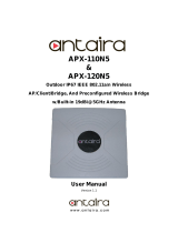
Figures 1-1/1-2/1-3 and 1-4 show the computer and its system unit configuration,
respectively.
Figure 1-1 ID Parts Description Placement
8 TOSHIBA NB100 Maintenance Manual

1.1 Features 1 Hardware Overview
Figure 1-2 Computer Block Diagram
TOSHIBA NB100 Maintenance Manual 9
/