Page is loading ...

Plumbers' Putty or CaulkingAdjustable Wrench Phillips ScrewdriverChannel Locks
TOOLS REQUIRED
SPREAD
LAVATORY
FAUCET
Installation
Instructions
M968211
Certified to comply with ANSI A112.18.1M
1
SPOUT ASSEMBLY
4
2
6
1
3
VALVE INSTALLATION
2
5/16'' MIN.
Insert VALVE BODY (1) through hole from underside
of SINK (2). Threads of VALVE BODY (1) should extend
at least 5/16 inch above SINK (2) top. If necessary,
adjust LOCKNUT (3). Make sure RUBBER WASHER (6)
is installed.
Place RUBBER RING (4) on SINK (2) and screw DECK
ADAPTER (5) onto VALVE BODY (1) until snug against
internal stop.
Set VALVE BODIES (1,1A) so that their outlets are
facing toward center of sink and then tighten LOCKNUT
(3) using WRENCH (7) supplied with faucet.
7
3
TEE AND HOSE INSTALLATION
2881
Thank you for selecting American-Standard...the benchmark of fine
quality for over 100 years.
To ensure that your installation proceeds smoothly--please read these
instructions carefully before you begin.
Connect TEE (1) to SPOUT SHANK (2). Tighten COUPLING
NUT (3).
Connect COUPLING NUTS (4) of HOSE to each valve outlet and
tighten securely.
1
3
2
4
HOSE
Insert SPOUT SHANK (1) through center
hole of SINK (2). Make sure RING
WASHER (3) is properly positioned
into SPOUT BASE.
Assemble RUBBER WASHER (4),
BRASS WASHER (5) and LOCKNUT (6)
onto threads of SPOUT SHANK (1)
from underside of SINK (2).
Insert LIFT ROD (7) through SPOUT (8)
and slot of BRASS WASHER (5).
Align SPOUT (8) and tighten LOCKNUT (6).
Be sure slot in BRASS WASHER (5) is
positioned to the rear as shown.
7
8
1
3
4
6
5
SLOT
2
5
Turn off hot and cold water supplies before beginning.
CAUTION
HOT LINE FOR HELP
For toll-free information and answers to your questions, call:
1 (800) 223-0068
Weekdays 8:00 a.m. to 8:00 p.m. EST
IN CANADA 1-800-387-0369 (TORONTO 1-905-306-1093)
Weekdays 8:00 a.m. to 7:00 p.m. EST
Product names listed herein are trademarks of American Standard Inc.
© American Standard Inc. 2002
by
COLLECTION
™
“”
THE
VALVE
OUTLET

6
TEST INSTALLED FITTING
With HANDLES (1) in OFF position, turn on WATER SUPPLIES (2)
and check all connections for leaks.
Remove AERATOR (3).
Operate both HANDLES to flush water lines thoroughly.
Replace AERATOR (3).
1
2
3
M968211
4
3
MAKE WATER SUPPLY CONNECTIONS
Connect water supply to FAUCET (1) with 1/2" IPS
FLEXIBLE SUPPLIES (3) or 3/8" O.D. BULL-NOSE RISERS (4).
Use wrench to tighten connections.
Do not over tighten. Be careful not to kink copper supply when
bending. Use tubing cutter to cut to proper length.
1
4
FERRULE
NOTE: FLEXIBLE SUPPLIES OR BULL-NOSE RISERS MUST BE
PURCHASED SEPARATELY.
COUPLING
NUT
5
1
2
TOP
Figure "A"
SPLINE END DOWN
INSTALL HANDLES
4
3
7
5
6
Push INDEX CAP (6) in hole of HANDLE (4).
Secure HANDLE (4) with HANDLE SCREW (5).
Find correct position of HANDLE (4) by adjusting male teeth on
ADAPTER (1) to female teeth in HANDLE (4).
Thread HANDLE BASE (3) onto DECK ADAPTER (7)
Push HANDLE (4) onto ADAPTER (1).
Push ADAPTER (1) on VALVE STEM (2), so that the hole of the
ADAPTER (1) without spline is facing up. See figure "A".

9
SERVICE
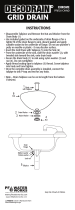
INSTALL POP-UP DRAIN
7
1
2
A
3
4
5
10
11
12
8
G
D
E
6
7
F
C
9
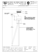
Push Tail piece (11) down into Trap (C) (threaded end up).
Assemble Pivot Rod (9) as shown in Figure-4B. Notice the
position of the Concave Washer (G).
Insert Pivot Rod (9) into Drain Body (10) and tighten Pivot
Nut (F).
Thread Locknut (5), Washer (4) and Gasket (3) (Bevel side
up) onto Drain Body (10).
Apply a bead of Putty (D) to underside of Flange (2).
Remove one end of Clip (8) from Pivot Rod (9) by squeezing
ends together while sliding.
Insert Pivot Rod (9) into second or third hole in Extension
Rod (7) and reassemble Clip (8).
Adjust stopper height by repositioning Extension Rod (7) and
tightening Thumbscrew (6).
Feed Drain Body (10) up through Sink (A) and thread the
Flange (2) fully onto Drain Body (10).
Tighten Locknut (5) firmly, keeping the pivot rod hole pointed
towards the back of the sink.
Drop Stopper (1) into Drain Body (10).
Position Extension Rod (7) onto Pop-Up Rod (E) and tighten
Thumbscrew (6).
1-1/4"
FIGURE-4B:
Push TAILPIECE INSERT (12) into TAILPIECE (11) and push
TAILPIECE up and thread tightly into DRAIN BODY (10).
F
8
CHECK DRAIN CONNECTIONS
1
2
3
Operate Lift Rod and fill lavatory with water. Check that
DRAIN STOPPER (1) makes a good seal and retains water
in lavatory. Adjust stopper height by repositioning Lift
Rod (2) and tightening Thumbscrew (3).
Release DRAIN STOPPER (1) and check all drain
connections and "P" trap for leaks. Tighten if necessary.
10
CARE INSTRUCTIONS:
DO: SIMPLY RINSE THE PRODUCT
CLEAN WITH CLEAR WATER. DRY
WITH A SOFT COTTON FLANNEL
CLOTH.
DO NOT: CLEAN THE PRODUCT
WITH SOAPS, ACID, POLISH,
ABRASIVES, HARSH CLEANERS,
OR A CLOTH WITH A COARSE
SURFACE.
"O" RING
M968211
To change direction of handle rotation,
proceed as follows:
Turn valve to OFF position.
Pull out INDEX CAP (1) and remove
HANDLE SCREW (2).
Pull off HANDLE (3), and unscrew
ESCUTCHEON (4).
Pull off STEM ADAPTER (7).
Remove SPRING CLIP (6).
Lift STOP WASHER (5), turn 90° and replace.
Replace SPRING CLIP (6) and STEM ADAPTER (7).
Reinstall ESCUTCHEON (4) and HANDLE
ASSEMBLY (1,2 & 3).
If spout drips, operate handles several times
from OFF to ON position. Do not force - handles
turn only 90°.
90°
5
6
2
4
3
7
1
/