Metra Electronics 99-8218 User manual
- Category
- Motor vehicle electronics
- Type
- User manual

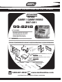
INSTALLATION INSTRUCTIONS FOR PART 99-8218
Phillips Screwdriver • Socket
1-800-221-0932 www.metraonline.com
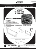
KIT FEATURES
© COPYRIGHT 2004-2010 METRA ELECTRONICS CORPORATION
• DIN Radio Provision with Pocket
• ISO Radio Provision with Pocket
• Double DIN Radio Provision
• Stacked ISO Units Provision
99-8218
APPLICATIONS
A) Radio Housing • B) Radio Housing Brackets • C) ISO Snap-In Brackets • D) Double DIN Brackets
KIT COMPONENTS
C
E) Trim Plate • F) Double DIN Trim Plate • G) Pocket • H) (4) # 8 x 3/8 Phillips Screws • I) (4) #4 x 1/4 Phillips Screws
B
D
E
F
G
H
I
Small Flat Blade Screwdriver or
Panel Removal Tool
TOYOTA
CAMRY / CAMRY HYBRID
2007-2011
A
WIRING AND ANTENNA CONNECTIONS (Sold Separately)
Wir
e harness:
• 70-1761 Toyota 1987-up
• TYTO-01 Toyota amp interface harness 2003-up
Antenna adapter:
• Not required
TOOLS REQUIRED:

Dash Disassembly
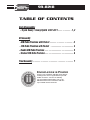
- Toyota Camry / Camry Hybrid 2007-2011 . . . . . . . . . . . . 1, 2
Kit
Assembly
- DIN Radio Provision with Pocket . . . . . . . . . . . . . . . . . . . . . 3
- ISO Radio Provision with Pocket . . . . . . . . . . . . . . . . . . . . . 4
- Double DIN Radio Provision . . . . . . . . . . . . . . . . . . . . . . . . . . 5
- Stacked ISO Units Provision . . . . . . . . . . . . . . . . . . . . . . . . . . 6
Final
Assembly ....................................7
TABLE OF CONTENTS
99-8218
K
NOWLEDGE IS
P
OWER
Enhance your installation and fabrication skills by
enrolling in the most recognized and respected
mobile electronics school in our industry.
Log onto www.installerinstitute.com or call
800-354-6782 for more information and take
steps toward a better tomorrow.

1
99-8218
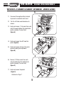
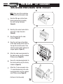
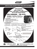
DASH DISASSEMBLY
TOYOTA CAMRY/CAMRY HYBRID 2007-2011
Disconnect the negative battery terminal
to prevent an accidental short circuit.
Turn the shift knob counterclockwise to
remove.
1
2
Unclip and remove (1) trim panel from each
side of the pocket below the radio/climate
control assembly. (2 panels total)
(Figure A)
3
Unclip and remove the top of the center
console inc
luding the cup holders.
(Figure B)
5
1
2
3
4
5
6
A
1
2
3
4
5
6
B
1
2
3
4
5
6
C
Continued on Page 2.
Unclip and remove the shift knob trim
panel. (Figure B)
4
Remove (1) Phillips screw from each
side of pocket below the radio/climate
control assembly (2 screws total).
(Figure C)
6
Unclip and remove the pocket.
(Figure C)
7

2
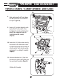
99-8218
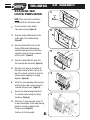
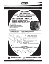
DASH DISASSEMBLY
8
9
10
Remove the (10) Phillips screws securing
the brackets to the radio/c
limate control
assembly and separate the radio from the
climate controls. (Retain climate controls
and screws for use during kit assembly).
(Figure C)
1
2
3
4
5
6
A
1
2
3
4
5
6
B
C
Unclip and remove the A/C vents above
the radio. (Take care not to scratch the
dash panel. (Figure A)
11
Remove (2) 10mm bolts above the radio
(behind the A/C vents) and (2) 10mm
bolts below the climate controls (behind
pocket) then unplug and remove the
radio/climate control assembly.
(Figure B)
Unscrew and remove the (2) Clips from
the back of the factory radio. (Retain clips
for use during kit assembly. (Figure C)
Continue to kit assemby.
TOYOTA CAMRY / CAMRY HYBRID 2007-2011

3
99-8218
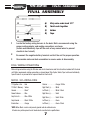
KIT ASSEMBLY
DIN RADIO PROVISION WITH POCKET
B
C
A
1
Slide the DIN cage into the Radio
Housing and secure by bending
the metal locking tabs down.
(
Figure A)
2
Slide the after-market radio into the
cage until it snaps into place.
(
Figure B)
3
Snap the pocket into the radio
housing. (
Figure B)
NOTE: Refer also to the instructions
included with the aftermarket radio.
Continue to Final Assembly.
4
Align the small legs on the bottom
of the radio housing with the slots in
the top of the climate control. Then
slide the c
limate control sideways to
engage together. (
Figure C)
5
Attach the radio housing brackets to
the radio housing using the included
Phillips screws. (
Figure D)
D
6
Secure the radio housing brackets to
the climate control using the factory
hardware.
(
Figure D)
7
Attach the (2) clips removed in step
11 in dash disassembly to the radio
housing brackets using the supplied
small Phillips screws.(
Figure D)

99-8218
KIT ASSEMBLY
4
B
C
A
1
Mount the ISO Brackets to the
radio with the screws supplied
with the radio. (
Figure A)
2
Slide the radio into the radio open-
ing until the side clips engage.
(
Figure B)
4
Snap the pocket into the radio
housing. (
Figure B)
NOTE: Refer also to the instructions
included with the aftermarket radio.
Continue to Final Assembly.
5
Align the small legs on the bottom
of the radio housing with the slots in
the top of the climate control. Then
slide the climate control sideways to
engage together.
(
Figure C)
6
Attach the radio housing brackets to
the radio housing using the included
Phillips screws. (
Figure D)
D
7
Secure the radio housing brackets to
the climate control using the factory
hardware.
(
Figure D)
8
Attach the (2) clips removed in step
11 in dash disassembly to the radio
housing brackets using the supplied
small Phillips screws.(
Figure D)
ISO RADIO PROVISION WITH POCKET
3
Snap the Trim plate into the Radio
Housing. (
Figure B)

99-8218
KIT ASSEMBLY
5
B
C
A
1
Cut and remove center divider
from radio housing. (
Figure A)
2
Snap the Double DIN brackets to the
inside edge of the radio housing.
(
Figure B)
3
Slide the Double DIN radio into the
Double DIN bracket/radio housing
assembly and secure the radio to the
assembly using the screws supplied
with the radio. (
Figure C)
NOTE: Refer also to the instructions
included with the aftermarket radio.
Continue to Final Assembly.
4
Snap the Double DIN trim-plate into
the housing/radio assembly. (
Figure C)
5
Align the small legs on the bottom of
the radio housing with the slots in the
top of the climate control then slide the
clima
te control sideways to engage
together. (
Figure D)
D
6
Attach the corresponding radio housing
bracket to the radio housing using the
included Phillips screws. (
Figure E)
8
Attach the (2) clips removed in step 11 in
dash disassembly to the radio housing
brackets using the supplied small Phillips
screws.(
Figure E)
DOUBLE DIN
7
Secure the radio housing brackets to
the climate control using the factory
hardware.
(
Figure E)
RADIO PROVISION
E

99-8218
KIT ASSEMBLY
6
B
C
A
1
Cut and remove center divider
from radio housing. (
Figure A)
2
Snap the Double DIN brackets to the
inside edge of the radio housing.
(
Figure B)
3
Slide the Stacked ISO units into the
Double DIN bracket/radio housing
assembly and secure the radio to the
assembly using the screws supplied
with the units. (
Figure C)
NOTE: Refer also to the instructions
included with the aftermarket radio.
Continue to Final Assembly.
4
Snap the Double DIN trim-plate into
the housing/radio assembly. (
Figure C)
5
Align the small legs on the bottom of
the radio housing with the slots in the
top of the climate control then slide the
clima
te control sideways to engage
together. (
Figure D)
D
6
Attach the corresponding radio housing
bracket to the radio housing using the
included Phillips screws. (
Figure E)
8
Attach the (2) clips removed in step 11
in dash disassembly to the radio housing
brackets using the supplied small
Phillips screws.(
Figure E)
STACKED ISO
7
Secure the radio housing brackets to
the climate control using the factory
hardware.
(
Figure E)
UNITS PROVISION
E

7
99-8218
FINAL ASSEMBLY
FINAL ASSEMBLY
1
Locate the factory wiring harness in the dash. Metra recommends using the
proper mating adapter and making connections as shown.
(Isolate and individually tape off the ends of any unused wires to prevent
electrical short circuit.)
2
Re-connect the negative battery terminal and test the unit for proper operation.
3
Reassemble radio and dash assemblies in reverse order of disassembly.
A
A) Strip wire ends back 1/2"
B) Twist ends together
C) Solder
D)
Tape
B
C
D
Make wiring connections using the EIA color code chart shown below and the instructions included with the head
unit. Metra recommends making connections as shown below; Strip, Splice, Solder, Tape. Isolate and individually
tape off ends of any unused wires to prevent electrical short circuit.
12V Ignition / Acc . . . Red
12V Batt / Memory . . Yellow
Ground . . . . . . . . . . . Black*
Power Antenna . . . . . Blue
Amp Turn-On . . . . . . Blue / White
Amp Ground . . . . . . . Black / White
Illumination. . . . . . . . Orange
Dimmer . . . . . . . . . . Orange / White
Right Front (+) . . . . . White
Left Front (-) . . . . . . . White / Black
Right Rear (+). . . . . . Violet
Right Rear (-) . . . . . . Violet / Black
Left Rear (+). . . . . . . Green
Left Rear (-) . . . . . . . Green / Black
*NOTE: When Black a wire is not present, ground radio to vehicle chassis.
All colors may not be present on all leads due to manufacturer’s specifications.
METRA / EIA WIRING CODE
FINAL WIRING CONNECTIONS

8
99-8218
NOTES

9
99-8218
NOTES

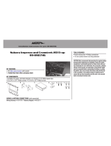
99-8218 INSTRUCTIONS
1-800-221-0932 www.metraonline.com
REV. 07-22-10 © COPYRIGHT 2004-2010 METRA ELECTRONICS CORPORATION INST99-8218
-
 1
1
-
 2
2
-
 3
3
-
 4
4
-
 5
5
-
 6
6
-
 7
7
-
 8
8
-
 9
9
-
 10
10
-
 11
11
-
 12
12


Metra Electronics 99-8218 User manual
- Category
- Motor vehicle electronics
- Type
- User manual
Ask a question and I''ll find the answer in the document
Finding information in a document is now easier with AI
Related papers
-
 Metra Electronics 99-8907HG Installation Instructions Manual
-
 Metra Electronics ACURA 95-7868B User manual
-
 Metra Electronics 99-8225G User manual
-
 Metra Electronics 99-7878B User manual
-
Metra 88-00-2020 User manual
-
-
 Metra Electronics 99-5822B User manual
-
 Metra Electronics 95-5822B User manual
-
 Metra Electronics 99-8227S User manual
-
 Metra Electronics 95-8210 User manual


Other documents
-
Metra 99-2007 Specification
-
-
-
PAC BKTOYK962 User manual
-
Metra 99-7876 Installation guide
-
-
-
-
Toyota 95-8211 User manual
-
Dodge 99-6512 Installation guide