Williams Sound WIR SYS 2 User manual
- Category
- Musical Equipment
- Type
- User manual
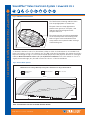
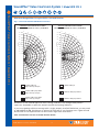
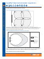
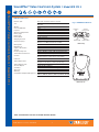
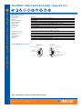
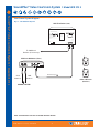
Williams Sound WIR SYS 2 courtroom assistive listening system is designed for spaces with limited budgets. It contains a TX9 emitter and a MOD 232 modulator that can be either rack-mounted or wall-mounted. The system includes three headset RX14-2 receivers for use with headphones. The RX22-4 receiver can be used with a neckloop to amplify the participant’s telecoil equipped hearing aid. The system uses infrared technology to ensure privacy and security, and it meets and exceeds government ADA regulations for public hearing assistance.
Williams Sound WIR SYS 2 courtroom assistive listening system is designed for spaces with limited budgets. It contains a TX9 emitter and a MOD 232 modulator that can be either rack-mounted or wall-mounted. The system includes three headset RX14-2 receivers for use with headphones. The RX22-4 receiver can be used with a neckloop to amplify the participant’s telecoil equipped hearing aid. The system uses infrared technology to ensure privacy and security, and it meets and exceeds government ADA regulations for public hearing assistance.


-
 1
1
-
 2
2
-
 3
3
-
 4
4
-
 5
5
-
 6
6
-
 7
7
-
 8
8
-
 9
9
-
 10
10
-
 11
11
-
 12
12


Williams Sound WIR SYS 2 User manual
- Category
- Musical Equipment
- Type
- User manual
Williams Sound WIR SYS 2 courtroom assistive listening system is designed for spaces with limited budgets. It contains a TX9 emitter and a MOD 232 modulator that can be either rack-mounted or wall-mounted. The system includes three headset RX14-2 receivers for use with headphones. The RX22-4 receiver can be used with a neckloop to amplify the participant’s telecoil equipped hearing aid. The system uses infrared technology to ensure privacy and security, and it meets and exceeds government ADA regulations for public hearing assistance.
Ask a question and I''ll find the answer in the document
Finding information in a document is now easier with AI
Related papers
-
Williams Sound SoundPlus Basic Courtroom System WIR SYS 1 User manual
-
-
-
WILLIAMSSOUND IR SY21 D User manual
-
-
-
-
Williams Sound SoundPlus Infrared Transmitter WIR TX90 User manual
-
-
Other documents
-
Power Acoustik HP-10S Owner's manual
-
 T'nB CSAFASPH36471 Datasheet
-
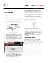 Williams AV WilliamsAV IR+ Modulator User manual
-
Sony MDRRF850RK Datasheet
-
Ematic FM Hi-Fi wireless Operating instructions
-
Sharkoon 4044951010967 Datasheet
-
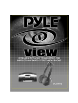 PYLE Audio VIEW PLVWH2 User manual
-
PyleHome PHPW5 Owner's manual
-
Barco OverView cDG67-DL Owner's manual
-
Quatech 2.4GHz User manual


