Williams Sound SoundPlus Infrared Transmitter WIR TX90 User manual

Category
Musical Equipment
Type
User manual

This manual is also suitable for

SoundPlus
®
Infrared Transmitter • Model WIR TX90
SoundPlus
®
Infrared Transmitter • Model WIR TX90
D
D
Description:
The TX90 two channel IR transmitter combines modulator and emitter technology into a single operating unit, which
reduces operating cost and eliminates precious rack space. The TX90 transmitter produces a wide-angle infrared sig-
nal that concentrates the IR energy efficiently in the listening area. Operating on the 2.3-3.8 MHz bandwidth, the
TX90 is less susceptible to radio and lighting interference. Each TX90 transmitter can cover up to 28,000 sq ft (2,600
sq m) in single-channel operation. The coverage area can be easily increased by connecting additional TX9 emitters.
A wall/ceiling omnidirectional mount is included, and stand kits are available for portable operation.
Dimensions, Weight: 11.25" W x 6.25" H x 2.125" D (28.6 cm x 15.9 cm x 5.4 cm), 1.8 lbs (0.8 kg)
Color: Black with white legends, black acrylic lens
Power Supply: Wall Transformer, 24 VAC, 50-60 Hz, 35 VA, 3-pin MOLEX Connector
North America: TFP 010, UL/CSA
Europe: TFP 027-01, 2-pin Schuko plug, CE
UK: TFP 027-02, 3-pin UK plug, CE
Power Cable: NEC Class 2 wiring, two-conductor, 18 ga., 200’ (61m) max. length
Modulation: FM Wideband, +50kHz deviation max., 50uS pre-emphasis
Carrier Frequency: Channel A: Selectable, 2.3/2.8 MHz,
Channel B: Selectable, 3.3/3.8 MHz
Emitter IR Power: 3.5 watts
Coverage Area: 28,000 ft
2
(2,600 m
2
) in single-channel mode when using the RX22-4 Receiver
18,000 ft
2
(1,670 m
2
) in four-channel mode when using the RX22-4 Receiver
3,500 ft
2
(325 m
2
) in single-channel mode when using the RX14-2 Receiver
3,063 ft
2
(285 m
2
) in single-channel mode when using the RX16 Receiver
(See coverage area diagrams)
Signal-to-Noise Ratio: >75 dB, +3dB
Frequency Response: 80 to 15,000 Hz, electrical response
Total Harmonic Distortion: Less than .2%, electrical response at 1kHz
Compression: Music preset 1:1, Voice preset 1.5:1, Hearing Assist preset 2:1
Auto Carrier Shut-Off: 20 minute timer shuts off carrier when no audio is present
WIR TX90 Transmitter:
Power Indicator: Red LED
Audio Volume Level Controls: CHA and CHB Input Level, press to select, 28 dB adjustable range
Audio Indicators: CHA and CHB Audio Level, yellow LED, flash
Carrier LEDs: 2 green LED carrier “on” indicators
Phones Output: 3.5mm TRS headphone jack. CH A tip, CH B ring on jack, 32 ohm headphone (min)
Application Preset: Music, Voice, Hearing Assist. Frequency response; Music: Flat; Voice: Mid-range
boost; Hearing Assist: High frequency boost
Tone Control: Press to select, 21 dB adjustable range (1 kHz between low boost/hi-cut and low
cut/hi boost).
©2008, Williams Sound Corp. MCAT 042C
1
Applications:
Cinemas • Simultaneous Interpretation • Audio Description • Conferences • Multi-Media Rooms
Boardrooms • Courtrooms • Schools • Universities • Churches
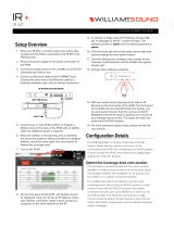
Fig. 1: TX90 Bottom View:
NOTE: SPECIFICATIONS SUBJECT TO CHANGE WITHOUT NOTICE!
* 90 days on accessories.
SoundPlus
®
Infrared Transmitter • Model WIR TX90
SoundPlus
®
Infrared Transmitter • Model WIR TX90
D
D
NOTE: SPECIFICATIONS SUBJECT TO CHANGE WITHOUT NOTICE!
Fig 2: TX90 Rear View
Power Input: 3-Pin Molex, 24 VAC, 50-60 Hz, 35 VA
Audio Input Connector: CHA and CHB, 3 wire Phoenix
Input Level: Balanced or unbalanced, 316 mVRMS (-10dBV) nominal, 5.7k input impedance; max
input (over volume range)
-21 to +7 dBV.
Baseband Output: BNC, 50 Ω, for use with TX9 only
Baseband Cable: RG 58 Coax, BNC connectors, maximum 1000’ (300m) length
Operating Requirements: 0-50º C (+32°F to 122°F) ambient temperature, non-condensing, non-corrosive atmosphere
Mounting Kits: Wall or Ceiling Mount: BKT 024 Omnidirectional mount;
Optional: Tripod Stands: SS-11 or SS-6
Warranty: 5 years on transmitter, 90 days on accessories
Approvals: CE, FCC, RoHS, WEEE
Compatible Receivers: WIR RX22-4 Four-Channel Receiver, WIR RX14-2 Two-Channel Receiver,
WIR RX16 Two-Channel Receiver
Notes: Specifications: Single end input, volume & tone controls at mid point, 1 kHz,
“Music” Preset
©2008, Williams Sound Corp. MCAT 042C
2
SoundPlus
®
Infrared Transmitter • Model WIR TX90
SoundPlus
®
Infrared Transmitter • Model WIR TX90
D
D
NOTE: SPECIFICATIONS SUBJECT TO CHANGE WITHOUT NOTICE!
90
Feet
Feet
90 100 110 120 130 140 150 160
80
80
70
70
60
60
50
50
40
40
30
30
20
20
10
10
0
0
-10
-20
-30
-40
-50
-60
-70
-80
-90
RX22-4 Receiver
Receiver Coverage Area with TX90
Transmitter in Single Channel Mode
RX16 Receiver
RX14-2 Receiver
Fig. 3: Receiver Coverage Area with TX90 Transmitter in Single Channel Mode
The coverage area for the TX90 will vary depending on the receiver being used. The diagram
above demonstrates the receiver coverage when operating a single TX90 transmitter in single chan-
nel mode. Patterns are direct radiation patterns.
Note: Reflections of the infrared light from walls, ceilings and floors may change these patterns.
RX22-4
RX14-2
RX16
©2008, Williams Sound Corp. MCAT 042C
3
SoundPlus
®
Infrared Transmitter • Model WIR TX90
SoundPlus
®
Infrared Transmitter • Model WIR TX90
D
D
NOTE: SPECIFICATIONS SUBJECT TO CHANGE WITHOUT NOTICE!
The TX90 floods the listening audience with a
cone shape light pattern as shown here.
The path of the cone shape light leaves a
pattern on the ground, or "foot print, " and
indicates where the strongest receiver
reception will occur.
The actual coverage area will vary depending
on the sensitivity of the receiver being used.
Refer to Figures 3 and 6 to determine how
many emitters are required for 100% coverage
of the listening area.
Minimum Receiver Range When Operating with a TX90 Transmitter in Single Channel Mode
RX22-4 Receiver:
150' (45 m)
RX14-2: 80' (24 m) RX16: 70' (21 m)
SCREEN
30'
STAGE
6'
Center Of Emitter Beam
TX90
(Range)
To determine the best location for the transmitter, it helps to think of the IR transmitter as an invisible
floodlight. You’ll want to aim it so the listeners are “flooded” with the infrared light. The transmitter
should also be positioned high enough so it won’t be blocked by people and other physical obstructions.
See Figure 5 below. Mount the transmitter at least 2 ft. (.61 m) above the audience. Position the transmitter
to face in a slightly downward angle, 20°, that will increase the “throw” of the infrared beam.
Fig. 4: 3-Dimension Foot Pattern
Fig. 5: Vertical Beam Spread
©2008, Williams Sound Corp. MCAT 042C
4
SoundPlus
®
Infrared Transmitter • Model WIR TX90
SoundPlus
®
Infrared Transmitter • Model WIR TX90
D
D
NOTE: SPECIFICATIONS SUBJECT TO CHANGE WITHOUT NOTICE!
Maximum Range When Using the RX22-4 Infrared Receiver
20
6
12
18
24
30
36
42
48
54
60
40
60
80
100
120
140
160
180
200
FEET
METERS
– 90
– 80
– 70
– 60
– 50
– 40
– 30
– 20
– 10
0
10
20
30
40
50
60
70
80
90
1 Channel, 1 nW/sq cm
(Approx. 28000 sq ft, 2600 sq m)
2 Channel, 1 nW/sq cm per channel
(Approx. 18000 sq ft, 1700 sq m)
4 Channel, 1 nW/sq cm per channel
(Approx. 11000 sq ft, 1000 sq m)
1 Channel, 1 nW/sq cm
2 Channels, 1 nW/sq cm per channel
4 Channels, 1 nW/sq cm per channel
HORIZONTAL RADIATION POLAR PATTERNS
DISTANCE FROM EMITTER TO 1 nW/sq cm CONTOUR
VERTICAL RADIATION POLAR PATTERNS
DISTANCE FROM EMITTER TO 1 nW/sq cm CONTOUR
20
6
12
18
24
30
36
42
48
54
60
40
60
80
100
120
140
160
180
200
FEET
METERS
– 90
– 80
– 70
– 60
– 50
– 40
– 30
– 20
– 10
0
10
20
30
40
50
60
70
80
90
Reflections of the infrared light from walls, ceilings, and floors may change these patterns.
Important: Remember to point the emitter towards the listening audience!
If you’re not getting sufficient coverage with a single, properly installed TX90 Transmitter, you may need
to add additional WIR TX90 Transmitters to achieve full coverage of your listening area. Figures 7a and
7b illustrate how multiple emitters can be used for large room installations.
Fig. 6: Horizontal and Vertical Radiation Polar Plots
©2008, Williams Sound Corp. MCAT 042C
5
SoundPlus
®
Infrared Transmitter • Model WIR TX90
SoundPlus
®
Infrared Transmitter • Model WIR TX90
D
D
NOTE: SPECIFICATIONS SUBJECT TO CHANGE WITHOUT NOTICE!
TX9 TX9
TX9 TX9
TX90
Coverage Area
with Single
Transmitter
Coverage Area
with Second Emitter
Added to Same
Emission Point
(50% increase)
TX9
Fig. 7a: Overlapping Illumination Patterns to Cover Larger Listening Areas
Multiple Emitters Installed to Maximize Coverage
Fig. 7b: Overlapping Illumination Patterns to Cover Larger Listening Areas
Fig. 7a above is a typical example of how multiple emitters are used to cover larger listening areas.
Generally it is desirable for the illumination patterns to overlap. Note: The coverage area will vary depend-
ing on the infrared receiver being used; refer to Figures 3 and 6 to determine how many emitters are
required to achieve full coverage of a listening area.
When a TX90 transmitter and TX9 emitter are used at the same emission point in single channel mode, the
overall coverage area increases 50%. When using an RX22-4 receiver, as a result, the coverage area will
increase to an estimated 42,000 ft
2
(3,902 m
2
); the RX14-2 will increase to 5,250 ft
2
(488 m
2
); the RX16 will
increase to 4,590 ft
2
(426 m
2
).
©2008, Williams Sound Corp. MCAT 042C
6
SoundPlus
®
Infrared Transmitter • Model WIR TX90
SoundPlus
®
Infrared Transmitter • Model WIR TX90
D
D
NOTE: SPECIFICATIONS SUBJECT TO CHANGE WITHOUT NOTICE!
Receiver Style: Body-Pack, dual-lens detector, lanyard
Size: 4.5" L x 2.85" W x 1.2" H (114.3 mm x 72.4 mm x
30.4 mm)
Weight: 4.6 oz (130 g) with batteries
Color and Material: Black
Lanyard: 3 ft (.91 m), allows receiver to be worn around the neck
Operating Temperature: -10° C to +50° C
Battery Type: 2 x AA, alkaline (BAT 001) or NiMH (BAT 026)
Battery Life: Alkaline: 60 hours, NiMH: 30 hours/charge
Battery Drain: 25 mA, nominal
Charging Contacts: For use only with CHG 3512
Carrier Frequency: Channel 1: 2.3 MHz, Channel 2: 2.8 MHz
Channel 3: 3.3 MHz, Channel 4: 3.8 MHz
De-Emphasis: 50 uS
FM Deviation: ±50 kHz
Signal-to-Noise Ratio: 60dB min.
Squelch: Receiver squelches (mutes) at 40 dB S/N ratio
Frequency Response: 25 Hz to 16 KHz, +1 dB, -3 dB, electrical response
Total Harmonic Distortion: Less than 1%, electrical response
Controls: ON/OFF/VOLUME: combination thumbwheel knob
Channel Selector: four-position rotary switch
Indicators: Red LED “ON” indicator, flashes to indicate Low battery
Audio Output Jacks: 3.5 mm stereo mini phone jack
Accepts 3.5 mm mono or stereo phone plug
Audio Output Power: 15 mW max at 32 Ω
Acoustic Output: 110 dB SSPL90 w/ EAR 013
Sensitivity: Better than 1 nW/cm
2
for 40 dB signal-to-noise ratio
Approvals: CE, FCC, RoHS, WEEE
Warranty: 5 years on receiver, 90 days on accessories
Compatible Headphones/Earphones: Mono or stereo, 8-32 ohms, 3.5 mm mini phone plug,
HED 021, HED 026, EAR 013, EAR 014, EAR 022, NKL 001
RX22-4 Front
RX22-4 Top
On/Off
Volume Switch
Earphone
Jack
"On"
Indicator LED
Channel
Selector Knob
OFF
Optional WIR RX22-4 Receiver:
©2008, Williams Sound Corp. MCAT 042C
7
Fig. 8: WIR RX22-4 Receiver
SoundPlus
®
Infrared Transmitter • Model WIR TX90
SoundPlus
®
Infrared Transmitter • Model WIR TX90
D
D
NOTE: SPECIFICATIONS SUBJECT TO CHANGE WITHOUT NOTICE!
Optional WIR RX14-2 Receiver
©2008, Williams Sound Corp. MCAT 042C
8
Receiver Style: Headset
Earpad Size: 2.5" (6.5 cm) diameter, adjustable headband
Weight: 6.7 oz (191 g) without batteries
Color and Material: Black, plastic
Operating Range: Up to 3,500 ft
2
(325 m
2
) when using a single WIR TX90 Transmitter
Battery Type: AAA Alkaline batteries (BAT 010)
Battery Life: Alkaline: 50 hours
Battery Drain: 25 mA, nominal
Controls: ON/OFF switch
(2) Thumbwheel volume control knob, left and right
(1) Frequency push-button selector, 2.3 MHz or 2.8 MHz
Acoustic Output: 118 dB MAX SSPL90, +/- dB with 6 cc coupler
Warranty: 1-year warranty (excludes physical damage)
Approvals: CE, RoHS
|
|
|
|
|
|
|
|
|
|
|
OFF
ON
Volume
On/Off
Infrared "Eye"
AAA
Battery
Compartment
+–
Right Earphone
|
|
|
|
|
|
|
|
|
|
|
Frequency
Selector: 2.3 MHz
or 2.8 MHz
Infrared "Eye"
Volume
Left Earphone
+–
AAA
Battery
Compartment
Fig 9: WIR RX14-2 Side View
SoundPlus
®
Infrared Transmitter • Model WIR TX90
SoundPlus
®
Infrared Transmitter • Model WIR TX90
D
D
NOTE: SPECIFICATIONS SUBJECT TO CHANGE WITHOUT NOTICE!
Bid Specs
WIR TX90 Transmitter
The Williams Sound Corp. WIR TX90 transmitter shall consist of an all-in-one modulator and emitter operating on
switchable carrier frequencies of 2.3/2.8 MHz or 3.3/3.8 MHz. The carrier frequency shall use 50 kHz deviation and
50µs pre-emphasis.
The transmitter shall have a range of 28,000 ft
2
(2,600 m
2
) in single channel mode when using the RX22-4 receiver.
The transmitter shall be contained in a metal housing with a durable plastic lens. The transmitter shall be convec-
tion cooled without fans. The transmitter shall include an omni-directional mounting bracket for permanent instal-
lations. Additional brackets shall be available for different mounting options.
The transmitter shall provide two channels of selectable carrier frequencies: CH A 2.3/2.8 MHz or CH B 3.3/3.8 MHz.
Two transmitters used in tandem shall provide up 4 simultaneous channels.
The transmitter shall have two Phoenix connectors on the back for balanced or unbalanced line input. All controls
and indicators shall be accessible on the bottom of the panel of the transmitter.
The transmitter shall have three application presets: Music, Hearing Assistance and Voice accessible by thumbscrew
adjuster.
There shall be a 3.5mm stereo headphone jack for monitoring the processed audio before being transmitted.
Two BNC (50Ω) baseband output jacks shall be provided on the back panel for more coverage needs. The TX9 emit-
ter panels must be used with the TX90 transmitter via RG58 coax cable.
The transmitter shall be powered by an external 24VAC, 50-60 Hz, 35VA power supply. The power connector shall
be a three pin Molex type. Additional emitters shall require individual external power supplies.
The transmitter shall be covered by a five-year warranty on parts and labor. The transmitter shall be the Williams
Sound Corp. model WIR TX90
©2008, Williams Sound Corp. MCAT 042C
9
SoundPlus
®
Infrared Transmitter • Model WIR TX90
SoundPlus
®
Infrared Transmitter • Model WIR TX90
D
D
NOTE: SPECIFICATIONS SUBJECT TO CHANGE WITHOUT NOTICE!
United States
Williams Sound Corp.
10321 W. 70th Street
Eden Prairie, MN 55344
Phone: 800-328-6190 or 952-943-2252
Fax: 952-943-2174
Web: www.williamssound.com
Canada
Thorvin Electronics
2861 Sherwood Heights Dr. Units 36-37
Oakville, ON L6J-7K1 Canada
Phone: 800-323-6634 or 905-829-3040
Fax: 905-829-4196
Web: www.thorvinelectronics.com
United Kingdom
Sound Associates
Keeble House, 81 Island Farm Road
West Molesey, Surrey KT 2SA
United Kingdom
Phone: (44) 020 8939 5900
Fax: (44) 020 8939 5901
Web: www.soundassociates.co.uk
Asia, Australia, Europe, Latin America, South America, South Africa
International Sales Department
Williams Sound Corp.
10321 W. 70th Street
Eden Prairie, MN 55344 USA
Phone: +1 952 224 7791
Fax: +1 952 943 2174
Web: www.williamssound.com
Contact:
©2008, Williams Sound Corp. MCAT 042C
10
  • Page 1 1
  • Page 2 2
  • Page 3 3
  • Page 4 4
  • Page 5 5
  • Page 6 6
  • Page 7 7
  • Page 8 8
  • Page 9 9
  • Page 10 10

Williams Sound SoundPlus Infrared Transmitter WIR TX90 User manual

Category
Musical Equipment
Type
User manual
This manual is also suitable for

Ask a question and I''ll find the answer in the document

Finding information in a document is now easier with AI