Page is loading ...

Save ThisManual
For Future Reference
owner's
manual
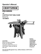
MODEL NO.
113.197411
10-1NCH ELECTRONIC
RADIAL SAW WITH
4_,-INCH CABINET
AND 2 DOORS
or
113.197511
10-1NCH ELECTRONIC
RADIAL SAW
WITH 44-1NCH CABINET
AND 2 DOORS AND
CASTERS
or
113.197611
10-1NCH ELECTRONIC
RADIAL SAW WITH
44-1NCH CABINET
AND 6 DRAWERS
Serial
Number
Model :]nd serial numbers
may be found on the left
hand side of the base.
You shculd record both
model and serial number in
a safe place for future use.
FORYOUR
SAFETY:
READ ALL
INSTRUCTIONS
CAREFULLY
r
I
113.19761
113.197411
SEARS / r.RRFT$IViRN
10-1NCH RADIALSAW
• assembly
• operating
• repair parts
\ Y\
Sold by SEARS, ROEBUCK AND CO., Chicago, IL60684 U.S.A.
Part No. SP5539 Printed in U.S.A,

Table of Contents
Section Title .......................... Page
Safety ......................................... 3
Assembly ...................................... 10
Controls ....................................... 34
Alignment and Adjustment ............................ 37
Digital Display ................................... 48
Electrical Connections ............................... 54
Crosscutting ..................................... 57
Ripping ....................................... 61
Cutting Aides .................................... 69
Accessories ..................................... 72
Maintenance .................................... 75
Troubleshooting .................................. 79
Repair Parts ..................................... 84
Index ......................................... 103
FULL ONE YEAR WARRANTY ON CRAFTSMAN RADIAL ARM SAW
If within one year from the date of purchase, this Craftsman Radial Saw fails due
to a defect in material or workmanship, Sears will repair it, free of charge.
WARRANTY SERVICE IS AVAILABLE BY SIMPLY CONTACTING THE
NEAREST SEARS SERVICE CENTER/DEPARTMENT THROUGHOUT THE
UNITED STATES.
This warranty applies only while this product is used in the United States.
This warranty gives you specific legal rights and you may also have other rights
v,hich vary from state to state.
SEARS, ROEBUCK AND CO. DEPT. 698/731A SEARS TOWER,
CHICAGO, IL 60684

Safety
This manual has safety information and in-
structions to help users eliminate or
reduce the risk of accidents and injuries,
including:
1. Severe cuts, and loss of fingers or other
body parts due to contact with the blade
2. Eye impact injuries, and blindness, from
being hit by a thrown workpiece,
workpiece chips or pieces of blade
3. Bodily impact injuries, broken bones,
and internal organ damage from being hit
by a thrown work'piece
4. Shock or electrocution
5. Burns.
Safety Symbol and Signal Words
An exclamation mark inside a triangle is
the safety alert symbol.
It is used to draw attention to safety infor-
mation in the manual and on the saw. It is
followed by a signal word, DANGER,
WARNING, or CAUTION, which tells
the level of risk:
_h, DANGER: means if the safety infor-
mation is not followed someone will be
seriously injured or killed.
WARNING: mearks if the safety infor-
mation is not followed someone could be
seriously injured or killed.
_ CAUTION: means if the safety infor-
mation is not followed someone might be
injured.
Read and follow all safety information
and instructions.
Major Hazards
Three major hazards are associated with
using the radial arm saw for ripping. They
are outfeed zone hazard, kickback, and
wrong way feed.
This section only briefly explains these
hazards. Read the ripping and crosscut-
ting safety sections for more detailed ex-
planations of these and other hazards.
Outfeed Zone Hazard
_DANGER
If you reach around the blade to the out-
feed side when ripping, and try to hold
down or pull the workpiece through to
complete a cut, the rotational force of the
blade will pull your hand back into the
blade.
Fingers will be cut off.
Read and follow the information and in-
structions under ripping safety.

Safety
Kickback Hazard
Kickback is the uncontrolled propelling of
the workpiece back toward the user
during ripping.
The cause of kickback is the binding or
pinching of the blade in the workpiece.
Several conditions can cause the blade to
bind or pinch.
When a workpiece kicks back, it could hit
hard enough to cause internal organ in-
juu, broken bones, or death.
Read and follow the information and in-
structions under ripping safety.
WARNING
KICKBACKItI_
Wrong Way Feed Hazard
Wrong way feed is ripping by feeding the
workpiece into the outfeed side of the
blade.
The rotational force of the blade can grab
and pull the workpiece.
Before you can let go or pull back, the
force could pull your hand along with the
workpiece into the blade. Fingers or hand
could be cut off.
The propelled workpiece could hit a by-
stander, causing severe impact injury or
death.
Read and follow the information and in-
structions under ripping safety.
kWARNING
Wrong Way Feed

Safety Instructions
Read and follow all safety instructions.
Personal Safety Instructions
1. Wear safety goggles labeled "ANSI
Z87.1" on the package. It means the gog-
gles meet impact standards set by the
American National Standards Institute.
Regular eyeglasses are not safety goggles.
2. Wear close fitting clothes, short
sleeved shirts, and non-slip shoes. Tie up
long hair. Do not wear gloves, ties, jewel-
ry, loose clothing, or long sleeves. These
can get caught in the spinning blade and
pull body parts into the blade.
3. Wear dust mask to keep from inhaling
fine particles.
4. Wear ear protectors, plugs or muffs if
you use saw daily.
5. Keep good footing and balance; do not
over-reach.
Work Area Safety Instructions
1. Keep children, pets, and visitors out of
work area; they could be hit by a thrown
workpiece, workpiece chips or pieces of
blade.
2. Turn saw off, remove yellow key, and
unplug before leaving work area. Do not
leave until blade has stopped spinning.
3. Make work area child-proof: remove
yellow key to prevent accidental start-up;
store key out of sight and reach; lock
work area.
4. Keep floors clean and free of sawdust,
wax and other slippery materials.
5. Keep work area well lighted and un-
cluttered.
6. Use saw only in dry area. Do not use in
wet or damp areas.
Safety Goggles
Dust Mask
Ear Protectors
Safety

Safety
Saw Safety Instructions
1. Use guard, pawls and spreader accord-
ing to instructions. Keep them in working
order.
2. Routinely check saw for broken or
damaged parts. Repair or replace
damaged parts before using saw. Check
new or repaired parts for alignment, bind-
ing, and correct installation.
3. Unplug saw before doing maintenance,
making adjustments, correcting align-
ment, or changing blades.
4. Do not force saw. Use saw, blades and
accessories only as intended.
5. tlave yellow key out and saw switched
off before plugging in power cord.
6. Before turning on saw, clear table of all
objects except workpiece to be cut and
necessary fixtures, clamps, or feather-
boards.
7. If blade jams, turn saw off immediately,
remove yellow key, then free blade. Do
not try to free blade with saw on.
8. Turn saw off if it vibrates too much or
makes an odd sound. Correct any prob-
lena before restarting saw.
9. Do not layout, assemble, or setup work
with saw on, or while blade is spinning.
10. Keep saw table clean.
11. Store items away from saw. Do not
climb on saw or stand on saw table to
reach items because saw can tip over.
Workpiece Safety Instructions
1. Cut only wood, woodlike or plastic
materials. Do not cut metal.
2. Cut only one workpiece at a time.
Stacking or placing workpieces edge to
edge can cause user to lose control of
workpiece.

Safety
3. Rip only workpieces longer than the
diameter of the blade. Do not rip
workpieces that are shorter than the
diameter of the blade being used.
4. Workpieces that extend beyond the
saw table can shift, twist, rise up from the
table, or fall as they are cut. Support
workpiece with table extensions the same
height as the saw table.
5. To prevent tipping, support outer ends
of extensions with sturdy legs or an outrig-
ger.
6. Do not use another person to help sup-
port workpieces or to aid by pushing or
pulling on workpieces, because these ac-
tions can cause kickback. Use table exten-
sions.
7. Use clamps or vice to hold workpiece.
It's safer than using your hands.
Blade Safety Instructions
I. Use only blades marked for at least
3450 rpm.
2. Use only 10" or smaller diameter
blades.
3. Use blades for their recommended cut-
ting procedures.
4. Keep blade sharp and clean.
5. Do not overtighten blade nut because
blade collar could warp.
6. Do not turn saw on and off in rapid se-
quence because blade can loosen.
7. Blade should stop within 15 seconds
after saw is switched off. If blade takes
longer, the saw needs repair. Contact
Sears Service Center.

Safety
On-Product Safety Labels
There are several safety labels on the saw.
They alert the user to hazards explained in
the manual and remind the user how to
avoid the hazard.
Note where they are located on the saw.
Read and follow the safety information
and instructions in these labels. Refer to
the manual for detailed explanations and
instructions.
On the outfeed side of the guard is this
safety label to alert you to wrong way feed:
ADANGERi
On the infeed side of the guard is this
safety label to alert you to kickback, and
to remind you to lower the guard nose
(hold down) for ripping:
kWARNING
KICKBACKI!II_

Safety
On the side surface of the motor, visible
from the infeed side when the saw is in a
rip position, is this safety label to alert you
to outfeed zone hazard:
DANGER
Near the saw handle is this safety label to
alert you to thrown objects and to remind
you to wear safety goggles:
, WARNING
On the bottom surface of the motor,
visible when the cutting tool is horizontal,
is this safety label to alert you use a guard
when edge molding, and to position cut-
ting tool behind fence: (see Accessories
Section)
DANGER
On the front panel is this general safety in-
struction label:

Assembly
Identify Parts
The following parts are included:
Note: Before beginning assembly; check
that atl parts are included. If you are miss-
ing any part, do not assemble saw. Contact
your Sears Service Center to get the missing
part. Sometimes small parts can get lost in
packaging material. Do not throw away' any
packajng until saw is put together. Check
packagirN for missing parts before contact-
bzg Sea_'. A complete parts list (Repair
Parts) is"at the end of the manual. Use the
list to identi_ the number of the missing
part.
A. Basic Saw Assembly ........... 1
B. Rear Table ........................... 1
C. Spacer Table ....................... 1
D. Fence (wooden) ................. 1
E. Front Table ......................... 1
F. Trim Cap .............................. 2
G. Cabinet Box ........................ 1
H. Loose Parts Bags ................ *
Only models with casters include:
I. Caster/Foot Bag or Box ...... 1
Only model with drawers includes;
J. Drawer Box .......................... 1
*Number varies; bags can contain other
smaller bags. Note: To make assembly
easier, keep contents of each bag together,
and separate from contents of other bags.
G
10

Assembly
All models include: (When three numbers
are given, the first is for the door model with
easters, the second is for the door model
without casters, and the third is for the
drawer model.)
(_ v4" diam x _" long
truss head screw (76/64/96)
# 10 x v2" long
pan head screw (1)
1/4"diam x _" long
pan head screw (2)
1/4"diam x _" long
pan head type AB screw (4)
QJlIF*llfq!lt
v'4"diam x _" long
cup point set screw (3)
1/4"diam x lvg'long
pan head screw (6)
illIHIll[Llllllqqq lll l l
v4" diam x 13/4"long
mounting screw (5)
©
©
5)
#10 lock washer (1)
v'4"diam lock washer
(88/70/104)
_7/64"in. diam x w16"out. diam
flat washer (8)
17/64" in. diam x s_" out. diam
flat washer (5)
hex bushing (1)
rubber bushing (5)
spacer (2)
v4" U-clip (5)
_ 1/4"diam square lock nut (2)
74"diam hex nut (88/70/104)
a/8"diam hex nut (2/8/2)
____ tee nut (3)
leveling foot (2/4/2)
slide arm (2)
o)
11

Assembly
A]! models include:
slide arm support (2)
ck handle (2)
andle channel (2)
yoke plug (1)
_ yellow key (1)
_ blade wrench (2)
%
handwheel (1)
battery (1)
battery cover (1)
Only the door model with casters and the
drawer model include:
@[_ #10 x _/8"long
pan head screw (4)
v4"diam x 7/_6"long
slotted screw (4)
]lHllLltlLllltllllltB
v4"diam x 1" long
truss head screw (2)
(_) flat washer (2)
spacer (2)
foot box (2)
spring (2)
smooth pin (2)
% grooved pin (2)
12

Assembly
Only the door model with easters and the
drawer model include:
pin retainer (2)
Only the door models include:
_]]]_ #6 x _is"long
pan head screw (4)
#6 x V2"long
pan head plastite screw (4)
foot rod (2)
_I_ #10 x V2"long
pan head plastite screw (8)
_caster (4)
Only the drawer model includes:
drawer fastener (48)
_ grease packet (1)
Tools Needed for Assembly
7116" Wrench
--___ 1/2" Wrench
@ @ 9/16"Wrench
_,f @ 5/8" Wrench
ex Wrench
Wrench
Medium Screwdriver
H
Phillips Screwdriver
magnetic catch with stop plate
(2)
hinge (4)
0 0
Socket Extension
Socket Wrench
Level
_n3er
3
Framing Square
I
9/16" Socket
3/4'' Socket
13

Assembly
Assembly Steps
It is important for your safety and to get
accurate cuts that you put the saw
together according to these instructions.
Note: This manual covers three models.
Depending on the model saw, you will be in-
structed to skip some steps, or do extra
steps. The diffe.rences have to do with
whether the cabinet ha.s doors or drawers,
and whether or not it has casters.
Follow these steps in order.
Build Cabinet Base
1. Set out:
-bottom shelf
-front shelf stiffener
-under support
-lower support
-re ar shelf stiffener
-four corner brackets
-sixteen v4" diam x v2" long truss head
screws
-sixteen vg' diam lock washers
-sixteen va" diam hex nuts.
2. Put bottom shelf upside down so long
edge of raised (rear) side points do_m.
3. Put front shelf stiffener inside and
against front edge of shelf.
4. Put under support on shelf so holes in
end of support line up with two center
holes in front shelf stiffener.
5. Put lower support under shelf so holes
line up with holes in under support. Note:
Angled end of lower support will stick out
from front of shelf.
6. Place rear shelf stiffener so two center
holes line up with holes in under support
and ends are inside shelf edges.
7. Insert screws through eight holes
shown. On end of each screw put washer,
then m_t, and wrench tighten.
Rear Shell
Stiffener
WARNING
Plugging in saw during assembly
can result in electrical shock, or
severe cuts from contact with spin-
ning blade.
Do not plug in saw at anytime during
assembly.
Plug in saw only when it is to be
used.
Shelf
Lower Support
Angled End Of
Lower Support
14

Assembly
8. Put corner bracket in each corner, so
edges point up. Attach brackets to long
sides of shelf: use two screws per bracket
(insert screws through shelf); on end of
each screw put washer, then nut, and
wrench tighten. Note: Screws for short
sides wilt be in,_tatted later.
Attach Casters (Only Models with
Casters; Door Model without Casters:
Go to "Assemble Side Panels")
1. Set out:
-four casters
-sixteen v4" diam x v2"long truss head
screws
-sixteen v'4"diam lock washers
-sixteen v_" diam hex nuts.
2. Attach one caster to each corner brack-
et: use four screws per caster (bzsert
screws through shelf); on end of each
screw put washer, then nut, and wrench
tighten.
\
Long End of Shelf
._,.,_ Long End of Shelf
Corner Bracket
Build Foot Assemblies
1. Set out:
-two foot boxes
-two foot levers
-two foot rods
-two pin retainers
-two grooved pins
-two smooth pins
-two washers
-two springs
-two leveling feet
-t'our # 10 x _/_"long pan head screws
-two _/s"diam hex nuts.
!5

Assembly
2. Place one foot box so C-shaped open-
ing faces you and closed side is on your
left.
C-Shaped
Slot
3. With threaded end of foot rod facing
down, and smaller square opening facing
you, put rod through top opening of foot
box, and slide half way down into box.
4. Put grooved pin through hole in foot
rod so grooved end faces out.
5. On end of foot rod put washer then
spring. Push rod all the way down
through spring.
Rod
Smaller Square
Opening
Grooved Pin
Washer And
Spring
6. With lever pointing towards left, put
foot lever through upper opening of "C",
through rod, and out other end of foot
box. Apply a few drops of SAE 10W-30
motor oil to area where lever and rod
meet.
7. Put smooth pin through hole at end of
foot lever.
Lever Points
Toward Left
Rod
Smooth Pin
16

Assembly
8. Pull foot lever forward until smooth
pin sits in groove of foot box. Attach pin
retainer to rear of foot box: use two
screws (insert screws through two smaller
holes of retainer; make sure smaller holes"
are on top).
Small Holes
On Top
Smooth Pin
In Groove
9. Screw nut to within v2" of bottom of
leveling foot. Screw leveling foot into rod
until nut meets foot box. This completes
left foot assembly.
10. Repeat steps to build right foot as-
sembly. Begin with closed side of foot
box to your right (step 2). Have lever
point toward right (step 6).
Attach Foot Assemblies
1. Set out:
-right side panel
-left side panel
-four v4" diam x 7/16"long slotted screws.
2. Push foot lever on right foot assembly
down into lower opening of "C" to lock
foot assembly.
!
Lever Locked
Down
Right Foot
Assembly
17

Assembly
3. Identify right side panel by locating let-
ter "R" stamped near center of rear edge.
4. Put right foot assembly inside front
edge of right side panel, so foot lever
comes through "J" slot. Use two screws to
attach foot assembly to panel (insert
screws through ,fide panel).
5. In similar way, attach left foot assembly
to left side panel.
\
Foot Assembly
Side
Panel
I
Assemble and Install Slide Brackets
(Only Drawer Model; Door Model: Go
to "Attach Door Hinges")
1. Set out:
-twelve outer brackets
-t_velve center slides
-three rear supports
-grease packet
-tv, enty _a" diam x _/2"long truss head
screws
-twenty t/4"lock washers
-_enty v4" diam hex nuts.
2. Grease top and bottom of"center slides.
3. Make twelve slide brackets: insert a
center slide all the way into each of 12
outer brackets, then slightly pull back on
center slide to make sure stop tabs are
engaged.
%
Center Slide Outer Bracket
/ /
Stop Tab Stop Tab Stop Tab Rear Stop
4. Attach three slide brackets to left side
of one rear support, in holes indicated:
use one screw per slide bracket (insert
screws" through lalger hole in slide bracket);
on end of each screw put washer, then
nut, and wrench tighten.
_ r_-......_ Short
Tabs
Rear Support
"---'- Solid Surface
Larger Slide
Hole Bracket
18

Assembly
5. Position rear support, with slide brack-
ets attached, inside right side panel, so
short tabs point up, and solid surface
faces front.
6. Attach rear support to side panel: use
two screws (insert screws through side
panel); on end of each screw put washer,
then nut, and wrench tighten.
7. Attach slide brackets to front inside
edge of side panel: use three screws (in-
sert screws through slide brackets); on end
of each screw put washer, then nut, and
wrench tighten.
8. Repeat steps 4-7, installing slide brack-
ets to right side of another rear support
and attaching rear support, with slide
brackets attached, to left side panel.
Short
Tabs _ -_
9. Attach four slide brackets to remaining
rear support, one on each side of center
hole and one on each side of second hole
from top: use four screws (insert screws"
through larger hole in slide bracket); on
end of each screw put washer, then nut,
and wrench tighten. Set this"rear support
cL_idefor later use. Remaining two slide
brackets will be installed later.
10. Go to "Attach Side Panels to Bottom
Shelf."
Assemble Side Panels(Only Door
Model without Casters)
1. Set out:
-right side panel
-left side panel
-two spacers
-four leveling feet
-four vq" diam x 1/2"long truss head
SCreWS
-four v4"diam lock washers
-four 1/a"diam hex nuts
-eight _ia"diam hex nuts.
J
Larger
Hole
19

Assembly
2. Identify right side panel by locating let-
ter "R" stamped near center of rear edge.
Position right side panel upright, so "J"
slot is at bottom and facing you.
3. Put spacer inside front bottom edge of
side panel, so two holes face "J" slot and
large hole rests on bottom edge.
4. Attach spacer to side panel: use two
screws (insert screws through side panel);
on end of each screw put washer, then v4"
nut, and wrench tighten.
5. In similar way, attach spacer to left side
panel.
6. Screw _W'nut onto each leveling foot.
7. Insert leveling foot through bottom
hole at front and rear of each side panel.
On end of each leveling foot put another
_" nut and finger tighten until it meets
surface.
Attach Door Hinges
1. Set out:
-four hinges
-eight _/4"diam x v_" long truss head
screws
-eight 1/4"diam lock washers
-eight 1/4"diam hex nuts.
2. Attach two hinges to each side panel:
use two screws per hinge (in._ert screws
through hinge); on end of each screw put
washer, then nut, and wrench tighten.
%"a'2',
t'III J-Shaped
Spacer
2O
/